EP0790681A2 - Externe Hochspannungsansteuerung für ein Lasersystem - Google Patents
Externe Hochspannungsansteuerung für ein Lasersystem Download PDFInfo
- Publication number
- EP0790681A2 EP0790681A2 EP97300340A EP97300340A EP0790681A2 EP 0790681 A2 EP0790681 A2 EP 0790681A2 EP 97300340 A EP97300340 A EP 97300340A EP 97300340 A EP97300340 A EP 97300340A EP 0790681 A2 EP0790681 A2 EP 0790681A2
- Authority
- EP
- European Patent Office
- Prior art keywords
- laser
- control
- control system
- trigger
- gate
- Prior art date
- Legal status (The legal status is an assumption and is not a legal conclusion. Google has not performed a legal analysis and makes no representation as to the accuracy of the status listed.)
- Granted
Links
- 239000003990 capacitor Substances 0.000 claims description 4
- 238000005259 measurement Methods 0.000 abstract description 5
- 238000012937 correction Methods 0.000 abstract description 4
- 238000005286 illumination Methods 0.000 abstract description 4
- 239000007789 gas Substances 0.000 description 16
- 230000015654 memory Effects 0.000 description 13
- 235000012431 wafers Nutrition 0.000 description 10
- 238000012544 monitoring process Methods 0.000 description 7
- 238000004891 communication Methods 0.000 description 5
- 238000000034 method Methods 0.000 description 5
- 238000013461 design Methods 0.000 description 4
- 238000010304 firing Methods 0.000 description 4
- 230000006870 function Effects 0.000 description 4
- 238000012795 verification Methods 0.000 description 4
- 230000008569 process Effects 0.000 description 3
- 230000009467 reduction Effects 0.000 description 3
- 238000012546 transfer Methods 0.000 description 3
- 230000004913 activation Effects 0.000 description 2
- 230000005540 biological transmission Effects 0.000 description 2
- 238000004519 manufacturing process Methods 0.000 description 2
- 238000012545 processing Methods 0.000 description 2
- 230000011664 signaling Effects 0.000 description 2
- IJGRMHOSHXDMSA-UHFFFAOYSA-N Atomic nitrogen Chemical compound N#N IJGRMHOSHXDMSA-UHFFFAOYSA-N 0.000 description 1
- 238000012935 Averaging Methods 0.000 description 1
- 101100491597 Neurospora crassa (strain ATCC 24698 / 74-OR23-1A / CBS 708.71 / DSM 1257 / FGSC 987) arg-6 gene Proteins 0.000 description 1
- 101100109397 Neurospora crassa (strain ATCC 24698 / 74-OR23-1A / CBS 708.71 / DSM 1257 / FGSC 987) arg-8 gene Proteins 0.000 description 1
- 230000008901 benefit Effects 0.000 description 1
- 230000015556 catabolic process Effects 0.000 description 1
- 239000012141 concentrate Substances 0.000 description 1
- 239000000498 cooling water Substances 0.000 description 1
- 238000013479 data entry Methods 0.000 description 1
- 238000006731 degradation reaction Methods 0.000 description 1
- 230000003111 delayed effect Effects 0.000 description 1
- 229910001873 dinitrogen Inorganic materials 0.000 description 1
- 230000000694 effects Effects 0.000 description 1
- 230000007774 longterm Effects 0.000 description 1
- 238000012423 maintenance Methods 0.000 description 1
- 230000007246 mechanism Effects 0.000 description 1
- QSHDDOUJBYECFT-UHFFFAOYSA-N mercury Chemical compound [Hg] QSHDDOUJBYECFT-UHFFFAOYSA-N 0.000 description 1
- 229910052753 mercury Inorganic materials 0.000 description 1
- 229910001512 metal fluoride Inorganic materials 0.000 description 1
- 239000000203 mixture Substances 0.000 description 1
- 230000003287 optical effect Effects 0.000 description 1
- 230000000630 rising effect Effects 0.000 description 1
- 102220042779 rs28372779 Human genes 0.000 description 1
Images


Classifications
-
- H—ELECTRICITY
- H01—ELECTRIC ELEMENTS
- H01S—DEVICES USING THE PROCESS OF LIGHT AMPLIFICATION BY STIMULATED EMISSION OF RADIATION [LASER] TO AMPLIFY OR GENERATE LIGHT; DEVICES USING STIMULATED EMISSION OF ELECTROMAGNETIC RADIATION IN WAVE RANGES OTHER THAN OPTICAL
- H01S3/00—Lasers, i.e. devices using stimulated emission of electromagnetic radiation in the infrared, visible or ultraviolet wave range
- H01S3/10—Controlling the intensity, frequency, phase, polarisation or direction of the emitted radiation, e.g. switching, gating, modulating or demodulating
- H01S3/13—Stabilisation of laser output parameters, e.g. frequency or amplitude
- H01S3/131—Stabilisation of laser output parameters, e.g. frequency or amplitude by controlling the active medium, e.g. by controlling the processes or apparatus for excitation
- H01S3/134—Stabilisation of laser output parameters, e.g. frequency or amplitude by controlling the active medium, e.g. by controlling the processes or apparatus for excitation in gas lasers
-
- H—ELECTRICITY
- H01—ELECTRIC ELEMENTS
- H01S—DEVICES USING THE PROCESS OF LIGHT AMPLIFICATION BY STIMULATED EMISSION OF RADIATION [LASER] TO AMPLIFY OR GENERATE LIGHT; DEVICES USING STIMULATED EMISSION OF ELECTROMAGNETIC RADIATION IN WAVE RANGES OTHER THAN OPTICAL
- H01S3/00—Lasers, i.e. devices using stimulated emission of electromagnetic radiation in the infrared, visible or ultraviolet wave range
- H01S3/14—Lasers, i.e. devices using stimulated emission of electromagnetic radiation in the infrared, visible or ultraviolet wave range characterised by the material used as the active medium
- H01S3/22—Gases
- H01S3/223—Gases the active gas being polyatomic, i.e. containing two or more atoms
- H01S3/225—Gases the active gas being polyatomic, i.e. containing two or more atoms comprising an excimer or exciplex
Definitions
- the present invention relates to an apparatus for controlling the amount of energy used excite laser gases by a pulse discharge, and particularly to an apparatus which allows external control of the output energy of a gas discharge laser used as an illumination source in a reduction projection alignment or "stepper" system.
- a stepper system used in the manufacture of IC components, requires strict exposure control to secure high resolution in forming circuit patterns.
- Gas discharge lasers such as excimer lasers, are now being used as the primary illumination source; replacing the i-line mercury lamps for advanced ULSI fabrication.
- it is extremely important to control the energy of the laser beam pulse in order to ensure consistent processing quality is maintained for each wafer.
- a control parameter of particular concern is the reduction in the variance of the pulse energy for each successive pulse, and the establishment of accurate dose control.
- the excimer laser 1 outputs an excimer laser beam L which is used by stepper 9 to perform a reduction projection exposure.
- An oscillator 2 of laser device 1 comprises a chamber 15, an optical resonator, and other components known to those skilled in the art.
- the laser chamber 15 is filled with laser gasses which are typically Kr, F 2 or other known rare gas-halide combinations. Discharge voltage in the form of a pulse with a predetermined width and predetermined interval is applied across electrodes 12a and 12b to excite the gasses in the laser chamber 15 to oscillate the laser beam.
- the oscillated laser beam is input into the resonator and output as an effective oscillated laser beam L from a front mirror (not shown) of the resonator. Since the discharge voltage is applied as a pulse, the output laser beam L is likewise in the form of a pulse.
- the output monitor 5 detects the energy of laser beam L for each pulse.
- the pulse energy detected by output monitor 5 is supplied to the laser's output control unit 6, which generates voltage data on the basis of the pulse energy, and outputs the voltage data to a laser power source 8 so that laser power source 8 supplies the desired pulse energy to the stepper.
- the laser power source 8 supplies a voltage V across the electrodes in accordance with the supplied voltage data to thereby perform discharge.
- the voltage which causes discharge is temporarily charged to a storage unit, such as a capacitor 17, provided as part of the laser power source 8.
- the voltage stored in storage unit 17 is discharged by a switch such as a thyratron to initiate lasing of the gas mixture.
- Output control unit 6 is connected through signal lines to a stepper control unit 6 in stepper 9 and receives a triggering signal Tr from stepper control unit 10 to cause the thyratron commute, thereby causing the laser to pulse discharge.
- the output control unit 6 has an internal timer which sequentially measures an interval of time between adjacent times when the output control unit 6 receives the signals Tr.
- a gas control unit 7 is also provided to replace part of the laser gasses consumed during laser operation to help ensure a constant laser output
- Electrode temperature sensor 13 is disposed on a surface of an upper discharge electrode 12a (cathode) in laser chamber 15 to detect the surface temperature of the electrodes, and gas temperature sensor 14 is likewise disposed in chamber 15 to detect the temperature of the laser gases. Signals indicative of these respective temperatures is sent to control unit 6.
- the energy output of the laser is sampled by beam splitter 3, as previously described, and used as a basis for dose control by the laser's control unit
- the energy levels measured directly from the laser via beam splitter 3 may differ from measured energy values actually received by the wafer as a result of degradation through the stepper's optics. This difference can have a significant impact particularly as design rule features for ULSI devices reach the sub-0.4. ⁇ m levels.
- This external control operates in conjunction with the laser system's own internal control system; which in the preferred embodiment of the present invention is a control system utilizing multiple CPU's with shared memory on a common bus to provide high performance control.
- the external control communicates with the laser's internal system by use of a high speed interface, such as an RS485/427 port, coupled to an SBX PCB mounted on the laser's Trigger Control Board (TCB).
- a high speed interface such as an RS485/427 port
- the external control provides High Voltage data inputs to adjust the charge on the main capacitor used to initiate the laser's discharge.
- the High Voltage inputs are controlled by a main control program which adjusts the High Voltage setting and communicates the modified settings to two interrupt programs.
- the interrupt programs initiate serial data entry to the laser's controller and monitor the Trigger control inputs from the stepper to initiate laser firing during Trigger Command periods.
- FIG. 1 depicts a prior art laser-stepper combination, wherein the laser has an internal energy control.
- FIG. 2 depicts an external control for energy dose control for a laser-stepper combination in accordance with the present invention.
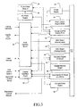
- FIG. 3 is a schematic of the laser's internal control system for a preferred embodiment of the present invention.
- FIG. 4 is a timing schematic depicting the GATE, Serial Input and Trigger Timing sequences in accordance with the external control system of the present invention.
- FIG. 5 is a schematic flowchart of the control process used by the present invention to provide external energy control.
- FIG. 6 is a continuation of the control schematic of FIG. 5.
- FIG. 7 is a schematic flowchart of the GATE and Trigger Timing interrupt program of the present invention.
- FIG. 8 is a schematic flowchart of the High Speed Serial Input and Delay interrupt program of the present invention.
- the present invention provides an apparatus and method for allowing external control of the supplied voltage used for creating a laser discharge. By utilizing sensors on or near the wafer itself, more accurate information regarding the laser output is obtained, which can be used by the external control to monitor and more precisely correct the energy output of the laser.
- the laser-stepper system previously described in FIG. 1 is shown having the additional external control 110 in accordance with the present invention, operably coupled to the output control unit 6.
- the gas discharge laser control system of the present invention is shown as being constructed around a popular bus structure; specifically in the preferred embodiment, the STD bus, in the form of a card cage accepting STD bus compatible commercially available card level components for the system.
- power for the system is provided by power supply 20, which provides power to the power lines of the bus structure for powering the other boards in the system.
- a gas discharge laser control system utilized by the present invention will include a main control board 22, containing a processor and associated support circuitry, which will function as the master processor in the system.
- the main control board 22 is a single board computer having, at a minimum, an Intel type 486 processor with a minimum of 25 MHz clock speed, 128 Kbytes of battery backed-up RAM (random access memory), at least 512 Kbytes of flash memory and at least 512 Kbytes DRAM.
- This STD-80/MPX compatible processor board will have the capability of becoming a bus master in a multi-processor environment.
- a trigger control board 24 which operating on its own program, will control a separate high voltage power supply 26 and the pulse power module 28 to provide the pulse control and trigger for each pulse of the laser.
- the trigger control board (TCB) is also a single board computer having, at a minimum, an Intel type 486 processor with a minimum of 25 MHz clock speed, at least 128 Kbytes of battery-backed RAM, at least 512 Kbytes of flash memory and at least 512 Kbytes DRAM.
- This STD-80/MPX compatible processor board will also have the capability of becoming a bus master in a multi-processor environment.
- An SBX high speed serial/parallel I/O board is also provided as a daughter board which resides on the TCB for pulse-to-pulse interface capability.
- the memory on the main control board 22 is dedicated for use by the processor on that board.
- the processor is at least a 486 processor.
- the memory on the trigger control board 24 is dedicated for use by at least a 486 processor on that board.
- an additional memory board 30 is provided on the STD bus for shared use by the processors on the main control board 22 and the trigger control board 24.
- the shared memory 30 in the preferred embodiment is a memory card containing at least 64 Kbytes of RAM in the STD bus card cage. It has an address space separate and apart from the address space of the memory on the main control board 22 and the memory on the trigger control board 24, but still within the total address space of the processors on these boards.
- the laser control system used in the present invention also includes an analog-to-digital converter board 32 for receiving analog inputs, and a digital-to-analog converter board 34 for outputting analog signals.
- the analog input board 32 in the preferred embodiment contains thirty-two 12-bit analog input channels, multiplexed into a single 12-bit analog-to-digital (A/D) converter. Those skilled in the art will recognize that thirty-two channels was a design choice, and that the number of channels for a particular application may vary based upon operational requirements.
- the output of the analog-to-digital converter board 32 is accessible by the processors on the main control board 22 and the trigger control board 24 as an I/O mapped card.
- the digital-to-analog converter board 34 in the preferred embodiment contains eight separate 12-bit digital-to-analog output channels, it too being accessible by both processors as an I/O mapped card on the STD bus. As previously stated, eight channels was a design choice which those skilled in the art will recognize may vary depending upon operational requirements. There is also provided a second thirty-two channel A/D converter board, specifically dedicated to trigger control board 24.
- a discreet digital I/O board 36 Also included in the STD bus card cage is a discreet digital I/O board 36 and a quad serial I/O board 38.
- the discreet digital I/O board in the preferred embodiment provides a plurality of decoded (dedicated) I/O lines suitable for various functions.
- the discreet digital I/O board 36 provides control of such things as the shutter, a dedicated line having only two states, open and closed.
- a control interface panel 40 is provided for communicating with and receiving instructions from a host control system, or alternatively, receiving instructions from a hand-held control device.
- the host control system and/or hand-held control device provides a customer-defined interface generally including certain dedicated or decoded lines for control signals such as a trigger signal when the same is provided externally to the laser control system of the present invention.
- control signals such as a trigger signal when the same is provided externally to the laser control system of the present invention.
- Such signals other than a trigger command itself, are provided to the discreet digital I/O board 36 through the control interface panel 40 as decoded digital signals.
- the trigger command may come from the host control system, or the hand-held control device, with the trigger command being provided through the control interface panel 40 to directly trigger the trigger control board 24 without intervention of the processor on the main control board 22 or use of the STD bus, all of course in accordance with software then operating in the trigger control board 24 in accordance with this mode.
- the quad serial I/O board 38 in the preferred embodiment contains four UART's (universal asynchronous receiver/transmitters) to provide RS-232 communication capabilities to and from the laser control system in addition to the two RS-232 communication ports located on the processor. This type of communication with a system is useful not only for initialization purposes, but also for providing information to the host system regarding laser status and operation as the system is operating.
- a programmable counter/timer board 42 providing programmable timers for the main control board 22 and the trigger control board 24, as well as counters to count events of other devices in the system such as the fan inside the chamber.
- the laser functions are monitored and/or controlled either directly from the main control board 22 or the trigger control board 24 through a wire harness board 44 coupled to the various monitoring and control devices, or by one of these boards through the STD bus and through the analog-to-digital converter board 32, the digital-to-analog converter board 34 counter and timer boards, and/or the discreet digital I/O board 36.
- the analog-to-digital converter board provides the ability to interpret analog monitoring signals from the laser system, with the digital-to-analog converter board 34 providing the ability to output analog control signals for controlling analog proportional control devices in the laser system.
- each processor board includes its own dedicated I/O resources is to keep contention for the shared I/O resources on the STD bus to a minimum.
- the processors use a bus arbitration scheme as defined by the STD 80-MPX standard.
- the master gains control of the bus.
- control is passed to the first slave processor. While the embodiment described herein only includes a single slave processor, this embodiment will accommodate up to seven processors. Accordingly, if more than one slave processor is used, the initialization process will continue until all slave processors have been initialized. When the last slave processor has been initialized, then the first slave processor establishes communications with the master and requests its program to be loaded.
- the master then transfers program data to a specific location in shared memory in discrete chunks, such as 2 Kbytes, signaling the slave that data is available upon completion of the transfer of each discrete chunk.
- the master then waits for the slave to load the program data and signal back for more. This process repeats until the entire program is loaded.
- the processors then begin operating independently, with each processor constantly checking shared memory for information from each other.
- an interrupt scheme which will be described later, may be implemented for data passing between processors, providing a more efficient transfer mechanism and relieving the back plane of the STD card cage of a lot of otherwise unnecessary signal traffic.
- the advantage realized is that the processors in the gas discharge laser control system are configured to serve distinct and different purposes.
- the master processor has a real-time operating system which, in one embodiment, has approximately 32 tasks under its control. These tasks are database managers, I/O monitoring routines, post-serial and parallel interface managers, user interface tasks, inter-processor data passing tasks, laser gas management and monitoring chamber temperature control, interlock monitoring and reporting, laser state managing, and others. These tasks are generally characterized as the slow, less time-critical tasks within the laser control system.
- the trigger control processor the only slave processor in the specific embodiment described, has the very time-critical tasks, such as the high voltage profiling, laser repetition rate, high speed user interface, and any laser pulse-to-laser pulse processing that needs to be done. As previously discussed, however, up to seven processors may be dedicated to the handling of very time-critical tasks. As a matter of comparison, in the embodiment described herein, the host processor operates on a 5 millisecond time base, with event timing accuracies of approximately ⁇ 10 milliseconds, whereas the slave processor operates on a 100 microsecond time base, with timing accuracies in the ⁇ 10 nanosecond range.
- the processor on the trigger control board does not have a real-time operating system, but in a preferred embodiment has a program written in a high level programming language, such as C, and takes complete control of all onboard resources as needed.
- the master processor uses its real-time operating system to manage system resources so that it can concentrate on handling the complex task of managing the laser system and coordinating the many tasks needed to do this successfully.
- Specific master tasks may include:
- sensors placed on or near the wafer provide measurement information regarding laser energy actually received by the wafer to the external control 110 of FIG. 2. Based upon this received measurement information, the external control will make any necessary corrections to the laser's energy output, pulse repetition or pulse duration, to ensure accurate energy dose control to the wafer.
- Control inputs from the external control are provided via a high speed communication interface, such as an RS 485/422, directly to the SBX high speed serial/parallel I/O board which resides on TCB 24 of FIG. 3.
- a high speed communication interface such as an RS 485/422
- SBX high speed serial/parallel I/O board which resides on TCB 24 of FIG. 3.
- HV Set High Voltage Set Point
- HV min This minimum is a Configurable in the laser's operating system, and represents a lower limit of a factory established High Voltage range.
- the external control is sending serial data 110, in a 2-byte or other sequence, to establish a Command HV Set point, HV Cmd, for charge unit 17 of FIG. 2.
- a delay period 120 as per argument 10 (ARG 10) in Table 1, is established wherein if the serial data is not input within a predetermined period, such as 5 ⁇ s, the HV Cmd will be set to a default set point.
- the inputs are likewise required to be received by the laser's output control unit within an established GATE to TRIGGER delay period 130, as per ARG 4, such as 300 ⁇ s, as shown in FIG. 4.
- the value input for HV Cmd is checked by the TCB to ensure it falls within limits set as a Configurable for laser operation.
- An example of the HV range is shown by the serial data HV ramp of FIG. 4., wherein stepped intervals for a start and end point is defined by ARG 6 to ARG 8 of Table 1.
- HVavg a running average set point value is used, "HVavg.”
- HVavg is initialized to an established first default set pont value, HVd, during the system control setup sequence.
- the HVavg value is calculated by averaging the last N number of HV Cmd values used to fire the laser. The number N is a Configurable set by the user and is based upon the operating parameters of the laser.
- Stepper control unit 10 may then send a trigger pulse 140 after the appropriate delay time 130, as per ARG 4, shown in FIG. 4, to fire the laser. Firing of the laser will continue in accordance with the defined repetition rate 170 until the defined burst count expires or the GATE is dropped as per ARG 1. If the GATE drops during a burst, the remainder of the pulses in the burst count is terminated.
- the second HV setting, HV Cmd2 After the first trigger signal (within the GATE pulse), the second HV setting, HV Cmd2, must finish its input prior to the expiration of the Trigger to Serial Data delay period 150, as per ARG 5, as shown in FIG. 4.
- These delay periods and input limitations will be driven by the particular hardware used. For example, with a system capable of running at 375 K baud, the transmit time for 2 bytes is 48 ⁇ s. As speeds for UART's increase, these time periods will decrease.
- FIG. 5 and FIG. 6 An example of the signal inputs from the external control unit used to establish the HV set point of the laser is provided in FIG. 5 and FIG. 6.
- the following paragraphs are numbered to correspond to numbered steps in FIG. 5 and FIG. 6.
- the paragraph numbered "3" below refers to the step numbered as "3" in the Figures.
- the numbers in the referenced Figures are to the left of the designated steps in the flowchart
- Step 12 If in Step 12 it is determined that a GATE OFF condition exists the program moves from Step 12 to Step 14a.
- Steps 1 to 8 of FIG. 5 are initially performed.
- Step 8 enables the interrupt programs TC0 ⁇ and TC2 of FIG. 7 and FIG. 8, respectively, and initially transmits a GATE ON signal 100 to the laser as shown in FIG. 4.
- the initial HVmin setting for the HV Cmd in Step 3 is checked in Steps 9 and 10 to determine if a new HV Cmd setting has been input
- Step 11 checks to determine if a TC2 (Trigger/Gate) interrupt has occurred.
- TC2 will be governed by the external controller's counter/timer, which will determine the signaling for TC2 operation.
- Step 21 verifies whether the GATE ON signal is dose to terminating based on the time and the GATE signal duration. If time remains in the GATE period, Step 26 verifies that the stepper's trigger control is active and fires the laser upon receiving a trigger command from the stepper, as shown by element 140 of FIG. 4.
- Step 26 of TC2 triggers TC0 ⁇ to again wait the specified delay 150 and send serial inputs 110 of Fig. 4. Any changes to these HV Cmd inputs will be provided in Steps 9 and 10 as previously described.
- TC2 returns to the main loop and runs Steps 9 to 11 again In Step 11, the previous firing of the laser will cause the main program to run Steps 12 to 14, wherein the time remaining for the GATE ON or GATE OFF period is checked and reset to allow for the required number of trigger pulses to be fired.
- External sensors monitor energy dose to the wafers and modify the HV Cmd setting as discussed to allow a more precise control of energy output
Landscapes
- Physics & Mathematics (AREA)
- Electromagnetism (AREA)
- Engineering & Computer Science (AREA)
- Plasma & Fusion (AREA)
- Optics & Photonics (AREA)
- Lasers (AREA)
- Laser Beam Processing (AREA)
- Exposure Of Semiconductors, Excluding Electron Or Ion Beam Exposure (AREA)
Applications Claiming Priority (2)
| Application Number | Priority Date | Filing Date | Title |
|---|---|---|---|
| US601907 | 1996-02-15 | ||
| US08/601,907 US5657334A (en) | 1996-02-15 | 1996-02-15 | External high voltage control for a laser system |
Publications (3)
| Publication Number | Publication Date |
|---|---|
| EP0790681A2 true EP0790681A2 (de) | 1997-08-20 |
| EP0790681A3 EP0790681A3 (de) | 1998-05-20 |
| EP0790681B1 EP0790681B1 (de) | 2000-07-12 |
Family
ID=24409233
Family Applications (1)
| Application Number | Title | Priority Date | Filing Date |
|---|---|---|---|
| EP97300340A Expired - Lifetime EP0790681B1 (de) | 1996-02-15 | 1997-01-20 | Externe Hochspannungsansteuerung für ein Lasersystem |
Country Status (6)
| Country | Link |
|---|---|
| US (1) | US5657334A (de) |
| EP (1) | EP0790681B1 (de) |
| JP (1) | JP3523767B2 (de) |
| KR (1) | KR100246489B1 (de) |
| CA (1) | CA2196131C (de) |
| DE (1) | DE69702462T2 (de) |
Cited By (9)
| Publication number | Priority date | Publication date | Assignee | Title |
|---|---|---|---|---|
| DE19820575A1 (de) * | 1998-05-08 | 1999-12-23 | Leica Microsystems | Verfahren zum Betrieb einer Laserlichtquelle |
| WO2001001532A1 (en) * | 1999-06-23 | 2001-01-04 | Lambda Physik Ag | Device for on-line control of output power of vacuum-uv laser |
| WO2001055684A3 (en) * | 2000-01-25 | 2002-01-10 | Lambda Physik Ag | Energy monitor for molecular fluorine laser |
| US6487229B2 (en) | 1999-02-12 | 2002-11-26 | Lambda Physik Ag | Beam delivery system for molecular fluorine (F2) laser |
| US6529533B1 (en) | 1999-11-22 | 2003-03-04 | Lambda Physik Ag | Beam parameter monitoring unit for a molecular fluorine (F2) laser |
| US6795456B2 (en) | 1999-12-20 | 2004-09-21 | Lambda Physik Ag | 157 nm laser system and method for multi-layer semiconductor failure analysis |
| US6998620B2 (en) | 2001-08-13 | 2006-02-14 | Lambda Physik Ag | Stable energy detector for extreme ultraviolet radiation detection |
| US7075963B2 (en) | 2000-01-27 | 2006-07-11 | Lambda Physik Ag | Tunable laser with stabilized grating |
| CN101394060B (zh) * | 2007-09-21 | 2010-12-01 | 中国科学院大连化学物理研究所 | 燃烧驱动全气相碘激光燃烧室的点火控制装置及控制方法 |
Families Citing this family (27)
| Publication number | Priority date | Publication date | Assignee | Title |
|---|---|---|---|---|
| US5764505A (en) * | 1996-01-23 | 1998-06-09 | Cymer, Inc. | Gas discharge laser control systems using multiple CPU's with shared memory on a common bus |
| DE19603637C1 (de) | 1996-02-01 | 1997-07-31 | Lambda Physik Gmbh | Laser zur Erzeugung schmalbandiger Strahlung |
| US6141081A (en) * | 1997-08-08 | 2000-10-31 | Cymer, Inc. | Stepper or scanner having two energy monitors for a laser |
| US5946337A (en) * | 1998-04-29 | 1999-08-31 | Lambda Physik Gmbh | Hybrid laser resonator with special line narrowing |
| US6476987B1 (en) | 1999-08-04 | 2002-11-05 | Lambda Physik Ag | Excimer laser with line narrowing |
| US6285701B1 (en) | 1998-08-06 | 2001-09-04 | Lambda Physik Ag | Laser resonator for improving narrow band emission of an excimer laser |
| US6424666B1 (en) | 1999-06-23 | 2002-07-23 | Lambda Physik Ag | Line-narrowing module for high power laser |
| US6144686A (en) * | 1998-08-28 | 2000-11-07 | Cymer, Inc. | Tangential fan with cutoff assembly and vibration control for electric discharge laser |
| US6700915B2 (en) | 1999-03-12 | 2004-03-02 | Lambda Physik Ag | Narrow band excimer laser with a resonator containing an optical element for making wavefront corrections |
| US6298080B1 (en) | 1999-03-12 | 2001-10-02 | Lambda Physik Ag | Narrow band excimer or molecular fluorine laser with adjustable bandwidth |
| US6111907A (en) * | 1999-03-17 | 2000-08-29 | Cymer, Inc. | Laser chamber installation in and removal from a laser system housing |
| JP2001044113A (ja) | 1999-08-02 | 2001-02-16 | Nikon Corp | ビーム出力制御方法、ビーム出力装置、及び露光システム、並びに当該露光システムを用いるデバイス製造方法 |
| JP2001148344A (ja) | 1999-09-09 | 2001-05-29 | Nikon Corp | 露光装置、エネルギ源の出力制御方法、該方法を用いるレーザ装置、及びデバイス製造方法 |
| JP4139015B2 (ja) * | 1999-09-21 | 2008-08-27 | 株式会社小松製作所 | パルスレーザ制御システム |
| US6618425B1 (en) * | 1999-11-17 | 2003-09-09 | Cymer, Inc. | Virtual laser operator |
| US6618403B2 (en) | 2000-03-16 | 2003-09-09 | Lambda Physik Ag | Method and apparatus for compensation of beam property drifts detected by measurement systems outside of an excimer laser |
| US6697695B1 (en) * | 2000-04-25 | 2004-02-24 | Komatsu Ltd. | Laser device management system |
| US6603789B1 (en) | 2000-07-05 | 2003-08-05 | Lambda Physik Ag | Narrow band excimer or molecular fluorine laser with improved beam parameters |
| US6801561B2 (en) | 2000-09-25 | 2004-10-05 | Lambda Physik Ag | Laser system and method for spectral narrowing through wavefront correction |
| US7164703B2 (en) * | 2003-02-20 | 2007-01-16 | Lambda Physik Ag | Temperature control systems for excimer lasers |
| US7848378B2 (en) * | 2005-08-05 | 2010-12-07 | Photomedex, Inc. | Apparatus and method for monitoring power of a UV laser |
| US20070030876A1 (en) * | 2005-08-05 | 2007-02-08 | Levatter Jeffrey I | Apparatus and method for purging and recharging excimer laser gases |
| JP4845969B2 (ja) | 2005-12-02 | 2011-12-28 | エンテグリース,インコーポレイテッド | ポンプ制御装置を結合する入出力システム、方法、および装置 |
| TW200903935A (en) * | 2007-03-27 | 2009-01-16 | Photomedex | Method and apparatus for efficiently operating a gas discharge excimer laser |
| WO2014017562A1 (ja) * | 2012-07-26 | 2014-01-30 | ギガフォトン株式会社 | レーザ装置及びレーザ装置の制御方法 |
| TWI523357B (zh) * | 2013-03-19 | 2016-02-21 | Sumitomo Heavy Industries | Laser processing device and laser processing method |
| JP7411082B2 (ja) * | 2019-12-18 | 2024-01-10 | サイマー リミテッド ライアビリティ カンパニー | 光源装置用のエネルギー補正モジュール |
Family Cites Families (13)
| Publication number | Priority date | Publication date | Assignee | Title |
|---|---|---|---|---|
| JP2651147B2 (ja) * | 1987-03-20 | 1997-09-10 | ファナック 株式会社 | レーザー発振器制御回路 |
| DE3714503C2 (de) * | 1987-04-30 | 1995-07-27 | Lambda Physik Forschung | Steuerschaltung für einen gepulsten Gas-Laser und Verfahren zum Initialisieren der Steuerschaltung |
| JPS6457774A (en) * | 1987-08-28 | 1989-03-06 | Komatsu Mfg Co Ltd | Controlling method for output of excimer laser |
| JPH0714099B2 (ja) * | 1988-11-24 | 1995-02-15 | 株式会社島津製作所 | エキシマレーザ装置 |
| JPH0337523U (de) * | 1989-08-23 | 1991-04-11 | ||
| JP3316850B2 (ja) * | 1990-04-25 | 2002-08-19 | 株式会社ニコン | エネルギー量制御装置 |
| JP2785157B2 (ja) * | 1990-10-05 | 1998-08-13 | キヤノン株式会社 | 光量制御装置および露光装置 |
| JP3378271B2 (ja) * | 1992-06-11 | 2003-02-17 | 株式会社ニコン | 露光方法及び装置、並びに前記方法を使用するデバイス製造方法 |
| US5463650A (en) * | 1992-07-17 | 1995-10-31 | Kabushiki Kaisha Komatsu Seisakusho | Apparatus for controlling output of an excimer laser device |
| JP3425447B2 (ja) * | 1992-09-14 | 2003-07-14 | 株式会社小松製作所 | エキシマレーザ装置の出力制御装置 |
| JPH06164041A (ja) * | 1992-11-18 | 1994-06-10 | Komatsu Ltd | ガスレーザ装置 |
| JP2631080B2 (ja) * | 1993-10-05 | 1997-07-16 | 株式会社小松製作所 | レーザ装置の出力制御装置 |
| JPH07142801A (ja) * | 1993-11-12 | 1995-06-02 | Matsushita Electric Ind Co Ltd | レーザ装置 |
-
1996
- 1996-02-15 US US08/601,907 patent/US5657334A/en not_active Expired - Lifetime
-
1997
- 1997-01-20 DE DE69702462T patent/DE69702462T2/de not_active Expired - Lifetime
- 1997-01-20 EP EP97300340A patent/EP0790681B1/de not_active Expired - Lifetime
- 1997-01-28 CA CA002196131A patent/CA2196131C/en not_active Expired - Fee Related
- 1997-02-14 KR KR1019970004413A patent/KR100246489B1/ko not_active Expired - Lifetime
- 1997-02-17 JP JP04848297A patent/JP3523767B2/ja not_active Expired - Fee Related
Non-Patent Citations (1)
| Title |
|---|
| None |
Cited By (15)
| Publication number | Priority date | Publication date | Assignee | Title |
|---|---|---|---|---|
| DE19820575A1 (de) * | 1998-05-08 | 1999-12-23 | Leica Microsystems | Verfahren zum Betrieb einer Laserlichtquelle |
| DE19820575B4 (de) * | 1998-05-08 | 2012-03-29 | Leica Microsystems Cms Gmbh | Verfahren zum Betrieb einer pulsierenden Laserlichtquelle |
| US6487229B2 (en) | 1999-02-12 | 2002-11-26 | Lambda Physik Ag | Beam delivery system for molecular fluorine (F2) laser |
| US6442182B1 (en) | 1999-02-12 | 2002-08-27 | Lambda Physik Ag | Device for on-line control of output power of vacuum-UV laser |
| US6463084B1 (en) | 1999-02-12 | 2002-10-08 | Lambda Physik Ag | Device for on-line control of output power of vacuum-UV laser |
| US6477192B2 (en) | 1999-02-12 | 2002-11-05 | Lambda Physik Ag | Device for on-line control of output power of vacuum-UV laser |
| US6490305B2 (en) | 1999-02-12 | 2002-12-03 | Lambda Physik Ag | Beam delivery system for molecular fluorine (F2) laser |
| WO2001001532A1 (en) * | 1999-06-23 | 2001-01-04 | Lambda Physik Ag | Device for on-line control of output power of vacuum-uv laser |
| US6529533B1 (en) | 1999-11-22 | 2003-03-04 | Lambda Physik Ag | Beam parameter monitoring unit for a molecular fluorine (F2) laser |
| US6795456B2 (en) | 1999-12-20 | 2004-09-21 | Lambda Physik Ag | 157 nm laser system and method for multi-layer semiconductor failure analysis |
| WO2001055684A3 (en) * | 2000-01-25 | 2002-01-10 | Lambda Physik Ag | Energy monitor for molecular fluorine laser |
| US6907058B2 (en) | 2000-01-25 | 2005-06-14 | Lambda Physik Ag | Energy monitor for molecular fluorine laser |
| US7075963B2 (en) | 2000-01-27 | 2006-07-11 | Lambda Physik Ag | Tunable laser with stabilized grating |
| US6998620B2 (en) | 2001-08-13 | 2006-02-14 | Lambda Physik Ag | Stable energy detector for extreme ultraviolet radiation detection |
| CN101394060B (zh) * | 2007-09-21 | 2010-12-01 | 中国科学院大连化学物理研究所 | 燃烧驱动全气相碘激光燃烧室的点火控制装置及控制方法 |
Also Published As
| Publication number | Publication date |
|---|---|
| JP3523767B2 (ja) | 2004-04-26 |
| CA2196131C (en) | 2004-04-06 |
| EP0790681A3 (de) | 1998-05-20 |
| EP0790681B1 (de) | 2000-07-12 |
| CA2196131A1 (en) | 1997-08-16 |
| KR970063843A (ko) | 1997-09-12 |
| DE69702462D1 (de) | 2000-08-17 |
| US5657334A (en) | 1997-08-12 |
| JPH09232659A (ja) | 1997-09-05 |
| KR100246489B1 (ko) | 2000-03-15 |
| DE69702462T2 (de) | 2000-11-23 |
Similar Documents
| Publication | Publication Date | Title |
|---|---|---|
| EP0790681B1 (de) | Externe Hochspannungsansteuerung für ein Lasersystem | |
| EP0786841B1 (de) | Regelungssystem für Gasentladungslaser unter Verwendung mehrerer zentraler Prozessoreinheiten mit gemeinsam geteiltem Speicher und gemeinsamen Bus | |
| TWI421643B (zh) | A light source device and an exposure device using the same | |
| US5463650A (en) | Apparatus for controlling output of an excimer laser device | |
| JP2724993B2 (ja) | レーザ加工装置およびレーザ装置 | |
| EP0329140B1 (de) | Belichtungskontrollsystem für Vollfeld-Photolithographie mit gepulsten Quellen | |
| US9130337B1 (en) | System and method for automatic gas optimization in a two-chamber gas discharge laser system | |
| US6219367B1 (en) | Method for determining life of laser light source | |
| US8295316B2 (en) | Method and system for managing light source operation | |
| CN113853551B (zh) | 用于多个深紫外光学振荡器的控制系统 | |
| TWI432911B (zh) | A light source device and an exposure device using the same | |
| KR100250394B1 (ko) | 엑시머 레이저의 가스 재공급 방법 및 장치 | |
| JP2663864B2 (ja) | エキシマレーザ | |
| US20250385480A1 (en) | Apparatus for and method of conditioning light source after idle period | |
| JP7529805B2 (ja) | 光源の制御装置 | |
| JPH0738179A (ja) | ガス圧力制御装置 | |
| JPH10173262A (ja) | エキシマレーザ装置のガス供給制御装置およびガス供給制御方法 | |
| JPH0427182A (ja) | パルスレーザ装置 | |
| JPH11277260A (ja) | レーザ装置、該レーザ装置を用いる露光システム、およびレーザ制御方法 | |
| JPH083771B2 (ja) | 発振制御装置 |
Legal Events
| Date | Code | Title | Description |
|---|---|---|---|
| PUAI | Public reference made under article 153(3) epc to a published international application that has entered the european phase |
Free format text: ORIGINAL CODE: 0009012 |
|
| AK | Designated contracting states |
Kind code of ref document: A2 Designated state(s): DE NL |
|
| PUAL | Search report despatched |
Free format text: ORIGINAL CODE: 0009013 |
|
| AK | Designated contracting states |
Kind code of ref document: A3 Designated state(s): DE NL |
|
| 17P | Request for examination filed |
Effective date: 19981009 |
|
| 17Q | First examination report despatched |
Effective date: 19981117 |
|
| GRAG | Despatch of communication of intention to grant |
Free format text: ORIGINAL CODE: EPIDOS AGRA |
|
| RIC1 | Information provided on ipc code assigned before grant |
Free format text: 6H 01S 3/097 A, 6H 01S 3/134 B, 6H 01S 3/225 B |
|
| GRAG | Despatch of communication of intention to grant |
Free format text: ORIGINAL CODE: EPIDOS AGRA |
|
| GRAH | Despatch of communication of intention to grant a patent |
Free format text: ORIGINAL CODE: EPIDOS IGRA |
|
| GRAH | Despatch of communication of intention to grant a patent |
Free format text: ORIGINAL CODE: EPIDOS IGRA |
|
| GRAA | (expected) grant |
Free format text: ORIGINAL CODE: 0009210 |
|
| AK | Designated contracting states |
Kind code of ref document: B1 Designated state(s): DE NL |
|
| REF | Corresponds to: |
Ref document number: 69702462 Country of ref document: DE Date of ref document: 20000817 |
|
| EN | Fr: translation not filed | ||
| PLBE | No opposition filed within time limit |
Free format text: ORIGINAL CODE: 0009261 |
|
| STAA | Information on the status of an ep patent application or granted ep patent |
Free format text: STATUS: NO OPPOSITION FILED WITHIN TIME LIMIT |
|
| 26N | No opposition filed | ||
| PGFP | Annual fee paid to national office [announced via postgrant information from national office to epo] |
Ref country code: NL Payment date: 20150129 Year of fee payment: 19 |
|
| PGFP | Annual fee paid to national office [announced via postgrant information from national office to epo] |
Ref country code: DE Payment date: 20150121 Year of fee payment: 19 |
|
| REG | Reference to a national code |
Ref country code: DE Ref legal event code: R082 Ref document number: 69702462 Country of ref document: DE Representative=s name: GRUENECKER PATENT- UND RECHTSANWAELTE PARTG MB, DE Ref country code: DE Ref legal event code: R081 Ref document number: 69702462 Country of ref document: DE Owner name: CYMER, LLC (N.D.GES. D.STAATES NEVADA), SAN DI, US Free format text: FORMER OWNER: CYMER, INC., SAN DIEGO, CALIF., US |
|
| REG | Reference to a national code |
Ref country code: DE Ref legal event code: R119 Ref document number: 69702462 Country of ref document: DE |
|
| REG | Reference to a national code |
Ref country code: NL Ref legal event code: MM Effective date: 20160201 |
|
| PG25 | Lapsed in a contracting state [announced via postgrant information from national office to epo] |
Ref country code: DE Free format text: LAPSE BECAUSE OF NON-PAYMENT OF DUE FEES Effective date: 20160802 |
|
| PG25 | Lapsed in a contracting state [announced via postgrant information from national office to epo] |
Ref country code: NL Free format text: LAPSE BECAUSE OF NON-PAYMENT OF DUE FEES Effective date: 20160201 |