EP0790439B1 - Drehmomentwandler mit Überbrückungskupplung in Konusbauform - Google Patents
Drehmomentwandler mit Überbrückungskupplung in Konusbauform Download PDFInfo
- Publication number
- EP0790439B1 EP0790439B1 EP97101661A EP97101661A EP0790439B1 EP 0790439 B1 EP0790439 B1 EP 0790439B1 EP 97101661 A EP97101661 A EP 97101661A EP 97101661 A EP97101661 A EP 97101661A EP 0790439 B1 EP0790439 B1 EP 0790439B1
- Authority
- EP
- European Patent Office
- Prior art keywords
- clutch
- torque converter
- conical
- lock
- cone
- Prior art date
- Legal status (The legal status is an assumption and is not a legal conclusion. Google has not performed a legal analysis and makes no representation as to the accuracy of the status listed.)
- Expired - Lifetime
Links
- 238000013016 damping Methods 0.000 description 4
- 230000005540 biological transmission Effects 0.000 description 3
- 238000002485 combustion reaction Methods 0.000 description 2
- 230000002787 reinforcement Effects 0.000 description 2
- 230000008878 coupling Effects 0.000 description 1
- 238000010168 coupling process Methods 0.000 description 1
- 238000005859 coupling reaction Methods 0.000 description 1
- 230000000694 effects Effects 0.000 description 1
- 230000001970 hydrokinetic effect Effects 0.000 description 1
- 239000000314 lubricant Substances 0.000 description 1
- 238000004519 manufacturing process Methods 0.000 description 1
Images
Classifications
-
- F—MECHANICAL ENGINEERING; LIGHTING; HEATING; WEAPONS; BLASTING
- F16—ENGINEERING ELEMENTS AND UNITS; GENERAL MEASURES FOR PRODUCING AND MAINTAINING EFFECTIVE FUNCTIONING OF MACHINES OR INSTALLATIONS; THERMAL INSULATION IN GENERAL
- F16H—GEARING
- F16H45/00—Combinations of fluid gearings for conveying rotary motion with couplings or clutches
- F16H45/02—Combinations of fluid gearings for conveying rotary motion with couplings or clutches with mechanical clutches for bridging a fluid gearing of the hydrokinetic type
-
- F—MECHANICAL ENGINEERING; LIGHTING; HEATING; WEAPONS; BLASTING
- F16—ENGINEERING ELEMENTS AND UNITS; GENERAL MEASURES FOR PRODUCING AND MAINTAINING EFFECTIVE FUNCTIONING OF MACHINES OR INSTALLATIONS; THERMAL INSULATION IN GENERAL
- F16H—GEARING
- F16H45/00—Combinations of fluid gearings for conveying rotary motion with couplings or clutches
- F16H45/02—Combinations of fluid gearings for conveying rotary motion with couplings or clutches with mechanical clutches for bridging a fluid gearing of the hydrokinetic type
- F16H2045/0273—Combinations of fluid gearings for conveying rotary motion with couplings or clutches with mechanical clutches for bridging a fluid gearing of the hydrokinetic type characterised by the type of the friction surface of the lock-up clutch
- F16H2045/0294—Single disk type lock-up clutch, i.e. using a single disc engaged between friction members
Definitions
- the invention relates to a torque converter Bridging clutch in cone design, which in the preamble of Claim 1 explained Art.
- the present invention is based on such known lock-up clutches in cone design and has the goal set to demonstrate measures by means of which an adjustment that can be achieved with lock-up clutches in the form of a cone Self-reinforcement to that intended for each purpose Torque capacity of a torque converter with simple means is possible.
- the inner wall of the torque converter housing at least two concentric conical surfaces has, the radially inner conical surface a smaller Gain angle and its radially outer conical surface has a larger gain angle and this with Clutch plates with different radial expansion and differently conically angled friction disc areas can work together while maintaining a unified Torque converter housing a series of for different Torque transmission capacities designed Torque converters with lock-up clutches in cone design be created.
- the clutch discs provided for the series can here in their hub and damper area be formed and only in their radially outer, conical Differentiate between friction disc areas.
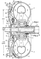
- a torque converter housing 1 which is known per se Way from a drive shell 2 or a jacket component 2 and an associated impeller housing 3, are in a circular flow cycle one with a multitude impeller P provided with blades, a stator or Stator wheel S and a turbine wheel T arranged.
- the stator or stator S is in a conventional manner via a freewheel arrangement 4 on a fixed hollow shaft 5 supported.
- the turbine wheel T is driven via a turbine hub 6 connected to a turbine shaft 7, which has an input member, e.g. for one made up of several planetary gear sets forms automatic transmission of a motor vehicle.
- the torque converter housing 1 is with its jacket component 2, e.g. via a centering sleeve 8 on a flywheel arrangement an internal combustion engine (not shown) centered and of this over a, a certain axial and radial Flexibility ensuring drive pulley 9 via bolts 10 driving connected.
- the other side of the torque converter housing 1 by the Impeller part 3 is formed, based here in a known manner Way via a hollow drive shaft 11 in a bearing section (not shown) of the gear housing, the Hollow drive shaft 11 at the same time the drive connection a lubricant pump required for an automatic transmission manufactures.
- Such a lock-up clutch arrangement 12 or 12 ' exists essentially from a damping arrangement 13 and a clutch disc 14 or 14 '.
- the damping arrangement 13 essentially consists of a base plate 15, the rotationally fixed via a spline toothing 16 is connected to the turbine hub 6.
- the base plate 15 has a plurality of window openings 17 in which tangentially arranged coil springs 18 arranged in this way are that they alternate with the base plate 15 and with the The clutch disc 14 or 14 'cooperate.
- the springs 18 are secured against falling out by a cover plate 19, the bolt 20 rotatably with the clutch disc 14 or 14 'is connected.
- the inner area of the clutch discs 14 or 14 ' consists of a sleeve extension 22 or 22 ', which is relatively rotatably arranged on the clutch hub is.
- the radial outer area of the clutch disks 14 and 14 ' is in the angled friction disc areas 23 and 23 ' a support of corresponding friction linings 24 or 24 '.
- the drive shell or the Sheath component 2 with at least two concentric to each other Provide conical surfaces K1 and K2, their radially inner Cone surface K1 has a smaller reinforcement angle and whose radially outer conical surface has a larger reinforcement angle has, whereby this with clutch discs with different radial extension and different conical angle can interact.
Landscapes
- Engineering & Computer Science (AREA)
- General Engineering & Computer Science (AREA)
- Mechanical Engineering (AREA)
- Mechanical Operated Clutches (AREA)
Description
- Fig. 1
- die obere Hälfte eines erfindungsgemäßen Drehmomentwandlers mit einer Überbrückungskupplung in Konusbauform und
- Fig. 2
- die untere Hälfte eines erfindungsgemäßen Drehmomentwandlers mit einer Überbrückungskupplung in Konusbauform, wobei hier eine radial vergrößerte Kupplungsscheibe mit einer höheren Drehmomentkapazität vorgesehen ist.
Claims (3)
- Drehmomentwandler mit Überbrückungskupplung (12 ; 12') in Konusbauform, mit einer unmittelbar mit einer konischen Innenwandung der Antriebsschale (2) des Drehmomentwandlergehäuses (1) zusammenwirkenden Kupplungsscheibe mit konischem Reibscheibenbereich,
dadurch gekennzeichnet, daßdie Innenwandung der Antriebsschale (2) des Drehmomentwandlergehäuses (1) zumindest zwei konzentrisch zueinander liegende Konusflächen (K1 und K2) aufweist, deren radial innere Konusfläche (K1) mit einem geringeren Verstärkungswinkel und deren radial äußere Konusfläche (K2) mit einem größeren Verstärkungswinkelmit Kupplungsscheiben (14 bzw. 14') mit unterschiedlich radialer Erstreckung und unterschiedlich konisch abgewinkelten Reibscheibenbereichen (23 bzw. 23') modular nach Art eines Bausatzes zusammenwirkt. - Drehmomentwandler mit Überbrückungskupplung nach Anspruch 1,
dadurch gekennzeichnet, daßdie Kupplungsscheiben (14 und 14') in ihrem Nabenund Dämpferbereich übereinstimmen und nur in ihren konischen Reibscheibenbereichen (23 und 23') unterschiedlich ausgebildet sind. - Drehmomentwandler mit Überbrückungskupplung nach Anspruch 1,
dadurch gekennzeichnet, daßdie abgewinkelten Reibscheibenbereiche (23 und 23') in bekannter Weise mit entsprechenden Reibbelägen (24 und 24') versehen sind.
Applications Claiming Priority (2)
| Application Number | Priority Date | Filing Date | Title |
|---|---|---|---|
| DE19605921A DE19605921C1 (de) | 1996-02-17 | 1996-02-17 | Drehmomentwandler mit Überbrückungskupplung in Konusbauform |
| DE19605921 | 1996-02-17 |
Publications (3)
| Publication Number | Publication Date |
|---|---|
| EP0790439A2 EP0790439A2 (de) | 1997-08-20 |
| EP0790439A3 EP0790439A3 (de) | 1998-05-06 |
| EP0790439B1 true EP0790439B1 (de) | 1999-06-02 |
Family
ID=7785681
Family Applications (1)
| Application Number | Title | Priority Date | Filing Date |
|---|---|---|---|
| EP97101661A Expired - Lifetime EP0790439B1 (de) | 1996-02-17 | 1997-02-04 | Drehmomentwandler mit Überbrückungskupplung in Konusbauform |
Country Status (3)
| Country | Link |
|---|---|
| US (1) | US5746296A (de) |
| EP (1) | EP0790439B1 (de) |
| DE (2) | DE19605921C1 (de) |
Families Citing this family (10)
| Publication number | Priority date | Publication date | Assignee | Title |
|---|---|---|---|---|
| DE19626685A1 (de) * | 1995-07-19 | 1997-01-23 | Luk Getriebe Systeme Gmbh | Hydrodynamischer Drehmomentwandler |
| GB9603269D0 (en) * | 1996-02-16 | 1996-04-17 | Automotive Products Plc | A power transmitting arrangement |
| DE19748683C1 (de) * | 1997-11-04 | 1998-09-03 | Mannesmann Sachs Ag | Drehmomentwandler |
| DE19754652A1 (de) * | 1997-12-09 | 1999-06-17 | Mannesmann Sachs Ag | Drehmomentwandler |
| DE19927622A1 (de) * | 1999-06-17 | 2000-12-21 | Bayerische Motoren Werke Ag | Wellen-Naben-Verbindung |
| FR2800143B1 (fr) * | 1999-09-29 | 2006-04-28 | Valeo | Appareil d'accouplement hydrocinetique comportant une roue libre perfectionnee |
| FR2800142B1 (fr) * | 1999-09-29 | 2002-06-21 | Valeo | Appareil d'accouplement hydrocinetique comportant une roue libre perfectionnee de reacteur |
| WO2007140006A2 (en) * | 2006-05-26 | 2007-12-06 | Caterpillar Inc. | Torque converter non-destructive inspection and verification for remanufacturing |
| US7647768B1 (en) | 2007-10-24 | 2010-01-19 | George William Wood | Torque converter transmission |
| DE112015005043T5 (de) * | 2014-11-07 | 2017-08-03 | Schaeffler Technologies AG & Co. KG | Statorkegelkupplung |
Family Cites Families (12)
| Publication number | Priority date | Publication date | Assignee | Title |
|---|---|---|---|---|
| US883732A (en) * | 1906-01-15 | 1908-04-07 | Zandt Mumford Van Moore | Friction-clutch. |
| US2045615A (en) * | 1929-04-18 | 1936-06-30 | Rosle Heinrich | Hydraulic disengaging coupling |
| US2130895A (en) * | 1936-12-24 | 1938-09-20 | Deschimag | Hydraulic coupling |
| US2619848A (en) * | 1943-05-10 | 1952-12-02 | Borg Warner | Transmission and control mechanism therefor |
| GB1214806A (en) * | 1966-12-29 | 1970-12-02 | Fluidrive Eng Co Ltd | Hydraulic turbo-couplings incorporating clutches |
| US3463033A (en) * | 1968-02-20 | 1969-08-26 | Ford Motor Co | Multiple ratio hydrokinetic torque converter transmission with split-torque lock-up clutches in the converter housing |
| GB1414641A (en) * | 1972-06-26 | 1975-11-19 | Srm Hydromekanik Ab | Torque converter transmissions |
| DE3236621C1 (de) * | 1982-10-02 | 1984-02-09 | Daimler-Benz Ag, 7000 Stuttgart | UEberbrueckungskupplung mit einer vormontierten Kolben-Daempfer-Baueinheit fuer eine hydrodynamische Stroemungseinheit |
| JPS6023628A (ja) * | 1983-07-18 | 1985-02-06 | Daikin Mfg Co Ltd | クラツチ |
| US4784019A (en) * | 1985-04-03 | 1988-11-15 | Eaton Corporation | Torque converter disconnect and bypass clutch structure for automatic mechanical transmission |
| DE4448015B4 (de) * | 1993-07-09 | 2018-10-31 | Schaeffler Technologies Gmbh & Co. Kg | Hydrodynamischer Drehmomentwandler |
| DE4431640A1 (de) * | 1993-09-17 | 1995-04-06 | Luk Getriebe Systeme Gmbh | Fahrzeug mit hydrodynamischem Drehmomentwandler sowie Verfahren zum Steuern eines Drehmomenten-Übertragungssystems mit einem Drehmomentwandler |
-
1996
- 1996-02-17 DE DE19605921A patent/DE19605921C1/de not_active Expired - Lifetime
- 1996-09-17 US US08/710,442 patent/US5746296A/en not_active Expired - Fee Related
-
1997
- 1997-02-04 EP EP97101661A patent/EP0790439B1/de not_active Expired - Lifetime
- 1997-02-04 DE DE59700177T patent/DE59700177D1/de not_active Expired - Fee Related
Also Published As
| Publication number | Publication date |
|---|---|
| DE19605921C1 (de) | 1997-01-30 |
| US5746296A (en) | 1998-05-05 |
| EP0790439A2 (de) | 1997-08-20 |
| EP0790439A3 (de) | 1998-05-06 |
| DE59700177D1 (de) | 1999-07-08 |
Similar Documents
| Publication | Publication Date | Title |
|---|---|---|
| DE3521932C2 (de) | Zahnräderwechselgetriebe | |
| DE3236621C1 (de) | UEberbrueckungskupplung mit einer vormontierten Kolben-Daempfer-Baueinheit fuer eine hydrodynamische Stroemungseinheit | |
| EP2103840B1 (de) | Torsionsschwingungsdämpfer | |
| DE112010003407B4 (de) | Wandlerüberbrückungsvorrichtung | |
| WO2010066665A2 (de) | Hydrodynamische kopplungsanordnung, insbesondere drehmomentwandler | |
| DE112014002671T5 (de) | Überbrückungsvorrichtung für einen Drehmomentwandler | |
| WO2010043194A1 (de) | Hydrodynamischer drehmomentwandler | |
| EP1623129B1 (de) | Lamellenkupplung, insbesondere für ein doppelkupplungsgetriebe | |
| DE112010004738T5 (de) | Überbrückungsvorrichtung für einen Drehmomentwandler | |
| DE112010004737T5 (de) | Drehmomentwandler | |
| DE10017801A1 (de) | Torsionsschwingungsdämpfer | |
| DE19881263B4 (de) | Hydrodynamischer Drehmomentwandler | |
| DE3834284C2 (de) | Torsionsschwingungsdämpfer | |
| DE19605921C1 (de) | Drehmomentwandler mit Überbrückungskupplung in Konusbauform | |
| DE10004608C2 (de) | Überbrückungskupplung für einen Drehmomentwandler | |
| DE102021117393A1 (de) | Dämpfungsvorrichtung | |
| DE3216594C2 (de) | ||
| DE2848486A1 (de) | Drehschwingungsdaempfer | |
| DE4336178A1 (de) | Gefaltete Flachfeder und Vorrichtung, in welche diese gefaltete Flachfeder eingesetzt ist | |
| DE102005013318A1 (de) | Überbrückungsvorrichtung für eine hydraulische Drehmomentübertragungsvorrichtung | |
| DE10008568A1 (de) | Reibungskupplung mit Vordämpfer | |
| DE102015204320A1 (de) | Drehmomentübertragungseinrichtung | |
| DE102021118655A1 (de) | Dämpfungsvorrichtung | |
| DE3412908A1 (de) | Daempfungsscheibe | |
| DE102021113444A1 (de) | Dämpfungsvorrichtung |
Legal Events
| Date | Code | Title | Description |
|---|---|---|---|
| PUAI | Public reference made under article 153(3) epc to a published international application that has entered the european phase |
Free format text: ORIGINAL CODE: 0009012 |
|
| AK | Designated contracting states |
Kind code of ref document: A2 Designated state(s): DE FR GB |
|
| PUAL | Search report despatched |
Free format text: ORIGINAL CODE: 0009013 |
|
| AK | Designated contracting states |
Kind code of ref document: A3 Designated state(s): DE FR GB |
|
| 17P | Request for examination filed |
Effective date: 19980407 |
|
| GRAG | Despatch of communication of intention to grant |
Free format text: ORIGINAL CODE: EPIDOS AGRA |
|
| 17Q | First examination report despatched |
Effective date: 19980702 |
|
| RAP1 | Party data changed (applicant data changed or rights of an application transferred) |
Owner name: FORD GLOBAL TECHNOLOGIES, INC. |
|
| GRAG | Despatch of communication of intention to grant |
Free format text: ORIGINAL CODE: EPIDOS AGRA |
|
| GRAH | Despatch of communication of intention to grant a patent |
Free format text: ORIGINAL CODE: EPIDOS IGRA |
|
| GRAH | Despatch of communication of intention to grant a patent |
Free format text: ORIGINAL CODE: EPIDOS IGRA |
|
| GRAA | (expected) grant |
Free format text: ORIGINAL CODE: 0009210 |
|
| AK | Designated contracting states |
Kind code of ref document: B1 Designated state(s): DE FR GB |
|
| REF | Corresponds to: |
Ref document number: 59700177 Country of ref document: DE Date of ref document: 19990708 |
|
| GBT | Gb: translation of ep patent filed (gb section 77(6)(a)/1977) |
Effective date: 19990628 |
|
| ET | Fr: translation filed | ||
| PLBE | No opposition filed within time limit |
Free format text: ORIGINAL CODE: 0009261 |
|
| STAA | Information on the status of an ep patent application or granted ep patent |
Free format text: STATUS: NO OPPOSITION FILED WITHIN TIME LIMIT |
|
| 26N | No opposition filed | ||
| REG | Reference to a national code |
Ref country code: GB Ref legal event code: IF02 |
|
| REG | Reference to a national code |
Ref country code: GB Ref legal event code: 732E |
|
| REG | Reference to a national code |
Ref country code: FR Ref legal event code: TP |
|
| PGFP | Annual fee paid to national office [announced via postgrant information from national office to epo] |
Ref country code: FR Payment date: 20060202 Year of fee payment: 10 |
|
| PGFP | Annual fee paid to national office [announced via postgrant information from national office to epo] |
Ref country code: DE Payment date: 20060228 Year of fee payment: 10 |
|
| GBPC | Gb: european patent ceased through non-payment of renewal fee |
Effective date: 20070204 |
|
| REG | Reference to a national code |
Ref country code: FR Ref legal event code: ST Effective date: 20071030 |
|
| PG25 | Lapsed in a contracting state [announced via postgrant information from national office to epo] |
Ref country code: DE Free format text: LAPSE BECAUSE OF NON-PAYMENT OF DUE FEES Effective date: 20070901 |
|
| PG25 | Lapsed in a contracting state [announced via postgrant information from national office to epo] |
Ref country code: GB Free format text: LAPSE BECAUSE OF NON-PAYMENT OF DUE FEES Effective date: 20070204 Ref country code: FR Free format text: LAPSE BECAUSE OF NON-PAYMENT OF DUE FEES Effective date: 20070228 |
|
| PGFP | Annual fee paid to national office [announced via postgrant information from national office to epo] |
Ref country code: GB Payment date: 20060109 Year of fee payment: 10 |