EP0789193B1 - Procédé et dispositif pour supprimer des vibrations par flamme et par pression dans un four - Google Patents
Procédé et dispositif pour supprimer des vibrations par flamme et par pression dans un four Download PDFInfo
- Publication number
- EP0789193B1 EP0789193B1 EP97100753A EP97100753A EP0789193B1 EP 0789193 B1 EP0789193 B1 EP 0789193B1 EP 97100753 A EP97100753 A EP 97100753A EP 97100753 A EP97100753 A EP 97100753A EP 0789193 B1 EP0789193 B1 EP 0789193B1
- Authority
- EP
- European Patent Office
- Prior art keywords
- flame
- fluid
- gas
- liquid
- combustion chamber
- Prior art date
- Legal status (The legal status is an assumption and is not a legal conclusion. Google has not performed a legal analysis and makes no representation as to the accuracy of the status listed.)
- Expired - Lifetime
Links
Images

Classifications
-
- F—MECHANICAL ENGINEERING; LIGHTING; HEATING; WEAPONS; BLASTING
- F23—COMBUSTION APPARATUS; COMBUSTION PROCESSES
- F23C—METHODS OR APPARATUS FOR COMBUSTION USING FLUID FUEL OR SOLID FUEL SUSPENDED IN A CARRIER GAS OR AIR
- F23C7/00—Combustion apparatus characterised by arrangements for air supply
- F23C7/02—Disposition of air supply not passing through burner
-
- F—MECHANICAL ENGINEERING; LIGHTING; HEATING; WEAPONS; BLASTING
- F23—COMBUSTION APPARATUS; COMBUSTION PROCESSES
- F23L—SUPPLYING AIR OR NON-COMBUSTIBLE LIQUIDS OR GASES TO COMBUSTION APPARATUS IN GENERAL ; VALVES OR DAMPERS SPECIALLY ADAPTED FOR CONTROLLING AIR SUPPLY OR DRAUGHT IN COMBUSTION APPARATUS; INDUCING DRAUGHT IN COMBUSTION APPARATUS; TOPS FOR CHIMNEYS OR VENTILATING SHAFTS; TERMINALS FOR FLUES
- F23L7/00—Supplying non-combustible liquids or gases, other than air, to the fire, e.g. oxygen, steam
- F23L7/002—Supplying water
-
- F—MECHANICAL ENGINEERING; LIGHTING; HEATING; WEAPONS; BLASTING
- F23—COMBUSTION APPARATUS; COMBUSTION PROCESSES
- F23C—METHODS OR APPARATUS FOR COMBUSTION USING FLUID FUEL OR SOLID FUEL SUSPENDED IN A CARRIER GAS OR AIR
- F23C2203/00—Flame cooling methods otherwise than by staging or recirculation
- F23C2203/30—Injection of tempering fluids
-
- F—MECHANICAL ENGINEERING; LIGHTING; HEATING; WEAPONS; BLASTING
- F23—COMBUSTION APPARATUS; COMBUSTION PROCESSES
- F23D—BURNERS
- F23D2206/00—Burners for specific applications
- F23D2206/10—Turbines
-
- F—MECHANICAL ENGINEERING; LIGHTING; HEATING; WEAPONS; BLASTING
- F23—COMBUSTION APPARATUS; COMBUSTION PROCESSES
- F23D—BURNERS
- F23D2210/00—Noise abatement
Definitions
- the invention relates to a method for suppressing flame / pressure vibrations in a furnace that has a burner with which one Flame is generated, and a combustion chamber into which the flame is directed, as well a corresponding device for implementing the method.
- the present invention is therefore based on the object of specifying a method with which such flame / pressure vibrations with intolerable Pressure amplitudes are to be prevented.
- combustion chamber Fluid is supplied, which periodically in the area of itself in the outer area at the flame toroidal ring vertebrae forming on the flame so that the Fluid, which is a gas or an evaporable liquid, with is enclosed in the vortex when it is formed and has a fuel content and a temperature, so it ate in the ring vortex forming fuel / air / fluid mixture outside of that of temperature and fuel content dependent ignition limits.
- the invention is based on the knowledge that the vibrations essentially through itself in the edge area of the flame or the fuel and air containing torch flow forming ring vortices caused or energetic entertained and strengthened.
- These ring vortices created by rolling up the Edge areas of the fuel-containing burner flow arise, close their formation hot flue gases with a, which quickly heats up in the ring vortex contained fuel / air mixture cause what leads to a pulse-like, pressure vibration stimulating reaction of the fuel leads. It is an essential one Aspect that the temperature rise due to the hot flue gases in the vortex a considerable expansion of the ignitability range in the vortex enclosed fuel-containing mixture causes.
- the method according to the present Invention an effective way to control the temperature of the ring vertebra to lower the mixture contained and thus at a reduced temperature level Not to produce more ignitable and reactive mixture in the vertebrae.
- the fluid is a gas
- it becomes presented in an area from which it is involved in vortex formation, So when rolling up the edge areas of the fuel / air containing Burner flow, included in the vortex and thus the temperature of the mixture contained in the ring vortex lowered, because now instead of hot smoke gases a comparatively cold medium included in the vortex formation becomes.
- This cooling causes the enclosed in the ring vortex, fuel-containing mixture now outside the normal range in connection with hot flue gases Ignition limits are, that is, they are no longer reactive or ignitable.
- the fluid is an evaporable liquid that is injected into the combustion chamber is so that it and / or its gaseous vapor from the outside with in the ring vortices forming on the outside of the flame entry.
- the liquid is injected, for example, so that it is direct got into the vertebra. There it evaporates, whereby the the necessary heat of vaporization that is in the vortex Mixture is withdrawn. This leads to a corresponding one Cooling of this fuel-containing contained in the ring vortex Mixture, which is then the present one decreased temperature level in the ring vortices outside the there are ignition limits, that is, it is not more reactive or ignitable.
- the liquid is advantageously Water or an aqueous solution, which is part of this avoidance is summarized under the term "water”.
- the lowering of the mixture temperature can also be achieved by adding liquid a liquid fuel (e.g. heating oil, petrol, etc.) is, in which case the fuel concentration is the lowering of temperature in the ring vortices in the for ignition "too fat" area shifts.
- a liquid fuel e.g. heating oil, petrol, etc.
- Fluid is preferably fed continuously, to have a sufficient amount of gas or Liquid or vapor for inclusion in an emerging Provide ring vortices in the combustion chamber.
- the mixture temperature can also be reduced by being cold in the fluid supplied Gas around a sufficiently fuel-containing medium or pure Fuel gas (for example methane or natural gas), where in in this case the fuel concentration when the temperature drops in the ring vertebrae in the area "too rich" for ignition shifts.
- a sufficiently fuel-containing medium or pure Fuel gas for example methane or natural gas
- the gas is preferably not fuel-containing, that is to say Fuel contained in the vortex is diluted and the fuel concentration is without that with the otherwise with flue gas inclusion accompanying temperature increase in the vortex in the "to lean "range shifted outside the ignition limits.
- the non-fuel-containing one Gas to air that is available everywhere in sufficient quantities stands.
- the air in particular has ambient temperature, it being but basically sufficient if they are in relation to the hot ones Flue gases can be viewed as "cold”. It is also conceivable to use an inert gas instead of air, but it is would result in a certain cost disadvantage.
- the gas will flow evenly over the Distributed circumference of the flame, especially in an im essentially tangential flow into the vortex, thereby ensuring the entry of the gas into the vortex.
- Liquid as a fluid is also spread evenly over the circumference the flame is injected into the combustion chamber. It is advantageous to atomize the liquid in the course of this injection, because the liquid gets as large a surface as possible, rapid and complete evaporation is beneficial.
- a known method for carrying out the method according to the invention is known Firing with a burner and a combustion chamber either further developed such that it has gas outlet openings for gas supply in order to carry out the previously described Process, that is, the gas supplies are arranged so that the gas flowing out of them in the area of the formation of the Ring vortex d. H. over its entire scope by rolling up the Outside areas of the burner flow is included.
- a well-known furnace with a burner and a combustion chamber is developed in such a way that it has at least one outlet opening for vaporizable liquid, so that in the area the vortex formation when rolling up the outer areas of the Burner flow is sufficient over the entire circumference of the vortex Inclusion of already evaporated or still within the Vortex liquid to be evaporated is guaranteed.
- this roll of vertebrae is very different from that depending on the combustion chamber geometry and design, such as also the frequency and the amplitude of such vortices caused pressure vibrations essentially specific to the combustion chamber are, so that the constructive design of the furnace with respect can be individually adapted to the method according to the invention got to.
- the furnace is preferably used for a gas to be supplied a gas outlet opening in the form of a gap or a gap nozzle trained, which surrounds the actual burner flow, whereby at the location of the ring vortex developing from the Gas jacket draws cool gas into the vortex accordingly becomes.
- this also means that the outflow of the additional Gases both parallel to the burner or flame axis as well as at any angle to this axis can, as long as it is ensured that the introduction of the gas in the vertebra is ensured.
- the amount of speed with which the gas emerges from the gas outlet openings, as well as the orientation of its velocity vector in wide limits as desired.
- Liquid In the case of a furnace with vaporizable to be injected into the combustion chamber Liquid are the outlet openings for injection than over the circumference of closely spaced jet or atomizing nozzles executed so that the liquid jets or droplet clouds generated or those present after evaporation of the liquid Steam clouds the burner flow or the flame if possible completely enclose at the point of the roll.
- the injection of the evaporable liquid can both parallel to the burner or flame axis as well as under one any angle to do this.
- FIG. 1 is a section through a furnace in which a burner 1 generates a flame 2, which is directed into a combustion chamber 3.
- the Burner 1 is supplied with a fuel gas / air mixture 5 via a pipe 4, the downstream of with a swirl cabinet, not shown provided burner is ignited and which is along a Center axis 6 extends flame 2 forms.
- gas outlet openings 10 which in the combustion chamber wall 9 is evenly distributed around the axis 6 are, air 11, preferably of ambient temperature, the Combustion chamber 3 supplied so that they according to the arrows 12 in the convergent gap 8 is sucked tangentially to the ring vortex 7 and displacing the hot smoke gases. So that is the temperature the ring vortex 7 is lowered and at the same time the fuel content reduced accordingly, so that none at the ring vertebrae Inflammation occurs and accordingly no corresponding periodic combustion which stimulates pressure vibrations Ring vortices. So that are the pressure vibrations described above already prevented from developing and this, both the firing mechanically as well as thermally stressful effect is avoided.
- the arrangement of the gas outlet openings 10 in sufficient uniform distribution around the central axis 6 of the flame causes the toroidal ring vertebra to cover the entire circumference the flame 2 is cooled accordingly, with a corresponding Inclination of the gas outlet openings 10 with respect to the Flame axis 6 ensures that the escaping gas is conveyed as precisely as possible to the point at which the ring vortex arises so that the gas the ring vortices that form there is fed in the best possible way.
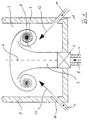
- FIG. 2 shows a furnace similar to that shown in FIG. 1 Furnace shown, the same parts with the same reference numerals are provided.
- the combustion chamber is considered Fluid is not supplied with gas but an evaporable liquid.
- the arrangement of the nozzles 13 in a sufficiently uniform distribution around the central axis 6 of the flame causes the toroidal Annular vortices on the entire circumference of the flame 2 with evaporable Liquid is doped and cooled accordingly, whereby by a corresponding inclination of the nozzles 13 towards one another the flame axis 6 ensures that the injected liquid is injected as precisely as possible to the point at which the Ring vortex arises.
- the invention has the advantage that independent on the type of combustion control, i.e. diffusive, partially premixed or fully premixed, occurring pressure vibrations are to be avoided by the periodic abreaction or combustion toroidal, laminar or turbulent depending on the flow Ring vertebrae are energetically maintained or strengthened.
Claims (17)
- Procédé pour supprimer des vibrations par flamme et par pression dans un four comprenant un brûleur (1) par lequel une flamme (2) est engendrée, et une chambre de combustion (3) vers laquelle ladite flamme (2) est dirigée,
caractérisé par le fait que la chambre de combustion (3) reçoit un fluide (11, 14) venant rencontrer la flamme dans la région de tourbillons annulaires toroïdaux (7), se formant périodiquement sur ladite flamme (2) dans la zone extérieure, de façon telle qu'il soit inclus dans lesdits tourbillons lors de la formation de ces derniers, sachant que le fluide est un gaz (11) ou un liquide vaporisable (14), et présente une teneur en combustible et une température telles que le mélange combustible/air/fluide, se formant dans le tourbillon annulaire, se situe à l'extérieur des limites d'inflammabilité tributaires de la température et de la teneur en combustible. - Procédé selon la revendication 1,
caractérisé par le fait que le fluide (11, 14) est délivré en mode continu. - Procédé selon la revendication 1,
caractérisé par le fait que le fluide (11, 14) est délivré avec répartition uniforme sur le pourtour de la flamme (2). - Procédé selon la revendication 1,
caractérisé par le fait que le gaz (11) est de l'air. - Procédé selon la revendication 1,
caractérisé par le fait que le gaz (11) est délivré, pour l'essentiel, tangentiellement par rapport au tourbillon (7). - Procédé selon la revendication 1,
caractérisé par le fait que le liquide (14) est de l'eau. - Procédé selon la revendication 1,
caractérisé par le fait que l'e liquide (14) est du combustible liquide. - Procédé selon la revendication 1,
caractérisé par le fait que l'injection du liquide (14), dans la chambre de combustion (3), est dirigée vers le site de formation des tourbillons annulaires (7). - Procédé selon la revendication 1,
caractérisé par le fait que le liquide (14) est atomisé lors de l'injection dans la chambre de combustion (3). - Four comprenant un brûleur (1) par lequel une flamme (2) est engendrée, et une chambre de combustion (3) vers laquelle ladite flamme (2) est dirigée, pour la mise en oeuvre du procédé selon la revendication 1,
caractérisé par le fait qu'il comporte des amenées (10, 13) en vue de la délivrance d'un fluide venant rencontrer la flamme dans la région de tourbillons annulaires toroïdaux (7), se formant périodiquement sur ladite flamme (2) dans la zone extérieure, de façon telle qu'il soit inclus dans lesdits tourbillons lors de la formation de ces derniers, sachant que le fluide est un gaz (11) ou un liquide vaporisable (14), et présente une teneur en combustible et une température telles que le mélange combustible/air/fluide, se formant dans le tourbillon annulaire (7), se situe à l'extérieur des limites d'inflammabilité tributaires de la température et de la teneur en combustible. - Four selon la revendication 10,
caractérisé par le fait que les amenées (10, 13) sont agencées uniformément autour d'un axe médian (6) de la flamme (2). - Four selon la revendication 10,
caractérisé par le fait que les amenées (10, 13) sont disposées dans les parois latérales (9) de la chambre de combustion (3). - Four selon la revendication 10,
caractérisé par le fait que les amenées (10, 13) présentent une inclinaison vis-à-vis de l'axe (6) de la flamme. - Four selon la revendication 10,
caractérisé par le fait que les amenées (10) sont des orifices de sortie de gaz. - Four selon la revendication 10,
caractérisé par le fait que les amenées (13) sont des buses destinées à des liquides vaporisables. - Four selon la revendication 15,
caractérisé par le fait que les buses sont des buses de diffusion, dont le jet est dirigé vers le tourbillon annulaire (7). - Four selon la revendication 15,
caractérisé par le fait que les buses sont des buses d'atomisation.
Applications Claiming Priority (4)
| Application Number | Priority Date | Filing Date | Title |
|---|---|---|---|
| DE19604384A DE19604384A1 (de) | 1996-02-07 | 1996-02-07 | Verfahren und Vorrichtung zur Unterdrückung von Flammen-/Druckschwingungen bei einer Feuerung |
| DE1996104385 DE19604385A1 (de) | 1996-02-07 | 1996-02-07 | Verfahren und Vorrichtung zur Unterdrückung von Flammen-/Druckschwingungen bei einer Feuerung |
| DE19604385 | 1996-02-07 | ||
| DE19604384 | 1996-02-07 |
Publications (3)
| Publication Number | Publication Date |
|---|---|
| EP0789193A2 EP0789193A2 (fr) | 1997-08-13 |
| EP0789193A3 EP0789193A3 (fr) | 1998-08-19 |
| EP0789193B1 true EP0789193B1 (fr) | 2002-04-10 |
Family
ID=26022695
Family Applications (1)
| Application Number | Title | Priority Date | Filing Date |
|---|---|---|---|
| EP97100753A Expired - Lifetime EP0789193B1 (fr) | 1996-02-07 | 1997-01-18 | Procédé et dispositif pour supprimer des vibrations par flamme et par pression dans un four |
Country Status (4)
| Country | Link |
|---|---|
| EP (1) | EP0789193B1 (fr) |
| JP (1) | JPH09310818A (fr) |
| AT (1) | ATE216052T1 (fr) |
| DE (1) | DE59706924D1 (fr) |
Families Citing this family (5)
| Publication number | Priority date | Publication date | Assignee | Title |
|---|---|---|---|---|
| WO1999063276A1 (fr) * | 1998-06-04 | 1999-12-09 | Siemens Aktiengesellschaft | Injecteur de combustible et procede pour injecter un jet de combustible |
| DE19831933C1 (de) * | 1998-07-16 | 2000-01-27 | Viessmann Werke Kg | Verfahren und Brenner zur Vermeidung von thermoakustischen Flamm- bzw. Druckschwingungen in mit gebläseunterstützten Brennern betriebenen Feuerungen |
| DE10000415A1 (de) * | 2000-01-07 | 2001-09-06 | Alstom Power Schweiz Ag Baden | Verfahren und Vorrichtung zur Unterdrückung von Strömungswirbeln innerhalb einer Strömungskraftmaschine |
| CN1294380C (zh) * | 2003-12-09 | 2007-01-10 | 财团法人工业技术研究院 | 一种燃烧器 |
| US8096804B2 (en) * | 2008-04-30 | 2012-01-17 | IFP Energies Nouvelles | Device for controlling the radial profile of the temperature of a confined gas stream |
Family Cites Families (3)
| Publication number | Priority date | Publication date | Assignee | Title |
|---|---|---|---|---|
| US4863371A (en) * | 1988-06-03 | 1989-09-05 | Union Carbide Corporation | Low NOx high efficiency combustion process |
| CH682009A5 (fr) * | 1990-11-02 | 1993-06-30 | Asea Brown Boveri | |
| DE4308731A1 (de) * | 1993-03-19 | 1994-09-22 | Babcock Omnical Gmbh | Verfahren zur Verminderung der Bildung von NOx und Kessel |
-
1997
- 1997-01-18 EP EP97100753A patent/EP0789193B1/fr not_active Expired - Lifetime
- 1997-01-18 DE DE59706924T patent/DE59706924D1/de not_active Expired - Lifetime
- 1997-01-18 AT AT97100753T patent/ATE216052T1/de not_active IP Right Cessation
- 1997-02-07 JP JP9024194A patent/JPH09310818A/ja active Pending
Also Published As
| Publication number | Publication date |
|---|---|
| EP0789193A3 (fr) | 1998-08-19 |
| EP0789193A2 (fr) | 1997-08-13 |
| JPH09310818A (ja) | 1997-12-02 |
| ATE216052T1 (de) | 2002-04-15 |
| DE59706924D1 (de) | 2002-05-16 |
Similar Documents
| Publication | Publication Date | Title |
|---|---|---|
| EP0638769B1 (fr) | Injecteur de combustible pour des combustibles liquides et gazeux et procédé de sa mise en oeuvre | |
| DE60007946T2 (de) | Eine Brennkammer | |
| DE60025933T2 (de) | Brennvorrichtung zur behandlung von abgas | |
| EP0503319B1 (fr) | Brûleur pour une combustion à mélange préalable d'un combustible liquide et/ou gazeux | |
| WO1999037951A1 (fr) | Dispositif permettant de supprimer les oscillations de la flamme/pression dans un foyer, notamment une turbine a gaz | |
| EP0754908B1 (fr) | Procédé et dispositif pour supprimer des vibrations par flamme et par pression dans un four | |
| DE2653404A1 (de) | Verfahren und brenner zum verbrennen von fluessigem brennstoff, insbesondere oel | |
| DE112011103722T5 (de) | Brennkammer für Gasturbine für niederkalorischen Teibstoff | |
| DE1153330B (de) | Nebelkammer | |
| DE2953648C2 (de) | Flüssigbrennstoffbrenner | |
| EP0394800A1 (fr) | Brûleur à mélange préalable pour la génération de gaz chaud | |
| EP1754937B1 (fr) | Tête de brûleur et procédé pour brûler du combustible | |
| EP0857915B1 (fr) | Procédé et tête de brûleur pour la combustion des combustibles liquides ou gazeux | |
| EP0346284B1 (fr) | Brûleur pour la combustion de combustibles liquides en état gazeux | |
| EP0483554B1 (fr) | Procédé pour la réduction au minimum des émissions de NOx dans une combustion | |
| EP0789193B1 (fr) | Procédé et dispositif pour supprimer des vibrations par flamme et par pression dans un four | |
| EP1084368A1 (fr) | Injecteur de combustible | |
| EP0602396A1 (fr) | Générateur de chaleur pour processus industriel | |
| DE4422535A1 (de) | Verfahren zum Betrieb einer Feuerungsanlage | |
| EP0703413B1 (fr) | Chambre de combustion d'une turbine à gaz | |
| DE4408256A1 (de) | Verfahren und Vorrichtung zur Flammenstabilisation von Vormischbrennern | |
| DE19604385A1 (de) | Verfahren und Vorrichtung zur Unterdrückung von Flammen-/Druckschwingungen bei einer Feuerung | |
| DE4436728A1 (de) | Verfahren und Vorrichtung für eine schadstoffarme gestufte Verbrennung | |
| EP0543155B1 (fr) | Procédé pour une combustion peu polluante dans une chaudère de centrale électrique | |
| DE19531387C2 (de) | Verfahren zum Verbrennen insbesondere flüssiger Brennstoffe und Brenner zur Durchführung des Verfahrens |
Legal Events
| Date | Code | Title | Description |
|---|---|---|---|
| PUAI | Public reference made under article 153(3) epc to a published international application that has entered the european phase |
Free format text: ORIGINAL CODE: 0009012 |
|
| AK | Designated contracting states |
Kind code of ref document: A2 Designated state(s): AT BE CH DE DK ES FR GB IT LI LU NL PT SE |
|
| PUAL | Search report despatched |
Free format text: ORIGINAL CODE: 0009013 |
|
| AK | Designated contracting states |
Kind code of ref document: A3 Designated state(s): AT BE CH DE DK ES FR GB IT LI LU NL PT SE |
|
| 17P | Request for examination filed |
Effective date: 19980904 |
|
| 17Q | First examination report despatched |
Effective date: 20001222 |
|
| GRAG | Despatch of communication of intention to grant |
Free format text: ORIGINAL CODE: EPIDOS AGRA |
|
| GRAG | Despatch of communication of intention to grant |
Free format text: ORIGINAL CODE: EPIDOS AGRA |
|
| GRAH | Despatch of communication of intention to grant a patent |
Free format text: ORIGINAL CODE: EPIDOS IGRA |
|
| GRAH | Despatch of communication of intention to grant a patent |
Free format text: ORIGINAL CODE: EPIDOS IGRA |
|
| REG | Reference to a national code |
Ref country code: GB Ref legal event code: IF02 |
|
| GRAA | (expected) grant |
Free format text: ORIGINAL CODE: 0009210 |
|
| AK | Designated contracting states |
Kind code of ref document: B1 Designated state(s): AT BE CH DE DK ES FR GB IT LI LU NL PT SE |
|
| PG25 | Lapsed in a contracting state [announced via postgrant information from national office to epo] |
Ref country code: NL Free format text: LAPSE BECAUSE OF FAILURE TO SUBMIT A TRANSLATION OF THE DESCRIPTION OR TO PAY THE FEE WITHIN THE PRESCRIBED TIME-LIMIT Effective date: 20020410 Ref country code: IT Free format text: LAPSE BECAUSE OF FAILURE TO SUBMIT A TRANSLATION OF THE DESCRIPTION OR TO PAY THE FEE WITHIN THE PRESCRIBED TIME-LIMIT;WARNING: LAPSES OF ITALIAN PATENTS WITH EFFECTIVE DATE BEFORE 2007 MAY HAVE OCCURRED AT ANY TIME BEFORE 2007. THE CORRECT EFFECTIVE DATE MAY BE DIFFERENT FROM THE ONE RECORDED. Effective date: 20020410 |
|
| REF | Corresponds to: |
Ref document number: 216052 Country of ref document: AT Date of ref document: 20020415 Kind code of ref document: T |
|
| REG | Reference to a national code |
Ref country code: CH Ref legal event code: EP |
|
| REF | Corresponds to: |
Ref document number: 59706924 Country of ref document: DE Date of ref document: 20020516 |
|
| PG25 | Lapsed in a contracting state [announced via postgrant information from national office to epo] |
Ref country code: SE Free format text: LAPSE BECAUSE OF FAILURE TO SUBMIT A TRANSLATION OF THE DESCRIPTION OR TO PAY THE FEE WITHIN THE PRESCRIBED TIME-LIMIT Effective date: 20020710 Ref country code: PT Free format text: LAPSE BECAUSE OF FAILURE TO SUBMIT A TRANSLATION OF THE DESCRIPTION OR TO PAY THE FEE WITHIN THE PRESCRIBED TIME-LIMIT Effective date: 20020710 Ref country code: DK Free format text: LAPSE BECAUSE OF FAILURE TO SUBMIT A TRANSLATION OF THE DESCRIPTION OR TO PAY THE FEE WITHIN THE PRESCRIBED TIME-LIMIT Effective date: 20020710 |
|
| GBT | Gb: translation of ep patent filed (gb section 77(6)(a)/1977) |
Effective date: 20020708 |
|
| NLV1 | Nl: lapsed or annulled due to failure to fulfill the requirements of art. 29p and 29m of the patents act | ||
| ET | Fr: translation filed | ||
| PG25 | Lapsed in a contracting state [announced via postgrant information from national office to epo] |
Ref country code: ES Free format text: LAPSE BECAUSE OF FAILURE TO SUBMIT A TRANSLATION OF THE DESCRIPTION OR TO PAY THE FEE WITHIN THE PRESCRIBED TIME-LIMIT Effective date: 20021030 |
|
| PG25 | Lapsed in a contracting state [announced via postgrant information from national office to epo] |
Ref country code: LU Free format text: LAPSE BECAUSE OF NON-PAYMENT OF DUE FEES Effective date: 20030118 Ref country code: AT Free format text: LAPSE BECAUSE OF NON-PAYMENT OF DUE FEES Effective date: 20030118 |
|
| PG25 | Lapsed in a contracting state [announced via postgrant information from national office to epo] |
Ref country code: LI Free format text: LAPSE BECAUSE OF NON-PAYMENT OF DUE FEES Effective date: 20030131 Ref country code: CH Free format text: LAPSE BECAUSE OF NON-PAYMENT OF DUE FEES Effective date: 20030131 Ref country code: BE Free format text: LAPSE BECAUSE OF NON-PAYMENT OF DUE FEES Effective date: 20030131 |
|
| PLBE | No opposition filed within time limit |
Free format text: ORIGINAL CODE: 0009261 |
|
| STAA | Information on the status of an ep patent application or granted ep patent |
Free format text: STATUS: NO OPPOSITION FILED WITHIN TIME LIMIT |
|
| 26N | No opposition filed |
Effective date: 20030113 |
|
| REG | Reference to a national code |
Ref country code: CH Ref legal event code: PL |
|
| PGFP | Annual fee paid to national office [announced via postgrant information from national office to epo] |
Ref country code: GB Payment date: 20090123 Year of fee payment: 13 |
|
| PGFP | Annual fee paid to national office [announced via postgrant information from national office to epo] |
Ref country code: FR Payment date: 20090120 Year of fee payment: 13 |
|
| GBPC | Gb: european patent ceased through non-payment of renewal fee |
Effective date: 20100118 |
|
| REG | Reference to a national code |
Ref country code: FR Ref legal event code: ST Effective date: 20100930 |
|
| PG25 | Lapsed in a contracting state [announced via postgrant information from national office to epo] |
Ref country code: FR Free format text: LAPSE BECAUSE OF NON-PAYMENT OF DUE FEES Effective date: 20100201 |
|
| PG25 | Lapsed in a contracting state [announced via postgrant information from national office to epo] |
Ref country code: GB Free format text: LAPSE BECAUSE OF NON-PAYMENT OF DUE FEES Effective date: 20100118 |
|
| PGFP | Annual fee paid to national office [announced via postgrant information from national office to epo] |
Ref country code: DE Payment date: 20110126 Year of fee payment: 15 |
|
| PG25 | Lapsed in a contracting state [announced via postgrant information from national office to epo] |
Ref country code: DE Free format text: LAPSE BECAUSE OF NON-PAYMENT OF DUE FEES Effective date: 20120801 |
|
| REG | Reference to a national code |
Ref country code: DE Ref legal event code: R119 Ref document number: 59706924 Country of ref document: DE Effective date: 20120801 |
|
| REG | Reference to a national code |
Ref country code: DE Ref legal event code: R082 Ref document number: 59706924 Country of ref document: DE Representative=s name: PETERSEN, FRANK, DIPL.-ING., DE |