EP0788863B1 - Combustion powered fastener driving tool - Google Patents
Combustion powered fastener driving tool Download PDFInfo
- Publication number
- EP0788863B1 EP0788863B1 EP97300664A EP97300664A EP0788863B1 EP 0788863 B1 EP0788863 B1 EP 0788863B1 EP 97300664 A EP97300664 A EP 97300664A EP 97300664 A EP97300664 A EP 97300664A EP 0788863 B1 EP0788863 B1 EP 0788863B1
- Authority
- EP
- European Patent Office
- Prior art keywords
- cylinder
- piston
- tool
- combustion
- fastener
- Prior art date
- Legal status (The legal status is an assumption and is not a legal conclusion. Google has not performed a legal analysis and makes no representation as to the accuracy of the status listed.)
- Expired - Lifetime
Links
- 238000002485 combustion reaction Methods 0.000 title claims description 72
- 238000006073 displacement reaction Methods 0.000 claims description 22
- 238000002955 isolation Methods 0.000 claims description 5
- 239000000758 substrate Substances 0.000 description 11
- 239000007789 gas Substances 0.000 description 9
- 230000009467 reduction Effects 0.000 description 9
- 238000012546 transfer Methods 0.000 description 7
- 238000013461 design Methods 0.000 description 5
- 239000000446 fuel Substances 0.000 description 5
- 230000001133 acceleration Effects 0.000 description 4
- 230000004044 response Effects 0.000 description 4
- 235000014676 Phragmites communis Nutrition 0.000 description 3
- 229910000831 Steel Inorganic materials 0.000 description 3
- 238000010304 firing Methods 0.000 description 3
- 239000007787 solid Substances 0.000 description 3
- 239000010959 steel Substances 0.000 description 3
- 238000013459 approach Methods 0.000 description 2
- QVGXLLKOCUKJST-UHFFFAOYSA-N atomic oxygen Chemical compound [O] QVGXLLKOCUKJST-UHFFFAOYSA-N 0.000 description 2
- 238000006243 chemical reaction Methods 0.000 description 2
- 239000002737 fuel gas Substances 0.000 description 2
- 238000012423 maintenance Methods 0.000 description 2
- 239000001301 oxygen Substances 0.000 description 2
- 229910052760 oxygen Inorganic materials 0.000 description 2
- 239000000843 powder Substances 0.000 description 2
- 230000002829 reductive effect Effects 0.000 description 2
- 239000002023 wood Substances 0.000 description 2
- 230000009471 action Effects 0.000 description 1
- 230000002411 adverse Effects 0.000 description 1
- 230000004075 alteration Effects 0.000 description 1
- 239000006227 byproduct Substances 0.000 description 1
- 230000002860 competitive effect Effects 0.000 description 1
- 230000007423 decrease Effects 0.000 description 1
- 238000005516 engineering process Methods 0.000 description 1
- 238000004880 explosion Methods 0.000 description 1
- 239000002360 explosive Substances 0.000 description 1
- 239000012530 fluid Substances 0.000 description 1
- 239000003721 gunpowder Substances 0.000 description 1
- 230000007246 mechanism Effects 0.000 description 1
- 239000002184 metal Substances 0.000 description 1
- 238000000034 method Methods 0.000 description 1
- 239000000203 mixture Substances 0.000 description 1
- 230000004048 modification Effects 0.000 description 1
- 238000012986 modification Methods 0.000 description 1
- 210000002445 nipple Anatomy 0.000 description 1
- 230000036961 partial effect Effects 0.000 description 1
- 230000002093 peripheral effect Effects 0.000 description 1
- 230000008569 process Effects 0.000 description 1
- VBUBYMVULIMEHR-UHFFFAOYSA-N propa-1,2-diene;prop-1-yne Chemical compound CC#C.C=C=C VBUBYMVULIMEHR-UHFFFAOYSA-N 0.000 description 1
- 239000003380 propellant Substances 0.000 description 1
- 230000000717 retained effect Effects 0.000 description 1
- 230000002000 scavenging effect Effects 0.000 description 1
- 238000007789 sealing Methods 0.000 description 1
- 230000000087 stabilizing effect Effects 0.000 description 1
Images

Classifications
-
- B—PERFORMING OPERATIONS; TRANSPORTING
- B25—HAND TOOLS; PORTABLE POWER-DRIVEN TOOLS; MANIPULATORS
- B25C—HAND-HELD NAILING OR STAPLING TOOLS; MANUALLY OPERATED PORTABLE STAPLING TOOLS
- B25C1/00—Hand-held nailing tools; Nail feeding devices
- B25C1/08—Hand-held nailing tools; Nail feeding devices operated by combustion pressure
- B25C1/10—Hand-held nailing tools; Nail feeding devices operated by combustion pressure generated by detonation of a cartridge
- B25C1/18—Details and accessories, e.g. splinter guards, spall minimisers
- B25C1/188—Arrangements at the forward end of the barrel, e.g. splinter guards, spall minimisers, safety arrangements, silencers, bolt retainers
-
- B—PERFORMING OPERATIONS; TRANSPORTING
- B25—HAND TOOLS; PORTABLE POWER-DRIVEN TOOLS; MANIPULATORS
- B25C—HAND-HELD NAILING OR STAPLING TOOLS; MANUALLY OPERATED PORTABLE STAPLING TOOLS
- B25C1/00—Hand-held nailing tools; Nail feeding devices
- B25C1/08—Hand-held nailing tools; Nail feeding devices operated by combustion pressure
Definitions
- the present invention relates generally to improvements in portable combustion powered fastener driving tools, and specifically to improvements relating to the control of power output and the maintenance of stable alignment of such a tool over a workpiece.
- IMPULSE brand tools for use in driving fasteners into workpieces are described in commonly assigned patents to Nikolich U.S.Pat.Re.No.32,452, and U.S.Pat.Nos.4,522, 162, 4, 483,473, 4,483,474, 4,403,722, and 5,263,439.
- Combustion powered nail and staple driving tools based on these are available commercially from ITW-Paslode of Lincolnshire, Illinois, USA, under the IMPULSE® brand.
- Such tools incorporate a tool housing enclosing a small internal combustion engine.
- the engine is powered by a canister of pressurized fuel gas, also called a fuel cell.
- a battery-powered electronic power distribution unit produces the spark for ignition, and a fan located in the combustion chamber provides for both an efficient combustion within the chamber, and facilitates scavenging, including the exhaust of combustion byproducts.
- the engine includes a reciprocating piston with an elongate, rigid driver blade disposed within a piston chamber of a cylinder body.
- a valve sleeve is axially reciprocable about the cylinder and, through a linkage, moves to close the combustion chamber when a work contact element at the end of the linkage is pressed against a workpiece. This pressing action also triggers a fuel metering valve to introduce a specified volume of fuel gas into the closed combustion chamber.
- the piston and driver blade Upon the pulling of a trigger switch, which causes the ignition of a charge of gas in the combustion chamber of the engine, the piston and driver blade are shot downward to impact a positioned fastener and drive it into the workpiece.
- a displacement volume enclosed in the piston chamber below the piston is forced to exit through one or more exit ports provided at a lower end of the cylinder.
- the piston After impact, the piston then returns to its original, or "ready” position through differential gas pressures within the cylinder.
- Fasteners are fed magazine-style into the nosepiece, where they are held in a properly positioned orientation for receiving the impact of the driver blade.
- Combustion powered tools may be contrasted from conventional powder activated technology (PAT) tools, which employ a gunpowder powered cartridge to propel a driving member to drive a fastener into a workpiece.
- PAT tools generate an explosion in a combustion chamber which creates high pressures for propelling the driving member at a high velocity toward the fastener.
- the relatively small volume of the combustion chamber and the explosive combustion combine to create a rapid acceleration of the driving member for the velocity required for proper fastener driving.
- combustion powered tools typically provide a much slower acceleration of the driving member. This is due to the relatively large size of the combustion chamber, and to the requirement of the preferred fuel to obtain atmospheric oxygen for combustion (the powder in PAT tools incorporates its own oxygen).
- the combustion event is a relatively gradual process.
- Commercially available combustion powered tools have relatively short cylinder bodies, so the driving member is incapable of achieving velocities which are comparable to those of PAT tools.
- a high velocity combustion powered tool of the type described above and featuring an extended piston chamber or cylinder is the subject of EP-A-0765715.
- the extended cylinder increases the stroke of the piston, thereby allowing for increased piston velocity and transfer of power from the driver blade to the fastener.
- the extended length also allows an operator to stand generally upright while driving fasteners which are at foot level.
- piston velocity A number of factors influence piston velocity, including piston diameter and stroke, but these factors are fixed by design in a given tool.
- One way to vary the power of a combustion powered tool is by means of controlling the speed of the fan on the combustion chamber, as described in EP-A-711634.
- a circuit is used to vary fan speed, and increased fan speed produces additional power.
- the piston velocity is fixed by design.
- the fixed piston velocity prevents an operator from controlling the driving depth of the fastener being driven into a particular type of workpiece or substrate.
- the lack of velocity control may prevent an operator from obtaining a consistent desired driving depth.
- An identical driver blade velocity when translated into force applied to a fastener being driven into wood, for instance, will result in a different depth when applied to a fastener being driven into a steel beam. Such velocity will result in still another depth when applied to a fastener being driven into sheet metal being fastened to a roof truss.
- Drawbacks of such operation are misaligned or incompletely driven fasteners.
- US-A-5263842 describes a fluid pressure operated nailer with a two-piece nosepiece the two parts of which are biased apart by a spring.
- the spring is compressed before the nailer is operated and recoil of the body results in only the part of the nosepiece attached to the body moving in the recoil direction.
- the spring maintains the other part of the nosepiece in contact with the workpiece.
- US-A-4403722 describes a combustion powered tool having a self-contained internal combustion power source constructed and arranged for creating combustion for driving a driver blade to impact a fastener and drive it into a workpiece, comprising a housing having a main chamber enclosing the power source; a cylinder within said main chamber enclosing a piston for driving the driver blade the length of said cylinder, advancement of said piston displacing a displacement volume of air disposed in said cylinder on one side of said piston; and, at least one displacement volume exit port disposed in said cylinder for allowing said displacement volume of air to exit the cylinder when displayed by the advancing piston.
- such a combustion powered tool also includes adjusting means for adjusting the resistance to the exit of said displacement volume of air from said cylinder through said at least one exit port.
- a preferred embodiment of tool allows for adjustment of effective exit port size through which a displaced air volume exits the cylinder as the piston and driver blade advances down the cylinder toward impact with a fastener.
- One or more exit ports are provided near a terminal end of the cylinder.
- An exit port adjustment ring circumscribes the cylinder and has openings corresponding to the exit ports. In a first position, the openings align with the exit ports so that exit ports are fully exposed. Rotatable adjustment of the ring to other positions will cause portions of the ring to partially block the exit ports, thereby reducing their effective size.
- the effective size of the exit ports is reduced, resistance to the flow of displacement volume out of the cylinder increases, and creates a corresponding increase in resistance to the travel of the piston toward the terminal end of the piston chamber.
- the velocity of the piston and the subsequent applied impact force may be reduced incrementally by successively reducing the effective size of the exit ports via adjustment of the ring.
- the embodiment provides a combustion powered tool having a self-contained internal combustion power source constructed and arranged for creating a combustion event for driving a driver blade to impact a fastener and drive it into a workpiece.
- the tool includes a housing having a main chamber enclosing the power source, and a cylinder within the main chamber enclosing piston for driving the driver blade the length of the cylinder. Advancement of the piston displaces a displacement volume of air disposed in the cylinder on one side of the piston.
- the tool also includes at least one displacement volume exit port disposed in the cylinder for allowing the displacement volume to exit the cylinder when displaced by the advancing piston, and features an adjusting device for adjusting resistance to the exit of the displacement volume from the cylinder through the at least one exit port.
- the nosepiece which guides the driver blade to strike a fastener remains in position against the workpiece upon combustion and until the fastener is struck, even when an extended length cylinder is used.
- the nosepiece is mechanically isolated from the piston chamber and the remaining portions of the tool.
- a preferred structure for effecting the mechanical isolation is at least one spring.
- One or more springs disposed between the nosepiece and the remaining portions of the tool absorb tool recoil occurring in response to the combustion which drives the piston. While combustion may cause the remainder of the tool to move with respect to the fastener and workpiece or substrate, the spring separates the nosepiece from the movement so that the nosepiece remains stationary with respect to the fastener and substrate until impact.
- a main housing 12 of the tool 10 encloses a self contained internal power source 16.
- the power source includes a combustion chamber 20 that communicates with a cylinder 22.
- a piston 24, including exhaust gas cutouts 26, is disposed within the cylinder 22 and is connected to a driver blade 28.
- the cylinder 22 is of the extended length type and as such is considerably longer than the driver blade 28.
- a peripheral lower edge of the piston 24 includes at least one piston ring (not shown) for creating a seal with inner walls of the piston chamber 22.
- an operator induces combustion of a measured amount of propellant, such as MAPP gas, within the combustion chamber 20.
- a measured amount of propellant such as MAPP gas
- the piston 24 is driven toward a terminal end 32 of the cylinder 22.
- the driver blade 28 will be guided into a nosepiece 34 and impact a fastener (not shown) held above a workpiece by the nosepiece.
- the fastener be of the so-called pin type, described in more detail in U.S. Patent No. 5,199,625. Impact of the driver blade 28 drives the fastener into a workpiece or substrate.
- a displaced volume of air V is defined within the cylinder 22, and below a lower side 27 of the piston 24.
- the air in volume V is driven down the cylinder 22 and out through displacement volume exit ports 40 and through exhaust ports 41 by the advancement of the piston 24 toward the terminal end 32 of the cylinder 22.
- a bumper 42 defines the end of travel of the piston 24 toward the terminal end 32.
- the exhaust ports 41 are exposed to the outside under control of a reed valve (not shown), or other suitable type of valve, located in a port 44.
- the displacement volume V will have exited through either the exit ports 40, which are located below the terminal end 32, or through the exhaust ports 41.
- the displacement volume V can only exit the exhaust ports 41 prior to the piston passing the ports 41 as it advances toward the terminal end 32.
- the tool 10 illustrated in FIG 1 is a so-called extended length cylinder embodiment.
- the extended length cylinder 22 allows an operator standing generally upright to operate the tool 10 to drive fasteners at foot level.
- An important additional feature of the extended length tool 10 is the increase in the stroke of the piston 24. Through the increased stroke, velocity of the piston at impact and efficiency of power transfer is enhanced, when compared to an otherwise identical combustion powered tool having a smaller stroke.
- a known standard length cylinder tool available commercially from ITW-Paslode of Lincolnshire, Illinois has a stroke of approximately 3.5 inches (90 mm).
- the combustion chamber volume is approximately 17 cubic inches (0.28 l) .
- an available approximately 120 joules of energy available at combustion such a tool imparts approximately 41.7% (about 50 joules) to a fastener.
- an extended cylinder tool with a stroke of approximately 7 inches (180 mm) imparts approximately 83.3% of the available 120 joules to a fastener.
- combustion powered tools may now achieve driver blade velocities which are comparable to those of PAT tools, which typically have high pressure and greater driver blade velocity.
- the cylinder 22 in the extended length tool has a length exceeding that of the driver blade 28.
- at least two vertically extending stabilizing members 47 of the piston 24 contact the inner wall of the piston chamber 22.
- the efficiency of energy transfer and piston velocity in a given standard or extended cylinder tool is fixed by design. Between two different combustion powered tools, stroke may be different and the separate tools might thereby develop different piston velocity and energy transfer efficiency.
- altering the piston diameter, piston weight, combustion chamber volume, and initial combustion chamber pressure between two tool designs could alter the velocity and energy transfer between the tools.
- the tool 10 of the present invention includes an exit port size adjustment ring 48 (best seen in Figure 2).
- the adjustment ring 48 fits over an outer sleeve 50.
- the sleeve 50 is snugly attached to an outer surface 54 of the cylinder 22, and includes circumferentially spaced holes 52 which correspond to the exit ports 40.
- circumferentially spaced exit port openings 56 disposed between solid portions 58 of the adjustment ring 48 may be aligned with both the exit ports 40 and the holes 52.
- the adjustment ring is checkered to provide a positive gripping surface.
- the adjustment ring 48 includes a plurality of laterally spaced positioning holes 60 configured and disposed to be engaged by a short pin 62 extending radially from an outer surface of the sleeve 50.
- Each of the separate positioning holes 60 represents a distinct rotational position of the adjustment ring 48.
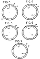
- One of the positioning holes 60 may align the exit port openings 56 exactly with the exit ports 40. In this position, (best seen in Figure 3) the exit ports 40 will be fully exposed, and the effective size of the exit ports 40 is at a maximum.
- FIGs 4-7 Successive reductions of the effective size of the exit ports 40 are illustrated schematically in Figures 4-7.
- the adjustment ring 48 is moved in a counterclockwise manner, successive reductions of exit port effective size are obtained through varying degrees of alignment of the solid portions 58 of the adjustment ring 48 with the exit ports 40.
- the solid portions 58 progressively cover, to an increasing degree, the exit ports 40.
- Each reduction of effective exit port size further restricts the path for flow of the displacement volume V out through the exit ports 40.
- Each reduction in exposure of the exit ports 40 reduces the effective size of the exits ports, and serves to reduce piston velocity.
- the exit ports 40 are essentially closed and as such provide the maximum reduction in piston velocity.
- an additional feature of the invention concerns the maintenance of the stability of the tool 10 with respect to a workpiece or substrate until the driver blade 28 strikes a fastener. If the tool moves with respect to the workpiece or substrate prior to impact, the transfer of power to the fastener, and angle of contact between the nosepiece 34 and the fastener may be adversely affected. Stability may be especially difficult to maintain in the extended length cylinder tools.
- the piston 24 takes a longer time to travel to the terminal end 32 when compared to a shorter cylinder tool, and recoil of the tool 10 in response to the combustion can occur before the piston has completed its travel, and before the driver blade 28 strikes the fastener.
- the nosepiece 34 which positions and holds fasteners is mechanically isolated from the recoil of the remaining portions of the tool 10.
- At least one, and preferably a plurality of springs 64 allow the cylinder 22 to move independently of the nosepiece 34 within a limited range, while the nosepiece remains stable.
- Each spring 64 is retained about a vertical lug 65 on the nosepiece 34.
- Set screws 66 attach a cylinder closure 68 to the sleeve 50 so that the cylinder closure will move with the sleeve 50 and cylinder 22.
- the bumper 42 threads onto a nipple 69 of the nosepiece 34, with a flange 70 of the bumper pressing against a shoulder 72 of the cylinder closure 68.
- the stopper 42 and nosepiece 34 are mechanically isolated from this movement by the springs 64 and remain stable.
- the isolation serves to hold the nosepiece 34 and bumper 64 stable, even where the remaining portions of the tool 10 experience combustion recoil prior to impact of the driver blade 28 with a fastener.
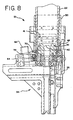
- FIG. 8 This aspect of the invention is further illustrated in Figures 8 and 9.
- the cylinder closure compresses the springs 64 in response to pressure applied by the operator in aligning the tool 10 for firing.
- the shoulder 72 moves downward and separates from the flange 70.
- the nosepiece 34 and stopper 42 remain stationary as the springs 64 become compressed.
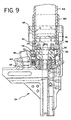
- Figure 9 the situation upon combustion is indicated. Due to combustion-generated recoil, the springs 64 decompress, pushing the cylinder 22 and attached components upward. While the springs 64 relax, the driver blade 28 is allowed time to impact a fastener.
- the upward movement of the cylinder is terminated by the engagement of the shoulder 72 against the flange 70.
- the nosepiece 34 and the stopper 42 remain stationary against the workpiece even during combustion. In this manner, the driver blade 28 is allowed sufficient time to travel down the cylinder, impact the fastener, and accurately drive it into the workpiece.
- features of the present invention provide for user controlled adjustments to piston velocity, as well as mechanical isolation of the tool nosepiece to increase accuracy of fastener placement.
Landscapes
- Engineering & Computer Science (AREA)
- Chemical & Material Sciences (AREA)
- Combustion & Propulsion (AREA)
- Mechanical Engineering (AREA)
- Portable Nailing Machines And Staplers (AREA)
Applications Claiming Priority (2)
| Application Number | Priority Date | Filing Date | Title |
|---|---|---|---|
| US599022 | 1990-10-17 | ||
| US08/599,022 US5799855A (en) | 1996-02-09 | 1996-02-09 | Velocity control and nosepiece stabilizer system for combustion powered tools |
Publications (2)
| Publication Number | Publication Date |
|---|---|
| EP0788863A1 EP0788863A1 (en) | 1997-08-13 |
| EP0788863B1 true EP0788863B1 (en) | 2004-07-28 |
Family
ID=24397885
Family Applications (1)
| Application Number | Title | Priority Date | Filing Date |
|---|---|---|---|
| EP97300664A Expired - Lifetime EP0788863B1 (en) | 1996-02-09 | 1997-02-03 | Combustion powered fastener driving tool |
Country Status (8)
| Country | Link |
|---|---|
| US (2) | US5799855A (mo) |
| EP (1) | EP0788863B1 (mo) |
| JP (1) | JP4145968B2 (mo) |
| CA (1) | CA2193926C (mo) |
| ES (1) | ES2225933T3 (mo) |
| MX (1) | MX9700396A (mo) |
| NO (1) | NO970492L (mo) |
| TW (1) | TW350807B (mo) |
Families Citing this family (35)
| Publication number | Priority date | Publication date | Assignee | Title |
|---|---|---|---|---|
| FR2774017B1 (fr) * | 1998-01-27 | 2000-03-17 | Spit Soc Prospect Inv Techn | Appareil de fixation a piston propulse par gaz comprime |
| DE19962696C1 (de) * | 1999-12-23 | 2001-06-07 | Hilti Ag | Brennkraftbetriebenes Arbeitsgerät mit Bremseinrichtung für seinen Kolben |
| US6585141B2 (en) * | 1999-12-28 | 2003-07-01 | Textron Inc. | Adjustable-length end piece for a fastener drive tool |
| US6755002B2 (en) * | 2001-10-24 | 2004-06-29 | Nicholas M. Pendrous | Apparatus and method for repairing popped wallboard nails |
| DE10218194B4 (de) * | 2002-04-24 | 2004-05-13 | Hilti Ag | Über expandierende Gase antreibbares Setzgerät |
| DE10228036B4 (de) * | 2002-06-24 | 2014-05-28 | Hilti Aktiengesellschaft | Über expandierende Gase angetriebbares Setzgerät mit Magazin für Befestigungselemente |
| US6695192B1 (en) | 2002-09-30 | 2004-02-24 | Illinois Tool Works Inc. | Adjustable depth control for fastener driving tool |
| FR2852546B1 (fr) * | 2003-03-19 | 2006-08-11 | Prospection & Inventions | Procedes de reglage de la puissance d'un appareil a fonctionnement a gaz |
| US6964553B2 (en) * | 2003-05-23 | 2005-11-15 | Illinois Tool Works Inc. | Port for a fan chamber |
| US6964362B2 (en) | 2004-02-06 | 2005-11-15 | Illinois Tool Works Inc. | Shock-absorbing system for fastener driving tools |
| US7201301B2 (en) | 2004-02-09 | 2007-04-10 | Illinois Tool Works Inc. | Exhaust system for combustion-powered fastener-driving tool |
| FR2870770B1 (fr) * | 2004-05-27 | 2006-08-11 | Prospection Et D Inv S Techniq | Appareil de fixation a gaz a carter de moteur thermique monte flottant a l'avant |
| US8002160B2 (en) | 2004-08-30 | 2011-08-23 | Black & Decker Inc. | Combustion fastener |
| US7314025B2 (en) | 2005-07-15 | 2008-01-01 | Illinois Tool Works Inc. | Combustion powered fastener-driving tool with interconnected chambers |
| USD560108S1 (en) | 2005-07-19 | 2008-01-22 | Milwaukee Electric Tool Corporation | Power tool, such as a nailer |
| JP4984487B2 (ja) * | 2005-10-26 | 2012-07-25 | マックス株式会社 | 空気圧式ネジ打込み機の打込み力調整機構 |
| US8070031B2 (en) * | 2005-11-17 | 2011-12-06 | Illinois Tool Works Inc. | Variable ignition delay for combustion nailer |
| US8104659B2 (en) * | 2006-03-27 | 2012-01-31 | Stanley Black & Decker, Inc. | Electromagnetic stapler with a manually adjustable depth adjuster |
| US7513404B2 (en) * | 2007-04-13 | 2009-04-07 | Illinois Tool Works Inc. | Depth of drive control with load transfer for fastener driver |
| US7753230B2 (en) * | 2007-12-20 | 2010-07-13 | Mikio Kusano | Nut feeder |
| US20090206121A1 (en) * | 2008-02-14 | 2009-08-20 | Araiza Frank L | Power adjustable fastener propelling tool |
| TWM362088U (en) * | 2009-04-09 | 2009-08-01 | Cheng-Ho Lee | Gunpowder nail-hitting apparatus capable of adjusting nail-hitting force |
| US8840002B2 (en) * | 2009-07-01 | 2014-09-23 | Hitachi Koki Co., Ltd. | Fastener-driving tool |
| EP2886258A1 (de) * | 2013-12-18 | 2015-06-24 | HILTI Aktiengesellschaft | Eintreibgerät |
| EP2886257A1 (de) * | 2013-12-18 | 2015-06-24 | HILTI Aktiengesellschaft | Eintreibgerät |
| EP2886260A1 (de) * | 2013-12-19 | 2015-06-24 | HILTI Aktiengesellschaft | Eintreibgerät |
| EP2923800A1 (de) * | 2014-03-28 | 2015-09-30 | HILTI Aktiengesellschaft | Pyrotechnisches Eintreibgerät |
| EP2923797A1 (de) | 2014-03-28 | 2015-09-30 | HILTI Aktiengesellschaft | Pyrotechnisches Eintreibgerät |
| US10759031B2 (en) | 2014-08-28 | 2020-09-01 | Power Tech Staple and Nail, Inc. | Support for elastomeric disc valve in combustion driven fastener hand tool |
| US9862083B2 (en) | 2014-08-28 | 2018-01-09 | Power Tech Staple and Nail, Inc. | Vacuum piston retention for a combustion driven fastener hand tool |
| US10173310B2 (en) | 2015-02-06 | 2019-01-08 | Milwaukee Electric Tool Corporation | Gas spring-powered fastener driver |
| US20180215024A1 (en) * | 2017-01-27 | 2018-08-02 | Craig Carlson | Nail Driving Assembly |
| DE202017103050U1 (de) * | 2017-05-19 | 2018-08-22 | Joh. Friedrich Behrens Ag | Eintreibgerät zum Eintreiben von Befestigungsmitteln in Werkstücke |
| EP3578316A1 (de) * | 2018-06-06 | 2019-12-11 | HILTI Aktiengesellschaft | Setzgerät |
| CA3052627A1 (en) | 2018-08-21 | 2020-02-21 | Power Tech Staple and Nail, Inc. | Combustion chamber valve and fuel system for driven fastener hand tool |
Family Cites Families (46)
| Publication number | Priority date | Publication date | Assignee | Title |
|---|---|---|---|---|
| CH366803A (de) * | 1957-08-21 | 1963-01-15 | Reich Maschf Gmbh Karl | Mit Druckluft betriebene Vorrichtung zum Einschlagen von Nägeln oder dergleichen |
| US3061833A (en) * | 1957-08-26 | 1962-11-06 | Olin Mathieson | Two-piston explosive actuated fastener driving tool |
| US3040327A (en) * | 1959-09-28 | 1962-06-26 | Powers Wire Products Company I | Fastener driving and dimpling tool |
| GB915858A (en) * | 1960-03-22 | 1963-01-16 | Bostitch Inc | Improved fluid-pressure actuated machine |
| US3438449A (en) * | 1967-04-10 | 1969-04-15 | Arthur J Smith | Pneumatically operated power driver |
| US3563438A (en) * | 1968-12-05 | 1971-02-16 | Fastener Corp | Fastener driving tool |
| US3622060A (en) * | 1969-05-30 | 1971-11-23 | Poly Patent Ag | Nail-driving gun |
| US3558032A (en) * | 1969-06-12 | 1971-01-26 | Usm Corp | Hammer ignition explosive tools with safety means |
| CS149009B1 (mo) * | 1971-02-01 | 1973-05-24 | ||
| US3675838A (en) * | 1971-03-08 | 1972-07-11 | Olin Corp | Muzzle bushing assembly for power-actuated fastening tools |
| US4030655A (en) * | 1971-12-22 | 1977-06-21 | Senco Products, Inc. | Improved fastener applying device |
| US3746235A (en) * | 1972-01-12 | 1973-07-17 | Olin Corp | Power control for powder-actuated tool |
| US4040655A (en) * | 1972-04-17 | 1977-08-09 | Laurence James Garrick | Pneumatic systems and valves therefor |
| DE2362074C2 (de) * | 1973-12-13 | 1983-09-22 | Hilti AG, 9494 Schaan | Pulverkraftbetriebenes Bolzensetzgerät mit Trommelmagazin |
| DE2548014C2 (de) * | 1975-10-27 | 1984-01-12 | Hilti AG, 9494 Schaan | Pulverkraftbetriebenes Setzgerät mit Leistungsregulierung |
| FR2334474A1 (fr) * | 1975-12-09 | 1977-07-08 | Spit Soc Prospect Inv Techn | Appareil pour sceller des tampons en des endroits difficilement accessibles |
| US4074844A (en) * | 1977-01-17 | 1978-02-21 | Olin Corporation | Gravity feed hot top tool |
| US4320686A (en) * | 1978-07-20 | 1982-03-23 | Lewis Jeffrey J | Wind instrument with continuously variable pitch control |
| US4239143A (en) * | 1979-05-21 | 1980-12-16 | Olin Corporation | Driver assembly for small-diameter fasteners |
| DE3014535C2 (de) * | 1980-04-16 | 1984-11-08 | Karl M. Reich Maschinenfabrik GmbH, 7440 Nürtingen | Einschlaggerät für Befestigungsmittel |
| US4341336A (en) * | 1980-05-12 | 1982-07-27 | Smith Gareth J | Dimpler attachment and improved fastener driving tool |
| US4320864A (en) * | 1980-05-22 | 1982-03-23 | Duo-Fast Corporation | Muffler for fastener driving tool |
| US4566619A (en) * | 1980-07-24 | 1986-01-28 | The Kiesel Co. | Pneumatic fastener-driving tool and method |
| IN157475B (mo) * | 1981-01-22 | 1986-04-05 | Signode Corp | |
| US4403722A (en) * | 1981-01-22 | 1983-09-13 | Signode Corporation | Combustion gas powered fastener driving tool |
| US4483473A (en) * | 1983-05-02 | 1984-11-20 | Signode Corporation | Portable gas-powered fastener driving tool |
| US4610381A (en) * | 1984-08-30 | 1986-09-09 | Senco Products, Inc. | Drywall tool |
| US4773581A (en) * | 1986-06-13 | 1988-09-27 | Hitachi Koki Company, Ltd. | Combustion gas powered tool |
| US4778094A (en) * | 1987-10-02 | 1988-10-18 | The Dimpling Nailing Gun Company | Nail and dimpler driving apparatus for nailing gun |
| US5131579A (en) * | 1988-03-02 | 1992-07-21 | Max Co., Ltd. | Nailing machine |
| CN1042217A (zh) * | 1988-08-12 | 1990-05-16 | 阿尔方苏斯·格拉杜斯·古利穆斯·维尔曼 | 动力工具驱动系统 |
| US4962787A (en) * | 1989-03-17 | 1990-10-16 | Ingersoll-Rand Company | Fluid flow reversing and regulating ring |
| EP0424941B1 (en) * | 1989-10-27 | 1994-01-05 | Hitachi Koki Co., Ltd. | Combustion gas powered fastener driving tool |
| GB2265106B (en) * | 1992-03-18 | 1995-07-05 | Max Co Ltd | Air-pressure-operated impulsion mechanism |
| US5263842A (en) * | 1992-03-30 | 1993-11-23 | Stanley-Bostitch, Inc. | Nail driver with improved nosepiece assembly |
| FR2690370B1 (fr) * | 1992-04-24 | 1994-07-29 | Prospection & Inventions | Appareil pour la pose d'elements de fixation, a masselotte, cliquet de rappel de masselotte et guide-tampon pivotant. |
| US5261587A (en) * | 1993-01-04 | 1993-11-16 | Illinois Tool Works Inc. | Fastener-driving tool with improved, adjustable, tool-actuating structures |
| US5263439A (en) * | 1992-11-13 | 1993-11-23 | Illinois Tool Works Inc. | Fuel system for combustion-powered, fastener-driving tool |
| US5263626A (en) * | 1992-12-29 | 1993-11-23 | Illinois Tool Works Inc. | Fastener-driving tool with actuating structure biased by dual biasing means |
| JP3239579B2 (ja) * | 1993-02-05 | 2001-12-17 | 日立工機株式会社 | 釘打機 |
| US5320268A (en) * | 1993-04-13 | 1994-06-14 | Illinois Tool Works Inc. | Powered dimple-forming and fastener-driving tool |
| JPH07156078A (ja) * | 1993-12-03 | 1995-06-20 | Kanematsu Nnk Corp | 固着具打撃工具 |
| US5579975A (en) * | 1995-04-19 | 1996-12-03 | Senco Products, Inc. | Fastener driving tool for locating a pre-existing through hole in a workpiece and driving a fastener therethrough |
| US5606794A (en) * | 1995-07-06 | 1997-03-04 | Sigma Tool & Machine | Variable impact tee-nut insertion machine |
| US5722578A (en) * | 1995-09-29 | 1998-03-03 | Illinois Tool Works Inc. | High velocity, combustion-powered, fastener-driving tool |
| US5645208A (en) * | 1995-10-17 | 1997-07-08 | Haytayan; Harry M. | Pneumatic fastening tool with safety interlock |
-
1996
- 1996-02-09 US US08/599,022 patent/US5799855A/en not_active Expired - Fee Related
- 1996-12-24 CA CA002193926A patent/CA2193926C/en not_active Expired - Fee Related
-
1997
- 1997-01-14 MX MX9700396A patent/MX9700396A/es unknown
- 1997-01-21 TW TW086100593A patent/TW350807B/zh active
- 1997-02-03 EP EP97300664A patent/EP0788863B1/en not_active Expired - Lifetime
- 1997-02-03 ES ES97300664T patent/ES2225933T3/es not_active Expired - Lifetime
- 1997-02-04 NO NO970492A patent/NO970492L/no unknown
- 1997-02-05 JP JP02230997A patent/JP4145968B2/ja not_active Expired - Fee Related
- 1997-10-15 US US08/950,747 patent/US5897043A/en not_active Expired - Fee Related
Also Published As
| Publication number | Publication date |
|---|---|
| JPH09234677A (ja) | 1997-09-09 |
| MX9700396A (es) | 1997-08-30 |
| EP0788863A1 (en) | 1997-08-13 |
| NO970492D0 (no) | 1997-02-04 |
| ES2225933T3 (es) | 2005-03-16 |
| TW350807B (en) | 1999-01-21 |
| US5897043A (en) | 1999-04-27 |
| CA2193926C (en) | 2000-07-11 |
| JP4145968B2 (ja) | 2008-09-03 |
| NO970492L (no) | 1997-08-11 |
| CA2193926A1 (en) | 1997-08-10 |
| US5799855A (en) | 1998-09-01 |
Similar Documents
| Publication | Publication Date | Title |
|---|---|---|
| EP0788863B1 (en) | Combustion powered fastener driving tool | |
| MXPA97000396A (en) | System of the stabilizer of the holder and speed control for tools with motorde combust | |
| US12285850B2 (en) | Reversion trigger for combustion-powered fastener-driving tool | |
| EP2340153B1 (en) | Combustion power source with back pressure release for combustion powered fastener-driving tool | |
| KR100337989B1 (ko) | 외장재 부착을 위한 패스너를 박는 공구 | |
| EP1713622B1 (en) | Method for dimensioning a combustion-powered fastener-driving tool | |
| EP2750832B1 (en) | Combustion tool | |
| AU703870B1 (en) | Combustion powered tool with combustion chamber lockout | |
| EP1894679B1 (en) | Fastener driving tool for trim applications | |
| CA2372792A1 (en) | Adjustable depth of drive device | |
| NZ514834A (en) | Fastener driving tool for trim applications with housing portions engaged by joining elements | |
| NZ621620B2 (en) | High efficiency engine for combustion nailer |
Legal Events
| Date | Code | Title | Description |
|---|---|---|---|
| PUAI | Public reference made under article 153(3) epc to a published international application that has entered the european phase |
Free format text: ORIGINAL CODE: 0009012 |
|
| AK | Designated contracting states |
Kind code of ref document: A1 Designated state(s): BE ES FR GB IE NL |
|
| RIN1 | Information on inventor provided before grant (corrected) |
Inventor name: VELAN, GEORGE Inventor name: VAN ERDEN, DONALD Inventor name: KWOK, KUI-CHIU Inventor name: VEOUKAS, STANLEY |
|
| 17P | Request for examination filed |
Effective date: 19980130 |
|
| 17Q | First examination report despatched |
Effective date: 20030213 |
|
| GRAP | Despatch of communication of intention to grant a patent |
Free format text: ORIGINAL CODE: EPIDOSNIGR1 |
|
| GRAS | Grant fee paid |
Free format text: ORIGINAL CODE: EPIDOSNIGR3 |
|
| GRAA | (expected) grant |
Free format text: ORIGINAL CODE: 0009210 |
|
| AK | Designated contracting states |
Kind code of ref document: B1 Designated state(s): BE ES FR GB IE NL |
|
| REG | Reference to a national code |
Ref country code: GB Ref legal event code: FG4D |
|
| REG | Reference to a national code |
Ref country code: IE Ref legal event code: FG4D |
|
| PG25 | Lapsed in a contracting state [announced via postgrant information from national office to epo] |
Ref country code: IE Free format text: LAPSE BECAUSE OF NON-PAYMENT OF DUE FEES Effective date: 20050203 |
|
| PG25 | Lapsed in a contracting state [announced via postgrant information from national office to epo] |
Ref country code: ES Free format text: LAPSE BECAUSE OF NON-PAYMENT OF DUE FEES Effective date: 20050204 |
|
| ET | Fr: translation filed | ||
| REG | Reference to a national code |
Ref country code: ES Ref legal event code: FG2A Ref document number: 2225933 Country of ref document: ES Kind code of ref document: T3 |
|
| PLBE | No opposition filed within time limit |
Free format text: ORIGINAL CODE: 0009261 |
|
| STAA | Information on the status of an ep patent application or granted ep patent |
Free format text: STATUS: NO OPPOSITION FILED WITHIN TIME LIMIT |
|
| 26N | No opposition filed |
Effective date: 20050429 |
|
| PG25 | Lapsed in a contracting state [announced via postgrant information from national office to epo] |
Ref country code: NL Free format text: LAPSE BECAUSE OF NON-PAYMENT OF DUE FEES Effective date: 20050901 |
|
| NLV4 | Nl: lapsed or anulled due to non-payment of the annual fee |
Effective date: 20050901 |
|
| REG | Reference to a national code |
Ref country code: IE Ref legal event code: MM4A |
|
| REG | Reference to a national code |
Ref country code: ES Ref legal event code: FD2A Effective date: 20050204 |
|
| PGFP | Annual fee paid to national office [announced via postgrant information from national office to epo] |
Ref country code: BE Payment date: 20090408 Year of fee payment: 13 |
|
| BERE | Be: lapsed |
Owner name: ILLINOIS *TOOL WORKS INC. Effective date: 20100228 |
|
| PG25 | Lapsed in a contracting state [announced via postgrant information from national office to epo] |
Ref country code: BE Free format text: LAPSE BECAUSE OF NON-PAYMENT OF DUE FEES Effective date: 20100228 |
|
| PGFP | Annual fee paid to national office [announced via postgrant information from national office to epo] |
Ref country code: FR Payment date: 20140220 Year of fee payment: 18 |
|
| PGFP | Annual fee paid to national office [announced via postgrant information from national office to epo] |
Ref country code: GB Payment date: 20140227 Year of fee payment: 18 |
|
| GBPC | Gb: european patent ceased through non-payment of renewal fee |
Effective date: 20150203 |
|
| REG | Reference to a national code |
Ref country code: FR Ref legal event code: ST Effective date: 20151030 |
|
| PG25 | Lapsed in a contracting state [announced via postgrant information from national office to epo] |
Ref country code: GB Free format text: LAPSE BECAUSE OF NON-PAYMENT OF DUE FEES Effective date: 20150203 |
|
| PG25 | Lapsed in a contracting state [announced via postgrant information from national office to epo] |
Ref country code: FR Free format text: LAPSE BECAUSE OF NON-PAYMENT OF DUE FEES Effective date: 20150302 |