EP0788755A1 - Wannenträgter, insbesondere Badewannen- und Duschwannenträger - Google Patents
Wannenträgter, insbesondere Badewannen- und Duschwannenträger Download PDFInfo
- Publication number
- EP0788755A1 EP0788755A1 EP97101846A EP97101846A EP0788755A1 EP 0788755 A1 EP0788755 A1 EP 0788755A1 EP 97101846 A EP97101846 A EP 97101846A EP 97101846 A EP97101846 A EP 97101846A EP 0788755 A1 EP0788755 A1 EP 0788755A1
- Authority
- EP
- European Patent Office
- Prior art keywords
- side wall
- tub
- drain
- support
- closure element
- Prior art date
- Legal status (The legal status is an assumption and is not a legal conclusion. Google has not performed a legal analysis and makes no representation as to the accuracy of the status listed.)
- Granted
Links
Images
Classifications
-
- A—HUMAN NECESSITIES
- A47—FURNITURE; DOMESTIC ARTICLES OR APPLIANCES; COFFEE MILLS; SPICE MILLS; SUCTION CLEANERS IN GENERAL
- A47K—SANITARY EQUIPMENT; ACCESSORIES THEREFOR, e.g. TOILET ACCESSORIES
- A47K3/00—Baths; Showers; Appurtenances therefor
- A47K3/28—Showers or bathing douches
- A47K3/40—Pans or trays
-
- A—HUMAN NECESSITIES
- A47—FURNITURE; DOMESTIC ARTICLES OR APPLIANCES; COFFEE MILLS; SPICE MILLS; SUCTION CLEANERS IN GENERAL
- A47K—SANITARY EQUIPMENT; ACCESSORIES THEREFOR, e.g. TOILET ACCESSORIES
- A47K3/00—Baths; Showers; Appurtenances therefor
- A47K3/16—Devices for fastening baths to floors or walls; Adjustable bath feet ; Lining panels or attachments therefor
- A47K3/1605—Hard foam bathtub supports
Definitions
- the invention relates to a tub support, in particular a bathtub and shower tray support, for receiving a tub connectable via a drain and a drain connection pipe to a sewage pipe on the building side, made in particular of foamed plastic, with a peripheral side wall which surrounds a floor which is recessed according to the tub depth which are arranged at least one shaft for the tub drain and at least one recess adjoining the shaft for receiving the drain connection pipe.
- a tub support in particular a bathtub and shower tray support, for receiving a tub connectable via a drain and a drain connection pipe to a sewage pipe on the building side, made in particular of foamed plastic, with a peripheral side wall which surrounds a floor which is recessed according to the tub depth which are arranged at least one shaft for the tub drain and at least one recess adjoining the shaft for receiving the drain connection pipe.
- Such tub supports can of course also be made of materials other than foamed plastic.
- Such tub supports are known from DE 37 40 629 A1, the side wall in the area of the shaft for the tub drain having predetermined breaking points at which assembly and / or inspection openings can be cut out or broken out by the installer. Assembly and / or inspection openings made in this way cannot be closed again. In addition, creating assembly and / or inspection openings by breaking out or cutting out material is tedious and time-consuming.
- the object of the invention is to provide a tub support of the type described above, the side wall of which in the area of the shaft can be opened and closed again in a simple manner for assembly and / or revision purposes.
- the side wall in the region of the shaft for the tub drain has at least one assembly and / or inspection opening closed with a separate closure element.
- the assembly and / or inspection opening can thus be opened for assembly and / or inspection purposes and closed again with the closure element after the work has been completed.
- the closure element is pushed into the side wall from below in the manner of a slide and is thus connected to the side wall in a form-fitting manner.
- the tub support From the outside, the tub support has an essentially uniformly smooth side wall. Also, the side wall, as long as the closure element is still in the opening, for. B. during transport, etc., not weakened unnecessarily. Before installing the tub, the installer removes the locking element by simply pulling it down.
- the closure element and side wall can preferably be connected to one another by means of a tongue and groove connection. Such a connection ensures a good hold and secure guidance of the closure element.
- the contour of the assembly and / or inspection opening and the corresponding contour of the closure element be designed to be smaller on the side facing the shaft for the tub drain than on the outside of the side wall. This creates a stop for the closure element. If this is reinserted into the opening after the assembly and / or revision work, it cannot be pressed beyond the side wall into the interior of the tub support.
- closure elements which are connected to the side wall by means of a tongue and groove connection, the regions of the closure element which serve as a spring must be broken off or sawed off before the closure element is reinserted.
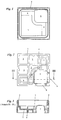
- the tub support shown is a shower tray support with a circumferential side wall 1, on the upper edge 2 of which the tub, not shown, is supported.
- the circumferential side wall 1 surrounds a floor 3 which is sunk in accordance with the depth of the shower tray.
- Crossing supporting ribs 4 are arranged below the bottom 3.
- a shaft 5 is left for the drain of the shower tray.
- closure elements 6 7 available.
- the closure elements 6 have springs on their sides, with which they are guided in corresponding grooves in the side wall 1.
- the contours of the assembly and inspection openings 7 and the corresponding contours of the closure elements 6 on the side facing the shaft 5 for the shower tray drain are smaller than on the outside of the side wall 1.
- the closure elements 6 are Not shown for the sake of clarity.
- two depressions 8 extending parallel to the side walls 1 are arranged in the base 3 for receiving a drain connection pipe, not shown.
- a shower tray is installed as follows. First, depending on the position of the building-side sewage pipe, the fitter cuts a piece from the side wall 1 or the floor 3 and, if necessary, from the support ribs 4 of the shower tray support for the closure to the building-side sewage pipe. Then he removes one of the two closure elements 6 on the side that is more convenient for him to assemble by pulling it downwards out of the side wall 1 of the shower tray support. The shower tray support is now set up on the floor, a drain connection pipe is connected to the building-side floor or wall connection and placed in the provided recess 8.
- the shower tray can be placed on the shower tray support and the drain of the shower tray can be connected through the mounting opening 7 to the shower tub-side end of the drain connection pipe.
- the fitter cuts off or breaks off the lateral springs of the closure element 6 and reinserts the closure element 6 into the assembly and inspection opening 7 from the outside.
- the side wall 1 of the shower tray support can now e.g. B. clad with tiles.
- the paneling in the area of the assembly and inspection opening 7 only has to be removed.
- the closure element 6 can then be removed to the front without destroying the shower tray support, so that repair work in the area of the shaft 5 is possible for the tub drain.
Landscapes
- Health & Medical Sciences (AREA)
- Public Health (AREA)
- Epidemiology (AREA)
- General Health & Medical Sciences (AREA)
- Sink And Installation For Waste Water (AREA)
- Domestic Plumbing Installations (AREA)
Abstract
Description
- Die Erfindung betrifft einen Wannenträger, insbesondere einen Badewannen- und Duschwannenträger, für die Aufnahme einer über einen Ablauf und ein Ablaufanschlußrohr an ein gebäudeseitiges Abwasserrohr anschließbaren Wanne, aus insbesondere geschäumten Kunststoff, mit einer umlaufenden Seitenwand, die einen der Wannentiefe entsprechend versenkten Boden umgibt, in dem zumindest ein Schacht für den Wannenablauf und wenigstens eine sich an den Schacht anschließende Vertiefung für die Aufnahme des Ablaufanschlußrohres angeordnet sind. Solche Wannenträger können selbstverständlich auch aus anderen Materialien als geschäumtem Kunststoff gefertigt sein.
- Derartige Wannenträger sind aus der DE 37 40 629 A1 bekannt, wobei die Seitenwand im Bereich des Schachtes für den Wannenablauf Sollbruchstellen aufweist, an denen Montage- und/oder Revisionsöffnungen vom Monteur herausgeschnitten oder herausgebrochen werden können. Auf diese Art und Weise eingebrachte Montage- und/oder Revisionsöffnungen sind nicht wiederverschließbar. Außerdem ist das Erstellen von Montage- und/oder Revisionsöffnungen durch Herausbrechen oder Herausschneiden von Material mühsam und zeitaufwendig.
- Aufgabe der Erfindung ist es, einen Wannenträger der eingangs beschriebenen Gattung anzugeben, dessen Seitenwand im Bereich des Schachtes für den Wannenablauf auf einfache Art und Weise zu Montage- und/oder Revisionszwecken zu öffnen und wieder verschließbar ist.
- Diese Aufgabe wird dadurch gelöst, daß die Seitenwand im Bereich des Schachtes für den Wannenablauf zumindest eine mit einem separaten Verschlußelement verschlossene Montage- und/oder Revisionsöffnung aufweist.
- Die Montage- und/oder Revisionsöffnung kann so zu Montage- und/oder Revisionszwecken geöffnet und nach Beendigung der Arbeiten mit dem Verschlußelement wieder verschlossen werden.
- Bei einer bevorzugten Ausführung der Erfindung ist das Verschlußelement von unten in die Seitenwand nach Art eines Schiebers hineingeschoben und so mit der Seitenwand formschlüssig verbunden. Von außen weist der Wannenträger dabei eine im wesentlichen einheitlich glatte Seitenwand auf. Auch wird die Seitenwand, solange sich das Verschlußelement noch in der Öffnung befindet, z. B. beim Transport etc., nicht unnötig geschwächt. Vor der Montage der Wanne entfernt der Monteur das Verschlußelement, indem er es einfach nach unten herauszieht.
- Vorzugsweise können Verschlußelement und Seitenwand mittels einer Feder-Nut-Verbindung miteinander verbunden sein. Eine derartige Verbindung gewährleistet einen guten Halt und eine sichere Führung des Verschlußelementes.
- Ferner können die Kontur der Montage- und/oder Revisionsöffnung und die korrespondierende Kontur des Verschlußelementes an der dem Schacht für den Wannenablauf zugewandten Seite kleiner als an der Außenseite der Seitenwand ausgebildet sein. Dadurch entsteht ein Anschlag für das Verschlußelement. Wird dieses nach den Montage- und/oder Revisionsarbeiten wieder in die Öffnung hineingesetzt, kann es nicht über die Seitenwand hinaus in das Innere des Wannenträgers hineingedrückt werden. Bei mittels Feder-Nut-Verbindung mit der Seitenwand verbundenen Verschlußelementen müssen dabei vor dem Wiedereinsetzen des Verschlußelementes in die Seitenwand die als Feder dienenden Bereiche des Verschlußelementes abgebrochen oder abgesägt werden.
- Im folgenden wird ein in der Zeichnung dargestelltes Ausführungsbeispiel der Erfindung erläutert; es zeigen:
- Fig. 1
- eine Draufsicht auf einen erfindungsgemäßen Wannenträger,
- Fig. 2
- eine Unteransicht unter den Gegenstand nach Fig. 1,
- Fig. 3
- einen Schnitt in Richtung III-III durch den Gegenstand nach Fig. 2.
- Bei dem dargestellten Wannenträger handelt es sich um einen Duschwannenträger mit einer umlaufenden Seitenwand 1, auf deren oberen Rand 2 sich die nicht dargestellte Wanne abstützt. Die umlaufende Seitenwand 1 umgibt einen Boden 3, der entsprechend der Tiefe der Duschwanne versenkt ist. Unterhalb des Bodens 3 sind sich kreuzende Stützrippen 4 angeordnet. An einer Ecke des Duschwannenträgers ist ein Schacht 5 für den Ablauf der Duschwanne ausgespart. Im Bereich des Schachtes 5 sind in der Seitenwand 1 mit Verschlußelementen 6 verschlossene Revisions- und Montageöffnungen 7 vorhanden. Die Verschlußelemente 6 weisen an ihren Seiten Federn auf, mit denen sie in korrespondierenden Nuten der Seitenwand 1 geführt sind. Wie man erkennen kann, sind die Konturen der Montage- und Revisionsöffnungen 7 sowie die korrespondierenden Konturen der Verschlußelemente 6 an der dem Schacht 5 für den Duschwannenablauf zugewandten Seite kleiner ausgebildet als an der Außenseite der Seitenwand 1. In Fig. 3 sind die Verschlußelemente 6 der Deutlichkeit halber nicht dargestellt. Vom Schacht 5 ausgehend sind in den Boden 3 zwei sich parallel zu den Seitenwänden 1 erstreckende Vertiefungen 8 zur Aufnahme eines nicht dargestellten Ablaufanschlußrohres angeordnet.
- Mit einem derartigen Duschwannenträger wird eine Duschwanne wie folgt montiert. Zunächst schneidet der Monteur je nach Lage des gebäudeseitigen Abwasserrohres von der Seitenwand 1 oder dem Boden 3 und gegebenenfalls aus den Stützrippen 4 des Duschwannenträgers ein Stück für den Abschluß an das gebäudeseitige Abwasserrohr heraus. Dann entfernt er eines der beiden Verschlußelemente 6 an der für ihn zur Montage günstigeren Seite, indem er es nach unten aus der Seitenwand 1 des Duschwannenträgers herauszieht. Der Duschwannenträger wird nun auf dem Boden aufgestellt, ein Ablaufanschlußrohr mit dem gebäudeseitigen Boden- oder Wandanschluß verbunden und in die vorgesehene Vertiefung 8 hineingelegt. Nun kann die Duschwanne auf den Duschwannenträger aufgesetzt und der Ablauf der Duschwanne durch die Montageöffnung 7 mit dem duschwannenseitigen Ende des Ablaufanschlußrohres verbunden werden. Im folgenden schneidet der Monteur die seitlichen Federn des Verschlußelementes 6 ab oder bricht diese ab und setzt das Verschlußelement 6 von außen wieder in die Montage- und Revisionsöffnung 7 hinein. Die Seitenwand 1 des Duschwannenträgers kann nun z. B. mit Fliesen verkleidet werden. Bei eventuellen Reparaturarbeiten braucht lediglich die Verkleidung im Bereich der Montage- und Revisionsöffnung 7 entfernt zu werden. Das Verschlußelement 6 kann dann ohne Zerstörungen an dem Duschwannenträger nach vorne herausgenommen werden, so daß Reparaturarbeiten im Bereich des Schachtes 5 für den Wannenablauf möglich sind.
Claims (4)
- Wannenträger, insbesondere Badewannen- und Duschwannenträger, für die Aufnahme einer über einen Ablauf und ein Ablaufanschlußrohr an ein gebäudeseitiges Abwasserrohr anschließbaren Wanne, aus insbesondere geschäumtem Kunststoff, mit einer umlaufenden Seitenwand, die einen der Wannentiefe entsprechend versenkten Boden umgibt, in dem zumindest ein Schacht für den Wannenablauf und wenigstens eine sich an den Schacht anschließende Vertiefung für die Aufnahme des Ablaufanschlußrohres angeordnet sind, dadurch gekennzeichnet, daß die Seitenwand (1) im Bereich des Schachtes (5) für den Wannenablauf zumindest eine mit einem separaten Verschlußelement (6) verschlossene Montage- und/oder Revisionsöffnung (7) aufweist.
- Wannenträger nach Anspruch 1, dadurch gekennzeichnet, daß das Verschlußelement (6) von unten in die Seitenwand (1) nach Art eines Schiebers hineingeschoben und so mit der Seitenwand (1) formschlüssig verbunden ist.
- Wannenträger nach Anspruch 2, dadurch gekennzeichnet, daß Verschlußelement (6) und Seitenwand (7) mittels einer Feder-Nut-Verbindung miteinander verbunden sind.
- Wannenträger nach einem der Ansprüche 1 bis 3, dadurch gekennzeichnet, daß die Kontur der Montage- und/oder Revisionsöffnung (7) und die korrespondierende Kontur des Verschlußelementes (6) an der dem Schacht (5) für den Wannenablauf zugewandten Seite kleiner als an der Außenseite der Seitenwand (1) sind.
Applications Claiming Priority (2)
| Application Number | Priority Date | Filing Date | Title |
|---|---|---|---|
| DE29602926U | 1996-02-12 | ||
| DE29602386U DE29602386U1 (de) | 1996-02-12 | 1996-02-12 | Wannenträger, insbesondere Badewannen- und Duschwannenträger |
Publications (2)
| Publication Number | Publication Date |
|---|---|
| EP0788755A1 true EP0788755A1 (de) | 1997-08-13 |
| EP0788755B1 EP0788755B1 (de) | 2000-03-01 |
Family
ID=8019327
Family Applications (1)
| Application Number | Title | Priority Date | Filing Date |
|---|---|---|---|
| EP97101846A Expired - Lifetime EP0788755B1 (de) | 1996-02-12 | 1997-02-06 | Wannenträger, insbesondere Badewannen- und Duschwannenträger |
Country Status (3)
| Country | Link |
|---|---|
| EP (1) | EP0788755B1 (de) |
| DE (2) | DE29602386U1 (de) |
| PL (1) | PL182733B1 (de) |
Cited By (3)
| Publication number | Priority date | Publication date | Assignee | Title |
|---|---|---|---|---|
| EP1210897A3 (de) * | 2000-12-02 | 2003-07-02 | Michael Dr. Gerloff | Trägerkörper für ein Duschtasse |
| EP2245973A3 (de) * | 2009-04-24 | 2014-10-22 | Urs Gassmann | Unterbausystem für Duschwannen und Duschböden |
| EP2591709B1 (de) * | 2011-11-10 | 2018-03-21 | poresta systems GmbH | Duschbodenelement und Einbauset für ein Duschbodenelement |
Families Citing this family (2)
| Publication number | Priority date | Publication date | Assignee | Title |
|---|---|---|---|---|
| DE19704113C2 (de) * | 1997-02-05 | 1999-07-29 | Kunststofftechnik Schedel Gmbh | Duschwannenträger |
| DE102004049130A1 (de) * | 2004-10-07 | 2006-04-13 | Artweger Gmbh & Co. | Duschwanne mit auf einem höhenverstellbaren Duschwannenträger aufsetzbarer Duschwannenschale |
Citations (5)
| Publication number | Priority date | Publication date | Assignee | Title |
|---|---|---|---|---|
| DE8507760U1 (de) * | 1985-03-15 | 1985-05-30 | Menden, Leo, 5342 Rheinbreitbach | Bade- oder Brausewannenträger |
| DE8703968U1 (de) * | 1987-03-17 | 1987-04-23 | Correcta GmbH, 3590 Bad Wildungen | Armaturenblock einer Wanneneinfassung aus Kunststoffschaum |
| DE8715872U1 (de) * | 1987-12-01 | 1988-01-14 | Correcta GmbH, 3590 Bad Wildungen | Wannenträger, insbesondere Duschwannenträger |
| EP0261521A1 (de) * | 1986-09-24 | 1988-03-30 | Correcta GmbH | Universal-Wannentraeger |
| DE9415500U1 (de) * | 1994-08-15 | 1994-11-17 | Correcta GmbH, 34537 Bad Wildungen | Wannenträger |
-
1996
- 1996-02-12 DE DE29602386U patent/DE29602386U1/de not_active Expired - Lifetime
-
1997
- 1997-02-06 DE DE59701157T patent/DE59701157D1/de not_active Expired - Fee Related
- 1997-02-06 EP EP97101846A patent/EP0788755B1/de not_active Expired - Lifetime
- 1997-02-10 PL PL97318410A patent/PL182733B1/pl not_active IP Right Cessation
Patent Citations (5)
| Publication number | Priority date | Publication date | Assignee | Title |
|---|---|---|---|---|
| DE8507760U1 (de) * | 1985-03-15 | 1985-05-30 | Menden, Leo, 5342 Rheinbreitbach | Bade- oder Brausewannenträger |
| EP0261521A1 (de) * | 1986-09-24 | 1988-03-30 | Correcta GmbH | Universal-Wannentraeger |
| DE8703968U1 (de) * | 1987-03-17 | 1987-04-23 | Correcta GmbH, 3590 Bad Wildungen | Armaturenblock einer Wanneneinfassung aus Kunststoffschaum |
| DE8715872U1 (de) * | 1987-12-01 | 1988-01-14 | Correcta GmbH, 3590 Bad Wildungen | Wannenträger, insbesondere Duschwannenträger |
| DE9415500U1 (de) * | 1994-08-15 | 1994-11-17 | Correcta GmbH, 34537 Bad Wildungen | Wannenträger |
Cited By (3)
| Publication number | Priority date | Publication date | Assignee | Title |
|---|---|---|---|---|
| EP1210897A3 (de) * | 2000-12-02 | 2003-07-02 | Michael Dr. Gerloff | Trägerkörper für ein Duschtasse |
| EP2245973A3 (de) * | 2009-04-24 | 2014-10-22 | Urs Gassmann | Unterbausystem für Duschwannen und Duschböden |
| EP2591709B1 (de) * | 2011-11-10 | 2018-03-21 | poresta systems GmbH | Duschbodenelement und Einbauset für ein Duschbodenelement |
Also Published As
| Publication number | Publication date |
|---|---|
| PL318410A1 (en) | 1997-08-18 |
| DE59701157D1 (de) | 2000-04-06 |
| DE29602386U1 (de) | 1996-04-25 |
| EP0788755B1 (de) | 2000-03-01 |
| PL182733B1 (pl) | 2002-02-28 |
Similar Documents
| Publication | Publication Date | Title |
|---|---|---|
| EP3854951B1 (de) | Bodenablauf | |
| EP1782721B1 (de) | Duschtassenelement mit einer Ablaufrinne | |
| EP3705655A1 (de) | Bodenablauf zum abführen von wasser von einem begehbaren boden in eine abwasserleitung | |
| EP2808458B1 (de) | Wasserablaufvorrichtung für eine Dusche und Duschbodenelement | |
| EP2756137B1 (de) | Ablaufrinne für eine bodengleiche dusche | |
| EP0788755B1 (de) | Wannenträger, insbesondere Badewannen- und Duschwannenträger | |
| DE20008180U1 (de) | Duschwanne | |
| EP2353442B1 (de) | Ausschnittsumrandung für einen Schubkasten | |
| DE102012106924A1 (de) | Ablaufanordnung | |
| EP2048292A2 (de) | Entwässerungsrinne | |
| DE102017103783A1 (de) | Vorrichtung für einen im Boden eines Raumes angeordneten Bodenablauf | |
| DE69806370T2 (de) | Viereckige bzw. rechteckige strasseneinrichtung mit einem stützrahmen und einem abdeckelement | |
| DE102017111331B4 (de) | Entwässerungsrinne, Verfahren zur Herstellung | |
| DE29503911U1 (de) | Bausatz für einen Einlauf- oder Sinkkasten für eine Entwässerungsrinne | |
| DE2500337B2 (de) | Spüle für Haushalte | |
| DE202011004001U1 (de) | Ablaufanordnung | |
| EP0071187B1 (de) | Haltevorrichtung für Schalbretter bei Deckenbetonierungen od. dgl. | |
| DE3740629C2 (de) | Wannenträger, insbesondere Duschwannenträger | |
| DE10260693A1 (de) | Reinigungs- und Spüleinsatz für Rinnensysteme | |
| EP3375944B1 (de) | Entwässerungsrinne, verfahren zur herstellung und verfahren zum einbau | |
| DE7634746U1 (de) | Gully- oder bodenabflussfang | |
| EP0673617B1 (de) | Wannenträger | |
| EP0385080A1 (de) | Vorrichtung zum Abstützen und Verkleiden einer Badewanne od.dgl. | |
| DE4230083C2 (de) | Wannenträger | |
| CH688722A5 (de) | Formelement zur Erzeugung einer Aussparung in einem Betonbauteil. |
Legal Events
| Date | Code | Title | Description |
|---|---|---|---|
| PUAI | Public reference made under article 153(3) epc to a published international application that has entered the european phase |
Free format text: ORIGINAL CODE: 0009012 |
|
| AK | Designated contracting states |
Kind code of ref document: A1 Designated state(s): BE DE FR NL |
|
| 17P | Request for examination filed |
Effective date: 19971002 |
|
| RAP1 | Party data changed (applicant data changed or rights of an application transferred) |
Owner name: ALPHA-SAN GMBH SANITAERTECHNIK |
|
| 17Q | First examination report despatched |
Effective date: 19990401 |
|
| GRAG | Despatch of communication of intention to grant |
Free format text: ORIGINAL CODE: EPIDOS AGRA |
|
| GRAG | Despatch of communication of intention to grant |
Free format text: ORIGINAL CODE: EPIDOS AGRA |
|
| GRAH | Despatch of communication of intention to grant a patent |
Free format text: ORIGINAL CODE: EPIDOS IGRA |
|
| GRAH | Despatch of communication of intention to grant a patent |
Free format text: ORIGINAL CODE: EPIDOS IGRA |
|
| GRAA | (expected) grant |
Free format text: ORIGINAL CODE: 0009210 |
|
| AK | Designated contracting states |
Kind code of ref document: B1 Designated state(s): BE DE FR NL |
|
| REF | Corresponds to: |
Ref document number: 59701157 Country of ref document: DE Date of ref document: 20000406 |
|
| ET | Fr: translation filed | ||
| PLBE | No opposition filed within time limit |
Free format text: ORIGINAL CODE: 0009261 |
|
| STAA | Information on the status of an ep patent application or granted ep patent |
Free format text: STATUS: NO OPPOSITION FILED WITHIN TIME LIMIT |
|
| 26N | No opposition filed | ||
| PGFP | Annual fee paid to national office [announced via postgrant information from national office to epo] |
Ref country code: NL Payment date: 20040216 Year of fee payment: 8 |
|
| PGFP | Annual fee paid to national office [announced via postgrant information from national office to epo] |
Ref country code: FR Payment date: 20040217 Year of fee payment: 8 |
|
| PG25 | Lapsed in a contracting state [announced via postgrant information from national office to epo] |
Ref country code: NL Free format text: LAPSE BECAUSE OF NON-PAYMENT OF DUE FEES Effective date: 20050901 |
|
| PG25 | Lapsed in a contracting state [announced via postgrant information from national office to epo] |
Ref country code: FR Free format text: LAPSE BECAUSE OF NON-PAYMENT OF DUE FEES Effective date: 20051031 |
|
| NLV4 | Nl: lapsed or anulled due to non-payment of the annual fee |
Effective date: 20050901 |
|
| REG | Reference to a national code |
Ref country code: FR Ref legal event code: ST Effective date: 20051031 |
|
| PGFP | Annual fee paid to national office [announced via postgrant information from national office to epo] |
Ref country code: DE Payment date: 20070220 Year of fee payment: 11 |
|
| PGFP | Annual fee paid to national office [announced via postgrant information from national office to epo] |
Ref country code: BE Payment date: 20070301 Year of fee payment: 11 |
|
| BERE | Be: lapsed |
Owner name: *ALPHA-SAN G.M.B.H. SANITARTECHNIK Effective date: 20080228 |
|
| PG25 | Lapsed in a contracting state [announced via postgrant information from national office to epo] |
Ref country code: DE Free format text: LAPSE BECAUSE OF NON-PAYMENT OF DUE FEES Effective date: 20080902 |
|
| PG25 | Lapsed in a contracting state [announced via postgrant information from national office to epo] |
Ref country code: BE Free format text: LAPSE BECAUSE OF NON-PAYMENT OF DUE FEES Effective date: 20080228 |