EP0786594A2 - Zusammensetzung einer Francis-Turbine - Google Patents
Zusammensetzung einer Francis-Turbine Download PDFInfo
- Publication number
- EP0786594A2 EP0786594A2 EP97100961A EP97100961A EP0786594A2 EP 0786594 A2 EP0786594 A2 EP 0786594A2 EP 97100961 A EP97100961 A EP 97100961A EP 97100961 A EP97100961 A EP 97100961A EP 0786594 A2 EP0786594 A2 EP 0786594A2
- Authority
- EP
- European Patent Office
- Prior art keywords
- ring
- hydraulic machine
- head cover
- guide vane
- runner
- Prior art date
- Legal status (The legal status is an assumption and is not a legal conclusion. Google has not performed a legal analysis and makes no representation as to the accuracy of the status listed.)
- Granted
Links
Images



Classifications
-
- F—MECHANICAL ENGINEERING; LIGHTING; HEATING; WEAPONS; BLASTING
- F03—MACHINES OR ENGINES FOR LIQUIDS; WIND, SPRING, OR WEIGHT MOTORS; PRODUCING MECHANICAL POWER OR A REACTIVE PROPULSIVE THRUST, NOT OTHERWISE PROVIDED FOR
- F03B—MACHINES OR ENGINES FOR LIQUIDS
- F03B3/00—Machines or engines of reaction type; Parts or details peculiar thereto
- F03B3/02—Machines or engines of reaction type; Parts or details peculiar thereto with radial flow at high-pressure side and axial flow at low-pressure side of rotors, e.g. Francis turbines
-
- F—MECHANICAL ENGINEERING; LIGHTING; HEATING; WEAPONS; BLASTING
- F04—POSITIVE - DISPLACEMENT MACHINES FOR LIQUIDS; PUMPS FOR LIQUIDS OR ELASTIC FLUIDS
- F04D—NON-POSITIVE-DISPLACEMENT PUMPS
- F04D1/00—Radial-flow pumps, e.g. centrifugal pumps; Helico-centrifugal pumps
- F04D1/02—Radial-flow pumps, e.g. centrifugal pumps; Helico-centrifugal pumps having non-centrifugal stages, e.g. centripetal
-
- F—MECHANICAL ENGINEERING; LIGHTING; HEATING; WEAPONS; BLASTING
- F03—MACHINES OR ENGINES FOR LIQUIDS; WIND, SPRING, OR WEIGHT MOTORS; PRODUCING MECHANICAL POWER OR A REACTIVE PROPULSIVE THRUST, NOT OTHERWISE PROVIDED FOR
- F03B—MACHINES OR ENGINES FOR LIQUIDS
- F03B3/00—Machines or engines of reaction type; Parts or details peculiar thereto
- F03B3/12—Blades; Blade-carrying rotors
- F03B3/128—Mounting, demounting
-
- Y—GENERAL TAGGING OF NEW TECHNOLOGICAL DEVELOPMENTS; GENERAL TAGGING OF CROSS-SECTIONAL TECHNOLOGIES SPANNING OVER SEVERAL SECTIONS OF THE IPC; TECHNICAL SUBJECTS COVERED BY FORMER USPC CROSS-REFERENCE ART COLLECTIONS [XRACs] AND DIGESTS
- Y02—TECHNOLOGIES OR APPLICATIONS FOR MITIGATION OR ADAPTATION AGAINST CLIMATE CHANGE
- Y02E—REDUCTION OF GREENHOUSE GAS [GHG] EMISSIONS, RELATED TO ENERGY GENERATION, TRANSMISSION OR DISTRIBUTION
- Y02E10/00—Energy generation through renewable energy sources
- Y02E10/20—Hydro energy
Definitions
- the present invention relates to a hydraulic machine such as a hydraulic turbine, a pump and a reversible pump-turbine. More specifically, the invention relates to a hydraulic machine which can be easily disassembled and assembled.
- a typical hydraulic machine such as a hydraulic turbine and a pump, is installed in a double-flooring type building or a barrel type building.
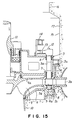
- Fig. 15 shows a conventional hydraulic machine installed in a barrel type building.
- This hydraulic machine comprises a spiral case 1 connected to a steel pipe which introduces water from an upper pond (not shown), a stay vane 2a arranged on the inner periphery of the spiral case 1, and a stay ring 2 which clamps the stay vane 2a from the upper and lower sides to form a passage.
- the stay ring 2 has an upper flange 2b and a lower flange 2b.
- a head cover 3 having a head-cover flange portion 3a is mounted by connecting the head-cover flange portion 3a to the upper flange 2b by means of bolts.
- a bottom cover 4 having a bottom-ring flange portion 4a is mounted by connecting the bottom-ring flange portion 4a to the lower flange 2c by means of bolts.
- a guide vane 5 is arranged so as to form a circular cascade.
- the guide vane 5 has an upper spindle 5a and a lower spindle 5b.
- the upper spindle 5a of the guide vane 5 is rotatably supported on an upper guide vane bushing 6 and an intermediate bearing 7, which are provided on the head cover 3.
- the lower spindle 5b is rotatably supported on a lower bearing 8 provided on the bottom cover 4.
- Water flow-regulated by the guide vane 5 flows into a runner 9, and water flowing out of the runner 9 passes through an upper draft tube 10 to be discharged from a draft tube liner to a tailrace.
- the runner 9 is connected to the lower end portion of a turbine main shaft 11. Rotational torque of the runner 9 is transmitted to a generator via the turbine main shaft 11 to generate electricity.
- the head cover 3 is formed with an outer-periphery seal on the side of a runner crown 9a.
- the head cover 3 is also provided with a guide vane arm 12, a guide vane ring 13 and a operating ring 14.
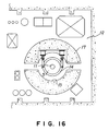
- a lower pit liner 15 and an upper pit liner 16 are provided to form a pit of the hydraulic turbine. As shown in Fig. 16, each of the pit liners 15 and 16 is provided with a concreted turbine barrel 17.
- This turbine barrel 17 is designed to sufficiently support thereon the weights of generator stationary and rotary portions loaded on the lower pit liner 15, the hydraulic thrust weight when being driven, and so forth.
- the size of a turbine room 19 is determined in view of the size of the turbine barrel 17 and the maintenance space for auxiliary machinery provided in the turbine room 19.
- a generator lower bearing bracket is provided with a thrust bearing and a lower guide bearing.
- it is required to decrease the diameter of the generator lower bearing bracket.
- the inner diameter of the upper pit liner 16, on which the lower bearing bracket is mounted must be decreased.
- the head cover 3 which is a large structure of the hydraulic machine and which is required to be disassembled for maintenance, has a four-piece structure which can be divided into four pieces.
- the inner diameter of the upper pit liner 16 is determined to be a necessary and minimum size in which each divided pieces can be lifted. For that reason, the inner diameter of the upper pit liner 16 is less than the inner diameter of the lower pit liner 15.
- the conventional head cover 3 has a four-piece structure. Therefore, in order to assemble the head cover 3, four pieces must be combined with each other on the guide vane 5 in a complicated process to fasten joint portions by means of bolts, and then, the fastened four pieces must be mounted on the upper spindle 5a of the guide vane 5.
- the head cover 3 must be assembled at a high level above the guide vane 5 and within a narrow pit while the heavy equipment is lowered through the narrow upper pit liner 16 by means of a crane. Therefore, the assembly work must be carefully performed by skilled persons for several days.
- the head cover 3 In a field assembly of a hydraulic machine, in order to align the stationary parts, the head cover 3 is first temporarily assembled to perform the alignment. After the temporary assembly and alignment are completed, the head cover 3 is disassembled to be lifted. Thereafter, the runner 9 and the turbine main shaft 11 are introduced, and then, the head cover 3 is assembled again to install the hydraulic machine on the site. For that reason, it takes about two weeks to perform the assembly, disassembly and re-assembly processes of the head cover 3. However, in recent years, in the field installation work, it is required to shorten the processes to early increase the quantity of power supply, so that it is greatly desired to shorten the assembly operation of the head cover 3.
- the outer diameter of the turbine barrel 17 is derived by adding, to the inner diameter of the lower pit liner 15, a necessary thickness of concrete, which can bear the weights of stationary parts and rotary portions of the generator, and the water thrust load produced when the hydraulic machine is actuated.
- the inner diameter of the lower pit liner 15 is greater than the outer diameter of the head cover 3 by a work space required for tools which fasten head-cover mounting bolts. Therefore, the outer diameter of the turbine barrel is increased, so that the maintenance space for auxiliary machinery on the turbine room floor is insufficient.
- the floor size may be increased to increase the construction cost.
- the head cover 3 since the head cover 3 must be disassembled and assembled after it is temporarily arranged on the guide vane 5, it is required to secure a space in a vertical direction for arranging therein the divided pieces of the head cover 3. Therefore, the height of the lower pit liner 15 is so defined as to secure the space.
- the installation position of the generator is determined on the basis of the height of the lower pit liner 15. Therefore, even if the height of the generator is decreased and the height of the building is also decreased, it is not possible to lower the installation position of the generator unless the method for assembling the head cover 3 is changed, so that it is not possible to decrease the construction period and cost.
- the installation position of the generator is a high position, the turbine main shaft 11 and the generator shaft are long, so that the critical speed is decreased. Therefore, it is required to enhance the rigidities of the shafts, e.g., by increasing the diameters of the shafts.
- the runner 9 and the guide vane 5 are carried out for repair, it is required to disassemble the generator to lift the disassembled generator. Therefore, it is also required to disassemble a set of parts mounted on the head cover 3, so that the term of repairing work is remarkably increased.
- the repairing interval is decreased due to cavitation damage and sedimentary friction, so that it is required to decrease the term of repairing work in order to improve the availability.
- a hydraulic machine installed in a barrel type building, comprising: a stay ring having a stay vane; a head cover and a bottom ring, which are arranged on an inner-periphery side of the stay ring; a guide vane arranged in a passage between the head cover and the bottom ring, the guide vane having an upper spindle and a lower spindle; a runner for converting energy of water flow-regulated by the guide vane; and a turbine main shaft rotating with the runner, wherein the stay ring has a bearing for supporting thereon the upper spindle, and the bottom ring has a bearing for supporting thereon the lower spindle.
- the stay ring may be formed with a runner-crown side outer-seal on the inner periphery thereof.
- the pitch circle of bolts for mounting the head cover may be arranged inside of the pitch circle of the guide vane, and the head cover may be connected to the stay ring by means of bolts.
- the head cover may comprise a bottom plate for defining a runner back-pressure chamber, an upper ring for supporting thereon a guide ring and a bearing stand, and a tapered cylindrical side plate for connecting the bottom plate to the upper ring, wherein a guide vane arm is provided on the bearing for supporting thereon the upper spindle.
- a hydraulic machine installed in a barrel of a building, comprising: a stay ring having a stay vane; a head cover and a bottom ring, which are arranged on an inner-periphery side of the stay ring; a guide vane arranged in a passage between the head cover and the bottom ring; a runner for converting energy of water flow-regulated by the guide vane; and a turbine main shaft rotating with the runner, wherein an intermediate shaft having a predetermined length is detachably mounted on the turbine main shaft, and wherein a carrying passage, which extends toward a hatch for carrying the hydraulic machine in and out, is formed in the periphery of the barrel.
- the hatch may also serve to carry an inlet vale in and out. Thus, it is not required to provide an exclusive hatch for the hydraulic machine, so that it is possible to the building space.
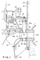
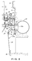
- FIGs. 1 and 2 show the first preferred embodiment of a hydraulic machine according to the present invention.
- This hydraulic machine is installed in a barrel type building.
- the hydraulic machine comprises a spiral type spiral case 21 connected to a steel pipe which introduces water from an upper pond (not shown), and stay ring 22, which is arranged on the inner periphery of the spiral case 21 and which clamps a stay vane 21a from the upper and lower sides to form a passage.
- a head cover 23 and a bottom cover 24 are arranged on the upper and lower sides so as to face each other.
- the head cover 23 and the bottom cover 24 are connected to the stay ring 22 by means of bolts.
- a guide vane 25 is arranged in the passage inside of the stay vane 22a and between the head cover 23 and the bottom cover 24.
- the guide vane 25 has an upper spindle 25a and a lower spindle 25b.
- the upper spindle 25a of the guide vane 25 is rotatably supported on an upper guide vane bushing 26 and an intermediate bearing 27, which are provided on the stay ring 22.
- the lower spindle 25b of the guide vane 25 is rotatably supported on a lower bearing 28 provided on the bottom cover 24.
- runner 29 As can be seen from Figs. 1 and 2, water flow-regulated by the guide vane 25 flows into a runner 29, and then, water flowing out of the runner 29 passes through the upper draft tube 30, which is detachably connected to the bottom of the bottom cover 24, to be discharged from a draft tube liner 18 to a tailrace.
- the runner 29 is connected to the lower end portion of a turbine main shaft 31, so that rotational torque of the runner 29 is transmitted to a generator via the turbine main shaft 31 to generate electricity.
- the runner 29 has a runner crown 29a. The outer peripheral portion of the runner crown 29a faces the inner peripheral portion of the stay ring 22.
- the head cover 23 comprises a bottom plate 23a which defines a runner back-pressure chamber, an upper ring 23b which supports thereon a operating ring 34 and a bearing stand 38, a tapered cylindrical side plate 23c which connects the bottom plate 23a to the upper ring 23b.
- the head cover 23 is formed as an integral structure.
- the pitch circle of mounting bolts therefor is set to be inside of the pitch circle of the guide vane 25.
- the inner diameter of a lower pit liner 35 can be decreased so that the lower pit liner 35 is arranged in the vicinity of a guide vane lever 32.
- the guide vane lever 32 is mounted on the upper guide vane bushing 26 arranged at the upper end of the stay ring 22.
- the guide vane lever 32 is connected to the operating ring 34 via a guide vane link 33.
- the lower pit liner 35 and an upper pit liner 36 are arranged to form a pit of the hydraulic turbine.
- a concreted turbine barrel 37 is provided on the outer-periphery side of these pit liners 35 and 36. This turbine barrel 37 is designed to sufficiently support thereon the weights of generator stationary and rotary portions loaded on the lower pit liner 35, the hydraulic thrust weight when being driven, and so forth. Operation of the preferred embodiment of a hydraulic machine according to the present invention will be described below.
- the upper draft tube 30 is first removed and the bottom cover 24 is then removed as shown in Fig. 3. These removed parts are conveyed to the outside through a draft check passage. Then, a runner inspection frame 39 is installed on the draft tube liner 18. Thereafter, the runner 29 is removed from the turbine shaft 31 by removing coupling bolts, and the removed runner 29 is lowered to be put on the runner inspection frame 39. In this condition, the runner 29 is repaired.
- Figs. 4(a) and 4(b) show the comparison between the heights of a conventional hydraulic machine using a divided type head cover 3, and a hydraulic machine using an integral head cover 23 according to the present invention.
- a work space 40 is required.
- the height of the lower pit liner 15 is determined.
- a lower-bracket installed plate 41 is determined by adding the thickness of concrete, which is necessary for the foundation of a generator lower bracket, to the height of the lower pit liner 15.
- a generator floor plane 42 is determined.
- the head cover 23 has a compact and integral structure so that it can be directly lifted through the upper pit liner 36.
- the stay ring 22 is provided with the upper guide vane bushing 26 and the middle guide vane bushing 27, which support thereon the upper spindle 25a of the guide vane 25, it is possible to remove the guide vane 25 on the bottom side to repair the guide vane 25 after removing the bottom cover 24 and the upper draft tube 30.
- the runner 29 can be removed on the bottom side to be repaired in the draft check passage, it is not required to disassemble the generator when the runner 29 is repaired.
- the pitch circle of the bolts for mounting the head cover 23 is arranged inside of the pitch circle of the guide vane 25, it is possible to make the head cover 23 compact to directly lift the head cover 23 through the upper pit liner 36 if it is formed as an integral structure. Therefore, it is possible to remarkably decrease the term of field installation work, and it is also possible to decrease the manufacturing period of time in a maker.
- the outer diameter of the head cover 23 is decreased, hydraulic pressure applied to the lower portion of the head cover 23 is applied inside of the runner outer-periphery seal, so that it is possible to decrease the pressure and to decrease the quantity of flexure of the head cover 23 due to hydraulic pressure.
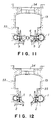
- FIGs. 5 and 6 show the second preferred embodiment of a hydraulic machine according to the present invention.
- an intermediate shaft 51 is detachably mounted on the turbine shaft 11 of the conventional hydraulic machine shown in Fig. 15, and a carrying passage 53 extending toward a hatch 52 for introducing the hydraulic machine is formed in the periphery of the lower pit liner 15, so that the disassembled parts of the hydraulic machine can be carried in and out without disassembling the generator 54.
- the intermediate shaft 51 of a predetermined length is detachably mounted on the upper end portion of the turbine shaft 11, and the carrying passage 53 extending toward the hatch 52 for carrying the hydraulic machine is formed in the periphery of the lower pit liner 15.
- a carrying rail 55 is embedded in the lower pit liner 15 and the carrying passage 53.
- the disassembled parts of the hydraulic machine are treated using a truck 56 and a lifting unit 57, which travel along the carrying rail 55, so that the disassembled parts of the hydraulic machine can be carried without disassembling the generator 54.
- reference number 58 denotes a hatch cover.
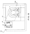
- FIGs. 13 and 14 show the third preferred embodiment of a hydraulic machine according to the present invention.
- a hatch 62 and a carrying passage 63 are substituted for the hatch 52 and the carrying passage 53 in the second preferred embodiment, respectively. That is, as shown in Figs. 13 and 14, the carrying passage 63 extending toward the hatch 62 for carrying an inlet valve 60 is formed in the periphery of the lower pit liner 15.
- the disassembled parts of the hydraulic machine are conveyed to the hatch 62 through the carrying passage 63, and then, carried to through the hatch 62.
- reference number 68 denotes a hatch cover.
Landscapes
- Engineering & Computer Science (AREA)
- Mechanical Engineering (AREA)
- General Engineering & Computer Science (AREA)
- Chemical & Material Sciences (AREA)
- Combustion & Propulsion (AREA)
- Hydraulic Turbines (AREA)
Applications Claiming Priority (3)
| Application Number | Priority Date | Filing Date | Title |
|---|---|---|---|
| JP946696 | 1996-01-23 | ||
| JP9466/96 | 1996-01-23 | ||
| JP00946696A JP3798457B2 (ja) | 1996-01-23 | 1996-01-23 | 水力機械 |
Publications (4)
| Publication Number | Publication Date |
|---|---|
| EP0786594A2 true EP0786594A2 (de) | 1997-07-30 |
| EP0786594A3 EP0786594A3 (de) | 2000-12-20 |
| EP0786594B1 EP0786594B1 (de) | 2002-09-04 |
| EP0786594B2 EP0786594B2 (de) | 2005-03-02 |
Family
ID=11721061
Family Applications (1)
| Application Number | Title | Priority Date | Filing Date |
|---|---|---|---|
| EP97100961A Expired - Lifetime EP0786594B2 (de) | 1996-01-23 | 1997-01-22 | Zusammensetzung einer Francis-Turbine |
Country Status (6)
| Country | Link |
|---|---|
| US (1) | US5871331A (de) |
| EP (1) | EP0786594B2 (de) |
| JP (1) | JP3798457B2 (de) |
| KR (1) | KR100229199B1 (de) |
| CN (1) | CN1100205C (de) |
| DE (1) | DE69715058T3 (de) |
Cited By (2)
| Publication number | Priority date | Publication date | Assignee | Title |
|---|---|---|---|---|
| WO2003031810A1 (en) * | 2001-10-11 | 2003-04-17 | Alstom Canada Inc. | Hydraulic turbine with increased power capacities |
| RU2275525C1 (ru) * | 2005-06-22 | 2006-04-27 | Общество с ограниченной ответственностью "ГИДРОЭН" | Способ восстановления работоспособности гидроагрегата |
Families Citing this family (9)
| Publication number | Priority date | Publication date | Assignee | Title |
|---|---|---|---|---|
| US6918744B2 (en) * | 2002-08-21 | 2005-07-19 | Alexander Gokhman | Hydraulic turbine and exit stay apparatus therefor |
| JP2013096245A (ja) * | 2011-10-28 | 2013-05-20 | Toshiba Corp | 水力機械およびその分解方法 |
| JP2013170571A (ja) * | 2012-02-23 | 2013-09-02 | Toshiba Corp | 軸流水車 |
| KR101389054B1 (ko) * | 2012-12-10 | 2014-04-28 | 목포대학교산학협력단 | 일체형 케이싱 시스템을 구비한 수력기계 |
| JP6121239B2 (ja) * | 2013-05-20 | 2017-04-26 | 株式会社日立製作所 | プルアウト型立軸ポンプ |
| CN108526882B (zh) * | 2018-06-08 | 2023-09-12 | 天津市天发重型水电设备制造有限公司 | 一种立式机组使用的多功能圆柱式导水机构装配工装 |
| CN113864098B (zh) * | 2021-08-26 | 2023-12-19 | 长江勘测规划设计研究有限责任公司 | 立轴双级混流机组转轮中拆和下拆检修方法 |
| CN114320706B (zh) * | 2021-12-06 | 2023-10-27 | 长江勘测规划设计研究有限责任公司 | 立式两级混流水轮机二级流道的复合轴系支撑方法 |
| CN114293522B (zh) * | 2021-12-31 | 2023-10-31 | 中铁二十局集团第六工程有限公司 | 水轮发电机组的管型座安装方法及管型座 |
Family Cites Families (20)
| Publication number | Priority date | Publication date | Assignee | Title |
|---|---|---|---|---|
| DE274954C (de) * | ||||
| US1449006A (en) * | 1922-03-01 | 1923-03-20 | Pelton Water Wheel Co | Vertical turbine construction |
| US1516095A (en) * | 1922-06-13 | 1924-11-18 | Worthington Pump & Mach Corp | Hydraulic turbine plant |
| DE876230C (de) * | 1949-03-20 | 1953-05-11 | Voith Gmbh J M | Turbinendeckel |
| DE841130C (de) * | 1949-04-26 | 1952-06-13 | Escher Wyss Maschinenfabrik G | Wasserturbine oder Pumpe mit stehender Welle und hydraulisch verstellbaren Laufradschaufeln |
| FR1263353A (fr) * | 1960-04-28 | 1961-06-09 | Electricite De France | Usine hydro-électrique et son procédé de réalisation |
| CA891846A (en) * | 1968-12-13 | 1972-02-01 | Dominion Engineering Works | Hydraulic machine structure |
| JPS4937034A (de) * | 1972-08-21 | 1974-04-06 | ||
| US3923418A (en) * | 1974-12-23 | 1975-12-02 | Allis Chalmers | Hydraulic turbine installation and method of assembling the turbine headcover therein |
| US4224526A (en) * | 1978-02-06 | 1980-09-23 | A. D. Margison Management Ltd. | Prefabricated hydro-electric generating station |
| US4406577A (en) * | 1979-10-29 | 1983-09-27 | Tokyo Shibaura Denki Kabushiki Kaisha | Multi-stage hydraulic machine and a method of operating same |
| EP0061269B1 (de) * | 1981-03-23 | 1988-05-18 | Kabushiki Kaisha Toshiba | Mehrstufige hydraulische Rotationsmaschine |
| JPS58144668A (ja) * | 1982-02-24 | 1983-08-29 | Hitachi Ltd | 回転水力機械のランナ分解および組立方法ならびにその装置 |
| JPS59105973A (ja) * | 1982-12-10 | 1984-06-19 | Hitachi Ltd | 水力機械の案内羽根操作装置 |
| DE3512641A1 (de) * | 1984-04-12 | 1985-10-24 | Kabushiki Kaisha Toshiba, Kawasaki, Kanagawa | Mehrstufige, hydraulische maschine |
| DE3440635A1 (de) * | 1984-11-07 | 1986-05-22 | J.M. Voith Gmbh, 7920 Heidenheim | Verfahren zum abdichten des deckelseitigen gehaeuses von hydraulischen maschinen sowie maschine zur durchfuehrung des verfahrens |
| JPS61149580A (ja) * | 1984-12-22 | 1986-07-08 | Toshiba Corp | 水力機械の分解方法 |
| JPS61226570A (ja) * | 1985-03-29 | 1986-10-08 | Toshiba Corp | 水力機械の回転部分解方法 |
| FR2593246B1 (fr) * | 1986-01-20 | 1988-03-25 | Bergeron Sa | Procede pour la realisation des interfaces entre les elements en beton et les elements mecaniques d'une pompe a volute en beton et pompe obtenue par ce procede |
| DE69303085T3 (de) * | 1992-03-19 | 2003-06-12 | Hitachi, Ltd. | Wasserkraftmaschine |
-
1996
- 1996-01-23 JP JP00946696A patent/JP3798457B2/ja not_active Expired - Lifetime
-
1997
- 1997-01-21 KR KR1019970001653A patent/KR100229199B1/ko not_active Expired - Lifetime
- 1997-01-22 DE DE69715058T patent/DE69715058T3/de not_active Expired - Lifetime
- 1997-01-22 EP EP97100961A patent/EP0786594B2/de not_active Expired - Lifetime
- 1997-01-23 US US08/786,935 patent/US5871331A/en not_active Expired - Lifetime
- 1997-01-23 CN CN97100422A patent/CN1100205C/zh not_active Expired - Lifetime
Non-Patent Citations (1)
| Title |
|---|
| None |
Cited By (3)
| Publication number | Priority date | Publication date | Assignee | Title |
|---|---|---|---|---|
| WO2003031810A1 (en) * | 2001-10-11 | 2003-04-17 | Alstom Canada Inc. | Hydraulic turbine with increased power capacities |
| US6926494B2 (en) | 2001-10-11 | 2005-08-09 | Alstom Canada Inc. | Hydraulic turbine with increased power capacities |
| RU2275525C1 (ru) * | 2005-06-22 | 2006-04-27 | Общество с ограниченной ответственностью "ГИДРОЭН" | Способ восстановления работоспособности гидроагрегата |
Also Published As
| Publication number | Publication date |
|---|---|
| CN1162070A (zh) | 1997-10-15 |
| JPH09195917A (ja) | 1997-07-29 |
| EP0786594B1 (de) | 2002-09-04 |
| DE69715058T3 (de) | 2005-09-15 |
| KR100229199B1 (ko) | 1999-11-01 |
| US5871331A (en) | 1999-02-16 |
| KR970059508A (ko) | 1997-08-12 |
| JP3798457B2 (ja) | 2006-07-19 |
| CN1100205C (zh) | 2003-01-29 |
| EP0786594A3 (de) | 2000-12-20 |
| DE69715058T2 (de) | 2003-06-05 |
| DE69715058D1 (de) | 2002-10-10 |
| EP0786594B2 (de) | 2005-03-02 |
Similar Documents
| Publication | Publication Date | Title |
|---|---|---|
| CA3041098C (en) | Improved reversible pump-turbine installation | |
| US5871331A (en) | Hydraulic Machine | |
| US7944079B1 (en) | Systems and methods for assembling a gearbox handling assembly for use in a wind turbine | |
| US8262315B2 (en) | Hydroelectric generating station and method of constructing same | |
| WO2013034390A1 (en) | Direct-drive wind turbine | |
| WO2023072354A1 (en) | Method for performing maintenance on a yaw system of a wind turbine | |
| US5364229A (en) | Hydroelectric machines and their installation | |
| JP2004360705A (ja) | 水力機械 | |
| CN113579696B (zh) | 一种冲击式转轮下拆方法 | |
| JP2011047287A (ja) | 原子力発電所用蒸気タービンおよびその取替え工法 | |
| CN114543613B (zh) | 一种反应堆冷却剂泵对中装置及方法 | |
| JP2013096245A (ja) | 水力機械およびその分解方法 | |
| JPH0467030B2 (de) | ||
| CN222007060U (zh) | 一种用于灯泡贯流式机组导叶及附件装拆起吊的专用工具 | |
| CN114852876B (zh) | 一种适用于中小型水电站和大中型泵站的中拆方法 | |
| CN220006672U (zh) | 一种主泵扭杆联轴器拆装升降装置 | |
| EP4502369A1 (de) | Handhabungsvorrichtung | |
| US4674953A (en) | Multistage hydraulic machines | |
| CN118046346A (zh) | 一种转轮装拆方法 | |
| JPH05263750A (ja) | 水力発電設備 | |
| Gummer et al. | Shkopeti hydro-mechanical rehabilitation on the Matt River in Albania– | |
| JPH10231774A (ja) | 水力機械 | |
| CN120990782A (zh) | 一种冲击式水轮机辐射式机座及其安装方法 | |
| NO349044B1 (en) | An improved nacelle, use of the nacelle, and related methods | |
| Gorev et al. | Assembly of the turbine-generator units at the Sayano-Shushenskoe hydroelectric station |
Legal Events
| Date | Code | Title | Description |
|---|---|---|---|
| PUAI | Public reference made under article 153(3) epc to a published international application that has entered the european phase |
Free format text: ORIGINAL CODE: 0009012 |
|
| 17P | Request for examination filed |
Effective date: 19970122 |
|
| AK | Designated contracting states |
Kind code of ref document: A2 Designated state(s): CH DE FR LI |
|
| PUAL | Search report despatched |
Free format text: ORIGINAL CODE: 0009013 |
|
| AK | Designated contracting states |
Kind code of ref document: A3 Designated state(s): CH DE FR LI |
|
| 17Q | First examination report despatched |
Effective date: 20010718 |
|
| GRAG | Despatch of communication of intention to grant |
Free format text: ORIGINAL CODE: EPIDOS AGRA |
|
| GRAG | Despatch of communication of intention to grant |
Free format text: ORIGINAL CODE: EPIDOS AGRA |
|
| GRAH | Despatch of communication of intention to grant a patent |
Free format text: ORIGINAL CODE: EPIDOS IGRA |
|
| GRAH | Despatch of communication of intention to grant a patent |
Free format text: ORIGINAL CODE: EPIDOS IGRA |
|
| GRAA | (expected) grant |
Free format text: ORIGINAL CODE: 0009210 |
|
| AK | Designated contracting states |
Kind code of ref document: B1 Designated state(s): CH DE FR LI |
|
| REG | Reference to a national code |
Ref country code: CH Ref legal event code: EP |
|
| REG | Reference to a national code |
Ref country code: CH Ref legal event code: NV Representative=s name: PATENTANWAELTE FELDMANN & PARTNER AG |
|
| REF | Corresponds to: |
Ref document number: 69715058 Country of ref document: DE Date of ref document: 20021010 |
|
| ET | Fr: translation filed | ||
| PLBQ | Unpublished change to opponent data |
Free format text: ORIGINAL CODE: EPIDOS OPPO |
|
| PLBI | Opposition filed |
Free format text: ORIGINAL CODE: 0009260 |
|
| PLAX | Notice of opposition and request to file observation + time limit sent |
Free format text: ORIGINAL CODE: EPIDOSNOBS2 |
|
| 26 | Opposition filed |
Opponent name: VOITH SIEMENS HYDRO POWER GENERATION GMBH & CO Effective date: 20030602 |
|
| PLBB | Reply of patent proprietor to notice(s) of opposition received |
Free format text: ORIGINAL CODE: EPIDOSNOBS3 |
|
| PUAH | Patent maintained in amended form |
Free format text: ORIGINAL CODE: 0009272 |
|
| STAA | Information on the status of an ep patent application or granted ep patent |
Free format text: STATUS: PATENT MAINTAINED AS AMENDED |
|
| 27A | Patent maintained in amended form |
Effective date: 20050302 |
|
| AK | Designated contracting states |
Kind code of ref document: B2 Designated state(s): CH DE FR LI |
|
| REG | Reference to a national code |
Ref country code: CH Ref legal event code: AEN Free format text: AUFRECHTERHALTUNG DES PATENTES IN GEAENDERTER FORM |
|
| ET3 | Fr: translation filed ** decision concerning opposition | ||
| REG | Reference to a national code |
Ref country code: CH Ref legal event code: PFA Owner name: KABUSHIKI KAISHA TOSHIBA Free format text: KABUSHIKI KAISHA TOSHIBA#72, HORIKAWA-CHO, SAIWAI-KU#KAWASAKI-SHI, KANAGAWA-KEN 210-8572 (JP) -TRANSFER TO- KABUSHIKI KAISHA TOSHIBA#72, HORIKAWA-CHO, SAIWAI-KU#KAWASAKI-SHI, KANAGAWA-KEN 210-8572 (JP) |
|
| REG | Reference to a national code |
Ref country code: FR Ref legal event code: PLFP Year of fee payment: 20 |
|
| PGFP | Annual fee paid to national office [announced via postgrant information from national office to epo] |
Ref country code: FR Payment date: 20151208 Year of fee payment: 20 |
|
| PGFP | Annual fee paid to national office [announced via postgrant information from national office to epo] |
Ref country code: DE Payment date: 20160119 Year of fee payment: 20 Ref country code: CH Payment date: 20160111 Year of fee payment: 20 |
|
| REG | Reference to a national code |
Ref country code: DE Ref legal event code: R071 Ref document number: 69715058 Country of ref document: DE |
|
| REG | Reference to a national code |
Ref country code: CH Ref legal event code: PL |