EP0786310B1 - Halbleiterscheiben-Polierkopf - Google Patents
Halbleiterscheiben-Polierkopf Download PDFInfo
- Publication number
- EP0786310B1 EP0786310B1 EP97300080A EP97300080A EP0786310B1 EP 0786310 B1 EP0786310 B1 EP 0786310B1 EP 97300080 A EP97300080 A EP 97300080A EP 97300080 A EP97300080 A EP 97300080A EP 0786310 B1 EP0786310 B1 EP 0786310B1
- Authority
- EP
- European Patent Office
- Prior art keywords
- wafer
- retainer
- fluid
- polishing
- housing
- Prior art date
- Legal status (The legal status is an assumption and is not a legal conclusion. Google has not performed a legal analysis and makes no representation as to the accuracy of the status listed.)
- Expired - Lifetime
Links
Images
Classifications
-
- B—PERFORMING OPERATIONS; TRANSPORTING
- B24—GRINDING; POLISHING
- B24B—MACHINES, DEVICES, OR PROCESSES FOR GRINDING OR POLISHING; DRESSING OR CONDITIONING OF ABRADING SURFACES; FEEDING OF GRINDING, POLISHING, OR LAPPING AGENTS
- B24B37/00—Lapping machines or devices; Accessories
- B24B37/27—Work carriers
- B24B37/30—Work carriers for single side lapping of plane surfaces
Definitions
- This invention relates to a polishing head for use with a semiconductor wafer polishing machine.
- Semiconductor wafer polishing machines are well known in the art, and are conventionally used to planarize a semiconductor wafer, which may include one or more photolithographic layers.
- Such polishing machines typically include one or more polishing heads, each of which supports a respective semiconductor wafer and positions the wafer adjacent a polishing head. The polishing head is moved relative to the polishing pad and a suitable polishing slurry is introduced between the wafer and the pad.
- U.S. Patent Application No. 08/287,658, filed August 9, 1994, and assigned to the assignee of the present invention, & EP-A-0 696 495 discloses one such polishing machine that utilizes a belt type polishing pad.
- Other polishing machines use rotary polishing pads, and are disclosed for example in U.S. Patents 5,329,732 and 5,329,734.
- EP-A-0 747 167 is relevant prior art under Article 54(3) EPC with regard to the present invention with respect to Germany, France, UK, Italy and Netherlands.
- This document describes a polishing head for polishing a semiconductor wafer, said polishing head comprising a housing; a wafer carrier moveably mounted to the housing, said wafer carrier comprising a wafer-supporting surface; a wafer retainer moveably mounted to the housing, said wafer retainer shaped to retain a wafer in place on the wafer-supporting surface;
- This document describes a polishing head for polishing a semiconductor wafer, said polishing head comprising: a housing; a wafer carrier mounted to the housing, said wafer carrier comprising a wafer-supporting surface; a wafer retainer mounted to the housing, said wafer retainer shaped to retain a wafer in place on the wafer-supporting surface; at least one of the wafer carrier and the wafer retainer being movably mounted to the housing.
- a polishing head typically includes a central wafer carrier which is surrounded by a wafer retainer.
- the wafer carrier and the retainer cooperate to form a wafer-receiving pocket that prevents the wafer from moving laterally with respect to the polishing head during the polishing operation. It has been proposed to mount both the wafer carrier and the wafer retainer for relative movement with respect to the remainder of the polishing head and to bias the carrier and the retainer outwardly, toward the polishing pad. When this is done, both the retainer and the carrier are allowed to float to a limited extent with respect to the polishing head during the polishing operation.
- a wafer polishing machine be able to planarize substantially the entire area of the wafer. Difficulties often arise with respect to the marginal edge of the wafer, which can often be polished at a rate different than that of the center of the wafer. If the polishing rate at the margin of the wafer differs excessively from the polishing rate at the center of the wafer, the margin of the wafer may not be suitable for use in standard photo-lithographic processes. For this reason, it would be highly advantageous if it were possible to adjust the polishing rate at the margin of the wafer with respect to the polishing rate of the center of the wafer in order to achieve improved flatness of the wafer.
- a polishing head for polishing a semiconductor wafer comprising:
- a polishing head for a semiconductor wafer.
- This polishing head comprises a housing, a wafer carrier mounted to the housing and comprising a wafer supporting surface, and a wafer retainer mounted to the housing and shaped to retain a wafer in place on the wafer-supporting surface.
- At least one of the wafer carrier and the wafer retainer is movably mounted to the housing and an actuator coupled to said at least one of the wafer carrier and the wafer retainer is provided to selectively apply a biasing force only to said at least one of the wafer carrier and the wafer retainer, for creating a dynamically adjustable differential biasing force between the wafer carrier and the wafer retainer during a polishing operation.
- both the wafer carrier and the wafer retainer are movably mounted with respect to the housing, and each is independently biased toward the polishing pad by a respective fluid actuator.
- the biasing force on the retainer can be selected substantially independently of the biasing force on the wafer itself.
- the retainer is positioned radially outwardly from the wafer, it is the retainer that contacts the polishing pad before the wafer itself.
- the retainer can be adjusted so as to condition the polishing pad to achieve optimum polishing of the marginal area of the wafer. For example, by increasing the biasing force on the retainer, the amount of polishing slurry that is introduced to the marginal edge of the wafer between the wafer and the polishing pad can be reduced. By reducing the biasing force on the retainer, the amount of polishing slurry allowed to reach the marginal edge of the wafer can be increased.
- proper adjustment of the biasing force on the retaining ring with respect to the biasing force on the container allows a desired degree of compression to be applied to the polishing pad immediately adjacent to the marginal edge of the wafer.
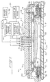
- Figure 1 is a cross-sectional view of a polishing head which incorporates a preferred embodiment of this invention.
- the polishing head is shown in a polishing position, in which both the semiconductor wafer and the wafer retainer are in contact with a polishing pad.
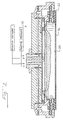
- Figure 2 is a cross-sectional view of the polishing head of Figure 1 showing the wafer carrier and the wafer retainer in a loading position, ready for wafer loading.
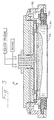
- Figure 3 is a cross-sectional view of the polishing head of Figure 1 showing the wafer carrier and the wafer retainer positioned in an insert replacement position.
- FIG. 1 shows a cross-sectional view of a polishing head 10 which incorporates a presently preferred embodiment of this invention.
- the polishing head 10 can be mounted to any suitable semiconductor wafer polishing machine, including any of the polishing machines discussed above, as well as others known now or in the future to those skilled in the art.
- the polishing head 10 includes a spindle 12 which is rigidly secured to a housing 14.
- the housing 14 is made up of an inner housing 16 and an outer housing 18.
- the inner housing 16 is rigidly secured to the spindle 12, as for example by bolts (not shown), and the outer housing 18 is rigidly secured to the inner housing 16, as for example by bolts (not shown).
- the housings 14, 18 can be formed of aluminum or stainless steel.
- the polishing head 10 also includes a wafer carrier 20 and a wafer retainer 22.
- the wafer carrier 20 is circular in shape and is movably mounted with respect to the housing 14 by a first annular diaphragm 24.
- the carrier can be formed of a ceramic such as alumina 995.
- the first diaphragm 24 can be formed of a resilient material such as BUNA material and is mechanically secured at its radially inner edge to the wafer carrier 20 and at its radially outer edge to the outer housing 18 by mounting rings 26.
- the housing 14, the wafer carrier 20 and the first diaphragm 24 cooperate to form a first fluid chamber 28 which is connected by a first fluid conduit 30 to a first adjustable pressure regulator 32.
- the first adjustable pressure regulator 32 is in turn connected to a source of pressurized fluid 34.
- the wafer retainer 22 is annular in shape, and movably mounted to the housing 14 by a second diaphragm 36, which is also annular in shape.
- the retainer 32 can be made for example of DELRIN AF®.
- the inner and outer marginal edges of the second diaphragm are secured to the outer housing 18 by mounting rings 38, and the central portion of the second diaphragm is secured to the wafer retainer 22 by mounting rings 40.
- the second diaphragm 36 and the housing 14 cooperate to form a second fluid chamber 42 that is bounded in part by the second diaphragm 36.
- This second fluid chamber 42 is connected by a second fluid conduit 44 to a second adjustable pressure regulator 46.
- the second adjustable pressure regulator 46 is connected both the source pressurized fluid 34 and to a vacuum source 48.
- the wafer carrier defines a wafer-supporting surface 50 which in the conventional manner supports an insert 52.
- a vacuum conduit 54 is conducted between the vacuum source 48 and the wafer carrier 20.
- the vacuum source 48 can be used to create a low pressure suction tending to hold a wafer W in place on the insert 52.
- the wafer retainer 22 substantially surrounds the wafer W to prevent undesired lateral movement between the wafer W and the polishing head 10.
- the first fluid chamber 28, the first fluid conduit 30 and the first diaphragm 24 cooperate with the wafer carrier 20 to form a first fluid actuator.
- the first adjustable pressure regulator 32 can be used to adjust the pressure of a fluid such as air in the first fluid chamber 28 in order to provide a dynamically adjustable biasing force tending to press the wafer W against the polishing pad P of the polishing machine.
- This first fluid actuator provides an evenly distributed force across substantially the entire upper surface of the wafer carrier 20, thereby minimizing uneven forces that might tend to distort the wafer carrier 20.
- the first diaphragm 24 performs both a mounting function in that it allows differential movement between the carrier 20 and the housing 14, and a sealing function in that it seals pressurized fluid in the first fluid chamber 28.
- the second diaphragm 36, the second fluid chamber 42 and the second fluid conduit 44 cooperate to form a second fluid actuator which can be used to adjust a biasing force tending to urge the wafer retainer 22 outwardly, toward the polishing pad P.
- the second fluid actuator is annular in shape and thereby applies evenly distributed biasing forces to the wafer retainer 22.
- the second diaphragm 36 performs two separate functions: movably mounting the wafer retainer 22 with respect to the housing 14, and sealing the second fluid chamber 42.
- the biasing forces on the wafer carrier 20 can be adjusted in a dynamic fashion during the wafer polishing operation with respect to the biasing forces on the wafer retainer 22. In this way, conditioning forces applied by the wafer retainer 22 to the polishing pad P and the flow of polishing slurry onto the marginal edges of the wafer W can be adjusted in real time during the polishing operation.
- the first and second adjustable pressure regulators 32, 46 operate as independently controllable valves.
- the widest variety of approaches can be used for the regulators 32, 46, including both manually controlled and computer controlled regulators.
- Other suitable means for adjusting fluid pressure may be substituted.
- Figure 1 shows the polishing head 10 in a use position, in which both the wafer W and the wafer retainer 22 are biased away from the housing 14, into contact with the polishing pad P. Note that in the polishing position both the wafer carrier 20 and the wafer retainer 22 are free to float over a limited range of movement, suspended by the respective diaphragms 24, 36.
- Figure 2 shows the polishing head 10 in a wafer loading position.
- the polishing head 10 has been moved away from the polishing pad and the pressurized fluids in the first and second fluid chambers 28, 42 bias the wafer carrier 20 and the wafer retainer 22 to extreme outer positions. In these positions, the wafer carrier 20 and the wafer retainer 22 form a wafer receiving pocket 56.
- Figure 3 shows the polishing head 10 in an insert-replacement position.
- the wafer carrier 20 is in the same position as in Figure 2.
- the second adjustable pressure regulator 46 ( Figure 1) has been used to apply a vacuum to the second fluid chamber 42 so as to move the wafer retainer 22 toward the housing 14. This moves the wafer retainer 22 inwardly of the wafer carrier 20, thereby exposing the insert 52 for ready removal and replacement.
- the polishing head 10 can be used in a wafer polishing operation by first mounting the wafer W on the wafer carrier 20 as shown in Figure 1.
- the wafer can either be a bare substrate (without photolithographic layers) or a substrate bearing one or more photolitographic layers.
- the polishing head 10 is then brought adjacent to the polishing pad P and relative movement is provided between the polishing head 10 and the polishing pad P. This relative movement can be any desired combination of linear and rotary motions.
- the adjustable pressure regulators 32, 46 are then used to bias the wafer carrier and therefore the wafer W against the polishing pad P and the retainer 22 against the polishing pad P.
- the relative biasing force on the wafer retainer 22 can be varied (either increased or decreased) with respect to the biasing force on the wafer carrier 20. In this way, the degree to which the polishing pad P is compressed before it contacts the wafer W can be adjusted, as can the rate at which polishing slurry is admitted to the marginal edge of the wafer W.
- the first and second fluid actuators described above operate as a means for creating a dynamically adjustable differential biasing force between the carrier 20 and the retainer 22. It should be recognized that other means can be used for dynamically adjusting the differential biasing force between these two elements.
- the entire polishing head 10 can be biased toward the polishing pad P and then either the carrier 20 or the retainer 22 can be movably mounted with respect the polishing head 10 and independently biased toward the pad P.
- either the carrier 20 or the retainer 22 can be rigidly mounted with respect to the housing 14.
- diaphragms 24, 36 can be used in substitution for the diaphragms 24, 36.
- a single diaphragm can be provided which supports both the carrier 20 and the retainer 22.
- bellows or pistons with sliding seals can be substituted for the diaphragms disclosed above.
- the diaphragms shown in the drawings are preferred, because they minimize friction between the moving elements and the housing, while providing an excellent seal.
- Fluid actuators using a pressurized liquid can be substituted for the fluid actuators discussed above, which preferably use pressurized gas such as air.
- the fluid actuators can be replaced with actuators such as mechanical springs having a means for adjusting the spring force provided by the mechanical spring.
- the polishing head of this invention can be adapted for use with a wide variety of semiconductor wafer polishing machines, including machines with polishing pads having both linear and rotary movements.
Landscapes
- Engineering & Computer Science (AREA)
- Mechanical Engineering (AREA)
- Mechanical Treatment Of Semiconductor (AREA)
- Finish Polishing, Edge Sharpening, And Grinding By Specific Grinding Devices (AREA)
Claims (13)
- Polierkopf (10) zum Polieren eines Halbleiterwafers (W), wobei der Polierkopf (10) umfasst:wobei sich eine erste und eine zweite Fluidleitung (30, 44) durch eine Spindel (12) hindurch erstrecken, die an dem Gehäuse (14) befestigt ist, so dass sie mit dem ersten bzw. dem zweiten Betätigungselement verbunden sind, wobei der Fluiddruck in dem ersten Betätigungselement in Bezug auf Fluiddruck in dem zweiten Betätigungselement reguliert werden kann.ein Gehäuse (14);einen Wafer-Träger (20), der beweglich an dem Gehäuse (14) angebracht ist, wobei der Wafer-Träger (20) eine Wafer-Tragefläche (50) umfasst;einen Wafer-Halter (22), der beweglich an dem Gehäuse (14) angebracht ist, wobei der Wafer-Halter (22) so geformt ist, dass er einen Wafer auf der Wafer-Tragefläche (50) festhält;ein erstes Fluid-Betätigungselement, das mit dem Wafer-Träger (20) verbunden ist, um den Wafer-Träger (20) in einer ersten ausgewählten Richtung in Bezug auf das Gehäuse (14) zu drücken;ein zweites Fluid-Betätigungselement, das mit dem Wafer-Halter (22) verbunden ist, um den Wafer-Halter (22) in einer zweiten ausgewählten Richtung in Bezug auf das Gehäuse (14) zu drücken; und
- Polierkopf (10) nach Anspruch 1, der des Weiteren ein erstes und ein zweites Ventil (32, 46) umfasst, die mit der ersten bzw. der zweiten Fluidleitung (30, 44) verbunden sind, wobei das erste und das zweite Ventil unabhängig voneinander gesteuert werden können.
- Polierkopf (10) nach Anspruch 1, wobei der Wafer-Träger (20) mittels einer ersten Membran (24) an dem Gehäuse (14) angebracht ist, und wobei der Wafer-Halter (22) mittels einer zweiten Membran (36) an dem Gehäuse (14) angebracht ist.
- Polierkopf (10) nach Anspruch 1, wobei das erste und das zweite Fluid-Betätigungselement eine erste bzw. eine zweite Fluidkammer (28, 42) umfassen, die mit der ersten bzw. der zweiten Fluidleitung (30, 44) verbunden sind, wobei die erste Fluidkammer (28) teilweise durch die erste Membran begrenzt wird und die zweite Fluidkammer (42) teilweise durch die zweite Membran begrenzt wird.
- Polierkopf (10) nach Anspruch 4, wobei die erste Fluidkammer (22) kreisförmig ist, und wobei die zweite Fluidkammer (42) ringförmig ist.
- Polierkopf (10) nach Anspruch 5, wobei der Wafer-Halter (22) ringförmig ist.
- Polierkopf (10) nach Anspruch 1, wobei die erste und die zweite Richtung zueinander fluchtend sind.
- Verfahren zum Steuern des Polierens eines Halbleiter-Wafers (W), wobei das Verfahren die folgenden Schritte umfasst:a) Anbringen eines Halbleiter-Wafers (W) an einem Wafer-Träger (20) eines Polierkopfes (10) nach einem der vorangehenden Ansprüche, wobei der Wafer wenigstens teilweise von einem Wafer-Halter (22) umgeben wird;b) Zuführen eines ersten Druckfluids zu dem Polierkopf (10), um den Wafer mit einer Wafer-Drückkraft an eine Polierscheibe (P) zu drücken;c) Zuführen eines zweiten Druckfluids zu dem Polierkopf (10), um den Wafer-Halter (22) mit einer Halter-Drückkraft an die Polierscheibe (P) zu drücken; undd) Regulieren der Halter-Drückkraft in Bezug auf die Wafer-Drückkraft durch Regulieren von Druck des zweiten Druckfluids in Bezug auf Druck des ersten Druckfluids.
- Verfahren nach Anspruch 8, wobei Schritt d) während eines Wafer-Poliervorgangs ausgeführt wird.
Applications Claiming Priority (2)
| Application Number | Priority Date | Filing Date | Title |
|---|---|---|---|
| US59086196A | 1996-01-24 | 1996-01-24 | |
| US590861 | 1996-01-24 |
Publications (2)
| Publication Number | Publication Date |
|---|---|
| EP0786310A1 EP0786310A1 (de) | 1997-07-30 |
| EP0786310B1 true EP0786310B1 (de) | 2002-12-04 |
Family
ID=24364029
Family Applications (1)
| Application Number | Title | Priority Date | Filing Date |
|---|---|---|---|
| EP97300080A Expired - Lifetime EP0786310B1 (de) | 1996-01-24 | 1997-01-08 | Halbleiterscheiben-Polierkopf |
Country Status (5)
| Country | Link |
|---|---|
| US (1) | US5803799A (de) |
| EP (1) | EP0786310B1 (de) |
| JP (1) | JPH09201763A (de) |
| AT (1) | ATE228915T1 (de) |
| DE (1) | DE69717510T2 (de) |
Families Citing this family (96)
| Publication number | Priority date | Publication date | Assignee | Title |
|---|---|---|---|---|
| JP3183388B2 (ja) * | 1996-07-12 | 2001-07-09 | 株式会社東京精密 | 半導体ウェーハ研磨装置 |
| US6146259A (en) * | 1996-11-08 | 2000-11-14 | Applied Materials, Inc. | Carrier head with local pressure control for a chemical mechanical polishing apparatus |
| US6183354B1 (en) | 1996-11-08 | 2001-02-06 | Applied Materials, Inc. | Carrier head with a flexible membrane for a chemical mechanical polishing system |
| JP3705670B2 (ja) * | 1997-02-19 | 2005-10-12 | 株式会社荏原製作所 | ポリッシング装置及び方法 |
| US6244946B1 (en) | 1997-04-08 | 2001-06-12 | Lam Research Corporation | Polishing head with removable subcarrier |
| US6425812B1 (en) | 1997-04-08 | 2002-07-30 | Lam Research Corporation | Polishing head for chemical mechanical polishing using linear planarization technology |
| EP0881039B1 (de) | 1997-05-28 | 2003-04-16 | Tokyo Seimitsu Co.,Ltd. | Halbleiterscheibe Poliervorrichtung mit Halterring |
| US5964653A (en) * | 1997-07-11 | 1999-10-12 | Applied Materials, Inc. | Carrier head with a flexible membrane for a chemical mechanical polishing system |
| SG66487A1 (en) | 1997-07-11 | 1999-07-20 | Tokyo Seimitsu Co Ltd | Wafer polishing apparatus |
| US5916015A (en) * | 1997-07-25 | 1999-06-29 | Speedfam Corporation | Wafer carrier for semiconductor wafer polishing machine |
| US6113479A (en) | 1997-07-25 | 2000-09-05 | Obsidian, Inc. | Wafer carrier for chemical mechanical planarization polishing |
| MY120754A (en) * | 1997-08-11 | 2005-11-30 | Tokyo Seimitsu Co Ltd | Wafer polishing apparatus |
| TW434095B (en) * | 1997-08-11 | 2001-05-16 | Tokyo Seimitsu Co Ltd | Wafer polishing apparatus |
| US5989103A (en) * | 1997-09-19 | 1999-11-23 | Applied Materials, Inc. | Magnetic carrier head for chemical mechanical polishing |
| US6080040A (en) * | 1997-11-05 | 2000-06-27 | Aplex Group | Wafer carrier head with inflatable bladder and attack angle control for polishing |
| JP3006568B2 (ja) * | 1997-12-04 | 2000-02-07 | 日本電気株式会社 | ウエハ研磨装置および研磨方法 |
| US6068548A (en) * | 1997-12-17 | 2000-05-30 | Intel Corporation | Mechanically stabilized retaining ring for chemical mechanical polishing |
| US6531397B1 (en) | 1998-01-09 | 2003-03-11 | Lsi Logic Corporation | Method and apparatus for using across wafer back pressure differentials to influence the performance of chemical mechanical polishing |
| JPH11285966A (ja) * | 1998-04-02 | 1999-10-19 | Speedfam-Ipec Co Ltd | キャリア及びcmp装置 |
| US5985094A (en) * | 1998-05-12 | 1999-11-16 | Speedfam-Ipec Corporation | Semiconductor wafer carrier |
| US6106379A (en) * | 1998-05-12 | 2000-08-22 | Speedfam-Ipec Corporation | Semiconductor wafer carrier with automatic ring extension |
| US6113480A (en) * | 1998-06-02 | 2000-09-05 | Taiwan Semiconductor Manufacturing Co., Ltd | Apparatus for polishing semiconductor wafers and method of testing same |
| US6251215B1 (en) * | 1998-06-03 | 2001-06-26 | Applied Materials, Inc. | Carrier head with a multilayer retaining ring for chemical mechanical polishing |
| US6159079A (en) * | 1998-09-08 | 2000-12-12 | Applied Materials, Inc. | Carrier head for chemical mechanical polishing a substrate |
| US6210255B1 (en) | 1998-09-08 | 2001-04-03 | Applied Materials, Inc. | Carrier head for chemical mechanical polishing a substrate |
| SG95604A1 (en) * | 1998-09-25 | 2003-04-23 | Tdk Corp | Apparatus and method for processing slider, load applying apparatus and auxiliary device for processing slider |
| US6347979B1 (en) * | 1998-09-29 | 2002-02-19 | Vsli Technology, Inc. | Slurry dispensing carrier ring |
| JP2000187832A (ja) * | 1998-10-05 | 2000-07-04 | Exclusive Design Co Inc | 磁気ディスク及び他の基板を自動研磨する方法及び装置 |
| US6244942B1 (en) | 1998-10-09 | 2001-06-12 | Applied Materials, Inc. | Carrier head with a flexible membrane and adjustable edge pressure |
| US6132298A (en) | 1998-11-25 | 2000-10-17 | Applied Materials, Inc. | Carrier head with edge control for chemical mechanical polishing |
| US6277014B1 (en) | 1998-10-09 | 2001-08-21 | Applied Materials, Inc. | Carrier head with a flexible membrane for chemical mechanical polishing |
| US6220930B1 (en) * | 1998-11-03 | 2001-04-24 | United Microelectronics Corp. | Wafer polishing head |
| US6165058A (en) * | 1998-12-09 | 2000-12-26 | Applied Materials, Inc. | Carrier head for chemical mechanical polishing |
| SG82058A1 (en) * | 1998-12-30 | 2001-07-24 | Applied Materials Inc | Carrier head with controllable pressure and loading area for chemical mechanical polishing |
| US6422927B1 (en) | 1998-12-30 | 2002-07-23 | Applied Materials, Inc. | Carrier head with controllable pressure and loading area for chemical mechanical polishing |
| US6162116A (en) * | 1999-01-23 | 2000-12-19 | Applied Materials, Inc. | Carrier head for chemical mechanical polishing |
| US6179709B1 (en) | 1999-02-04 | 2001-01-30 | Applied Materials, Inc. | In-situ monitoring of linear substrate polishing operations |
| TW436378B (en) * | 1999-02-05 | 2001-05-28 | Mitsubishi Materials Corp | Wafer polishing apparatus and method for making a wafer |
| US6645050B1 (en) * | 1999-02-25 | 2003-11-11 | Applied Materials, Inc. | Multimode substrate carrier |
| US6231428B1 (en) * | 1999-03-03 | 2001-05-15 | Mitsubishi Materials Corporation | Chemical mechanical polishing head assembly having floating wafer carrier and retaining ring |
| US6368189B1 (en) | 1999-03-03 | 2002-04-09 | Mitsubishi Materials Corporation | Apparatus and method for chemical-mechanical polishing (CMP) head having direct pneumatic wafer polishing pressure |
| US6113468A (en) * | 1999-04-06 | 2000-09-05 | Speedfam-Ipec Corporation | Wafer planarization carrier having floating pad load ring |
| US6431968B1 (en) | 1999-04-22 | 2002-08-13 | Applied Materials, Inc. | Carrier head with a compressible film |
| WO2000078504A1 (en) * | 1999-06-19 | 2000-12-28 | Speedfam-Ipec Corporation | Method and apparatus for increasing the lifetime of a workpiece retaining structure and conditioning a polishing surface |
| US6224472B1 (en) * | 1999-06-24 | 2001-05-01 | Samsung Austin Semiconductor, L.P. | Retaining ring for chemical mechanical polishing |
| US6241593B1 (en) * | 1999-07-09 | 2001-06-05 | Applied Materials, Inc. | Carrier head with pressurizable bladder |
| US6358121B1 (en) | 1999-07-09 | 2002-03-19 | Applied Materials, Inc. | Carrier head with a flexible membrane and an edge load ring |
| US6494774B1 (en) | 1999-07-09 | 2002-12-17 | Applied Materials, Inc. | Carrier head with pressure transfer mechanism |
| US6855043B1 (en) | 1999-07-09 | 2005-02-15 | Applied Materials, Inc. | Carrier head with a modified flexible membrane |
| WO2001007208A1 (en) * | 1999-07-28 | 2001-02-01 | Mitsubishi Materials Corporation | Cmp polishing head with three chambers and method for using the same |
| US6663466B2 (en) | 1999-11-17 | 2003-12-16 | Applied Materials, Inc. | Carrier head with a substrate detector |
| US6375549B1 (en) | 2000-03-17 | 2002-04-23 | Motorola, Inc. | Polishing head for wafer, and method for polishing |
| US6361419B1 (en) | 2000-03-27 | 2002-03-26 | Applied Materials, Inc. | Carrier head with controllable edge pressure |
| US6450868B1 (en) | 2000-03-27 | 2002-09-17 | Applied Materials, Inc. | Carrier head with multi-part flexible membrane |
| US6666756B1 (en) * | 2000-03-31 | 2003-12-23 | Lam Research Corporation | Wafer carrier head assembly |
| US7140956B1 (en) | 2000-03-31 | 2006-11-28 | Speedfam-Ipec Corporation | Work piece carrier with adjustable pressure zones and barriers and a method of planarizing a work piece |
| US6390905B1 (en) * | 2000-03-31 | 2002-05-21 | Speedfam-Ipec Corporation | Workpiece carrier with adjustable pressure zones and barriers |
| US6354928B1 (en) * | 2000-04-21 | 2002-03-12 | Agere Systems Guardian Corp. | Polishing apparatus with carrier ring and carrier head employing like polarities |
| US6436828B1 (en) | 2000-05-04 | 2002-08-20 | Applied Materials, Inc. | Chemical mechanical polishing using magnetic force |
| US6558232B1 (en) * | 2000-05-12 | 2003-05-06 | Multi-Planar Technologies, Inc. | System and method for CMP having multi-pressure zone loading for improved edge and annular zone material removal control |
| US6409579B1 (en) * | 2000-05-31 | 2002-06-25 | Koninklijke Philips Electronics N.V. | Method and apparatus for conditioning a polish pad at the point of polish and for dispensing slurry at the point of polish |
| US6540592B1 (en) | 2000-06-29 | 2003-04-01 | Speedfam-Ipec Corporation | Carrier head with reduced moment wear ring |
| US6447380B1 (en) | 2000-06-30 | 2002-09-10 | Lam Research Corporation | Polishing apparatus and substrate retainer ring providing continuous slurry distribution |
| US6722965B2 (en) | 2000-07-11 | 2004-04-20 | Applied Materials Inc. | Carrier head with flexible membranes to provide controllable pressure and loading area |
| US7198561B2 (en) * | 2000-07-25 | 2007-04-03 | Applied Materials, Inc. | Flexible membrane for multi-chamber carrier head |
| US6857945B1 (en) | 2000-07-25 | 2005-02-22 | Applied Materials, Inc. | Multi-chamber carrier head with a flexible membrane |
| US20040005842A1 (en) * | 2000-07-25 | 2004-01-08 | Chen Hung Chih | Carrier head with flexible membrane |
| US6419567B1 (en) | 2000-08-14 | 2002-07-16 | Semiconductor 300 Gmbh & Co. Kg | Retaining ring for chemical-mechanical polishing (CMP) head, polishing apparatus, slurry cycle system, and method |
| US6652357B1 (en) | 2000-09-22 | 2003-11-25 | Lam Research Corporation | Methods for controlling retaining ring and wafer head tilt for chemical mechanical polishing |
| US6443815B1 (en) * | 2000-09-22 | 2002-09-03 | Lam Research Corporation | Apparatus and methods for controlling pad conditioning head tilt for chemical mechanical polishing |
| JP4818505B2 (ja) * | 2000-10-19 | 2011-11-16 | 不二越機械工業株式会社 | ウェーハ研磨ヘッド |
| US6447368B1 (en) | 2000-11-20 | 2002-09-10 | Speedfam-Ipec Corporation | Carriers with concentric balloons supporting a diaphragm |
| US6468131B1 (en) | 2000-11-28 | 2002-10-22 | Speedfam-Ipec Corporation | Method to mathematically characterize a multizone carrier |
| US6910949B1 (en) | 2001-04-25 | 2005-06-28 | Lam Research Corporation | Spherical cap-shaped polishing head in a chemical mechanical polishing apparatus for semiconductor wafers |
| US6582277B2 (en) | 2001-05-01 | 2003-06-24 | Speedfam-Ipec Corporation | Method for controlling a process in a multi-zonal apparatus |
| US6722942B1 (en) | 2001-05-21 | 2004-04-20 | Advanced Micro Devices, Inc. | Chemical mechanical polishing with electrochemical control |
| US7217175B2 (en) * | 2001-05-29 | 2007-05-15 | Ebara Corporation | Polishing apparatus and polishing method |
| US6893327B2 (en) * | 2001-06-04 | 2005-05-17 | Multi Planar Technologies, Inc. | Chemical mechanical polishing apparatus and method having a retaining ring with a contoured surface |
| KR100421445B1 (ko) * | 2001-09-28 | 2004-03-09 | 삼성전자주식회사 | 연마 헤드 조립 방법 및 연마 헤드 조립 시의 공기 누설검사장치 |
| US6890249B1 (en) | 2001-12-27 | 2005-05-10 | Applied Materials, Inc. | Carrier head with edge load retaining ring |
| US6872130B1 (en) | 2001-12-28 | 2005-03-29 | Applied Materials Inc. | Carrier head with non-contact retainer |
| US20030182015A1 (en) * | 2002-03-19 | 2003-09-25 | Domaille Michael D. | Polisher |
| US6689258B1 (en) | 2002-04-30 | 2004-02-10 | Advanced Micro Devices, Inc. | Electrochemically generated reactants for chemical mechanical planarization |
| US6790123B2 (en) | 2002-05-16 | 2004-09-14 | Speedfam-Ipec Corporation | Method for processing a work piece in a multi-zonal processing apparatus |
| WO2004033152A1 (en) * | 2002-10-11 | 2004-04-22 | Semplastics, L.L.C. | Retaining ring for use on a carrier of a polishing apparatus |
| US7001245B2 (en) * | 2003-03-07 | 2006-02-21 | Applied Materials Inc. | Substrate carrier with a textured membrane |
| US20060180486A1 (en) * | 2003-04-21 | 2006-08-17 | Bennett David W | Modular panel and storage system for flat items such as media discs and holders therefor |
| KR100600231B1 (ko) * | 2003-07-12 | 2006-07-13 | 동부일렉트로닉스 주식회사 | 씨엠피 폴리싱 헤드 및 그 동작방법 |
| US7255771B2 (en) * | 2004-03-26 | 2007-08-14 | Applied Materials, Inc. | Multiple zone carrier head with flexible membrane |
| US6935938B1 (en) | 2004-03-31 | 2005-08-30 | Lam Research Corporation | Multiple-conditioning member device for chemical mechanical planarization conditioning |
| EP2797109B1 (de) | 2004-11-01 | 2018-02-28 | Ebara Corporation | Poliervorrichtung |
| US7101272B2 (en) * | 2005-01-15 | 2006-09-05 | Applied Materials, Inc. | Carrier head for thermal drift compensation |
| JP4814677B2 (ja) | 2006-03-31 | 2011-11-16 | 株式会社荏原製作所 | 基板保持装置および研磨装置 |
| KR101617716B1 (ko) * | 2008-03-25 | 2016-05-03 | 어플라이드 머티어리얼스, 인코포레이티드 | 개량된 캐리어 헤드 멤브레인 |
| US7749052B2 (en) * | 2008-09-08 | 2010-07-06 | Applied Materials, Inc. | Carrier head using flexure restraints for retaining ring alignment |
| US10160093B2 (en) | 2008-12-12 | 2018-12-25 | Applied Materials, Inc. | Carrier head membrane roughness to control polishing rate |
Family Cites Families (19)
| Publication number | Priority date | Publication date | Assignee | Title |
|---|---|---|---|---|
| US3579916A (en) * | 1968-11-15 | 1971-05-25 | Speedfam Corp | Polishing machine |
| US3731435A (en) * | 1971-02-09 | 1973-05-08 | Speedfam Corp | Polishing machine load plate |
| JPS55157473A (en) * | 1979-05-22 | 1980-12-08 | Nippon Telegr & Teleph Corp <Ntt> | Polishing method |
| US4519168A (en) * | 1979-09-18 | 1985-05-28 | Speedfam Corporation | Liquid waxless fixturing of microsize wafers |
| JPS59187456A (ja) * | 1983-04-08 | 1984-10-24 | Fujitsu Ltd | 半導体基板の研摩方法 |
| US5205082A (en) * | 1991-12-20 | 1993-04-27 | Cybeq Systems, Inc. | Wafer polisher head having floating retainer ring |
| US5329732A (en) | 1992-06-15 | 1994-07-19 | Speedfam Corporation | Wafer polishing method and apparatus |
| EP0911115B1 (de) * | 1992-09-24 | 2003-11-26 | Ebara Corporation | Poliergerät |
| JP3370112B2 (ja) * | 1992-10-12 | 2003-01-27 | 不二越機械工業株式会社 | ウエハーの研磨装置 |
| DE69316849T2 (de) * | 1992-11-27 | 1998-09-10 | Toshiba Kawasaki Kk | Verfahren und Gerät zum Polieren eines Werkstückes |
| US5377451A (en) * | 1993-02-23 | 1995-01-03 | Memc Electronic Materials, Inc. | Wafer polishing apparatus and method |
| US5329734A (en) | 1993-04-30 | 1994-07-19 | Motorola, Inc. | Polishing pads used to chemical-mechanical polish a semiconductor substrate |
| US5443416A (en) * | 1993-09-09 | 1995-08-22 | Cybeq Systems Incorporated | Rotary union for coupling fluids in a wafer polishing apparatus |
| US5423716A (en) * | 1994-01-05 | 1995-06-13 | Strasbaugh; Alan | Wafer-handling apparatus having a resilient membrane which holds wafer when a vacuum is applied |
| US5449316A (en) * | 1994-01-05 | 1995-09-12 | Strasbaugh; Alan | Wafer carrier for film planarization |
| US5423558A (en) * | 1994-03-24 | 1995-06-13 | Ipec/Westech Systems, Inc. | Semiconductor wafer carrier and method |
| JP3158934B2 (ja) * | 1995-02-28 | 2001-04-23 | 三菱マテリアル株式会社 | ウェーハ研磨装置 |
| US6024630A (en) * | 1995-06-09 | 2000-02-15 | Applied Materials, Inc. | Fluid-pressure regulated wafer polishing head |
| JP3724869B2 (ja) * | 1995-10-09 | 2005-12-07 | 株式会社荏原製作所 | ポリッシング装置および方法 |
-
1997
- 1997-01-08 DE DE69717510T patent/DE69717510T2/de not_active Expired - Fee Related
- 1997-01-08 EP EP97300080A patent/EP0786310B1/de not_active Expired - Lifetime
- 1997-01-08 AT AT97300080T patent/ATE228915T1/de not_active IP Right Cessation
- 1997-01-23 JP JP1036997A patent/JPH09201763A/ja active Pending
- 1997-06-20 US US08/879,862 patent/US5803799A/en not_active Expired - Lifetime
Also Published As
| Publication number | Publication date |
|---|---|
| EP0786310A1 (de) | 1997-07-30 |
| JPH09201763A (ja) | 1997-08-05 |
| US5803799A (en) | 1998-09-08 |
| DE69717510D1 (de) | 2003-01-16 |
| ATE228915T1 (de) | 2002-12-15 |
| DE69717510T2 (de) | 2003-10-02 |
Similar Documents
| Publication | Publication Date | Title |
|---|---|---|
| EP0786310B1 (de) | Halbleiterscheiben-Polierkopf | |
| US5913714A (en) | Method for dressing a polishing pad during polishing of a semiconductor wafer | |
| US6290577B1 (en) | Fluid pressure regulated wafer polishing head | |
| US7883397B2 (en) | Substrate retainer | |
| US7198561B2 (en) | Flexible membrane for multi-chamber carrier head | |
| US6132298A (en) | Carrier head with edge control for chemical mechanical polishing | |
| US6113468A (en) | Wafer planarization carrier having floating pad load ring | |
| US6890249B1 (en) | Carrier head with edge load retaining ring | |
| US6431968B1 (en) | Carrier head with a compressible film | |
| EP1066922A2 (de) | Trägerplatte mit aufblasbarem Balg | |
| US6358121B1 (en) | Carrier head with a flexible membrane and an edge load ring | |
| US6540592B1 (en) | Carrier head with reduced moment wear ring | |
| KR20040023228A (ko) | 화학적 기계적 평탄화 기계의 폴리싱 헤드 | |
| US6641461B2 (en) | Chemical mechanical polishing apparatus having edge, center and annular zone control of material removal | |
| CN218891684U (zh) | 一种用于化学机械抛光的弹性膜和承载头 | |
| CN116038556A (zh) | 一种用于化学机械抛光的弹性膜和承载头 | |
| CN116141192A (zh) | 一种用于化学机械抛光的弹性膜和承载头 |
Legal Events
| Date | Code | Title | Description |
|---|---|---|---|
| PUAI | Public reference made under article 153(3) epc to a published international application that has entered the european phase |
Free format text: ORIGINAL CODE: 0009012 |
|
| AK | Designated contracting states |
Kind code of ref document: A1 Designated state(s): AT BE CH DE DK ES FI FR GB GR IE IT LI LU MC NL PT SE |
|
| AX | Request for extension of the european patent |
Free format text: AL PAYMENT 970120;LT PAYMENT 970120;LV PAYMENT 970120;RO PAYMENT 970120;SI PAYMENT 970120 |
|
| 17P | Request for examination filed |
Effective date: 19970929 |
|
| 17Q | First examination report despatched |
Effective date: 19990608 |
|
| RAP1 | Party data changed (applicant data changed or rights of an application transferred) |
Owner name: LAM RESEARCH CORPORATION |
|
| GRAG | Despatch of communication of intention to grant |
Free format text: ORIGINAL CODE: EPIDOS AGRA |
|
| GRAG | Despatch of communication of intention to grant |
Free format text: ORIGINAL CODE: EPIDOS AGRA |
|
| GRAH | Despatch of communication of intention to grant a patent |
Free format text: ORIGINAL CODE: EPIDOS IGRA |
|
| GRAH | Despatch of communication of intention to grant a patent |
Free format text: ORIGINAL CODE: EPIDOS IGRA |
|
| GRAA | (expected) grant |
Free format text: ORIGINAL CODE: 0009210 |
|
| AK | Designated contracting states |
Kind code of ref document: B1 Designated state(s): AT BE CH DE DK ES FI FR GB GR IE IT LI LU MC NL PT SE |
|
| AX | Request for extension of the european patent |
Free format text: AL PAYMENT 19970120;LT PAYMENT 19970120;LV PAYMENT 19970120;RO PAYMENT 19970120;SI PAYMENT 19970120 |
|
| PG25 | Lapsed in a contracting state [announced via postgrant information from national office to epo] |
Ref country code: LI Free format text: LAPSE BECAUSE OF FAILURE TO SUBMIT A TRANSLATION OF THE DESCRIPTION OR TO PAY THE FEE WITHIN THE PRESCRIBED TIME-LIMIT Effective date: 20021204 Ref country code: GR Free format text: LAPSE BECAUSE OF FAILURE TO SUBMIT A TRANSLATION OF THE DESCRIPTION OR TO PAY THE FEE WITHIN THE PRESCRIBED TIME-LIMIT Effective date: 20021204 Ref country code: FI Free format text: LAPSE BECAUSE OF FAILURE TO SUBMIT A TRANSLATION OF THE DESCRIPTION OR TO PAY THE FEE WITHIN THE PRESCRIBED TIME-LIMIT Effective date: 20021204 Ref country code: CH Free format text: LAPSE BECAUSE OF FAILURE TO SUBMIT A TRANSLATION OF THE DESCRIPTION OR TO PAY THE FEE WITHIN THE PRESCRIBED TIME-LIMIT Effective date: 20021204 Ref country code: AT Free format text: LAPSE BECAUSE OF FAILURE TO SUBMIT A TRANSLATION OF THE DESCRIPTION OR TO PAY THE FEE WITHIN THE PRESCRIBED TIME-LIMIT Effective date: 20021204 |
|
| REF | Corresponds to: |
Ref document number: 228915 Country of ref document: AT Date of ref document: 20021215 Kind code of ref document: T |
|
| REG | Reference to a national code |
Ref country code: GB Ref legal event code: FG4D |
|
| REG | Reference to a national code |
Ref country code: CH Ref legal event code: EP |
|
| PG25 | Lapsed in a contracting state [announced via postgrant information from national office to epo] |
Ref country code: LU Free format text: LAPSE BECAUSE OF NON-PAYMENT OF DUE FEES Effective date: 20030108 Ref country code: IE Free format text: LAPSE BECAUSE OF NON-PAYMENT OF DUE FEES Effective date: 20030108 |
|
| REG | Reference to a national code |
Ref country code: IE Ref legal event code: FG4D |
|
| REF | Corresponds to: |
Ref document number: 69717510 Country of ref document: DE Date of ref document: 20030116 |
|
| PG25 | Lapsed in a contracting state [announced via postgrant information from national office to epo] |
Ref country code: MC Free format text: LAPSE BECAUSE OF NON-PAYMENT OF DUE FEES Effective date: 20030131 |
|
| PG25 | Lapsed in a contracting state [announced via postgrant information from national office to epo] |
Ref country code: SE Free format text: LAPSE BECAUSE OF FAILURE TO SUBMIT A TRANSLATION OF THE DESCRIPTION OR TO PAY THE FEE WITHIN THE PRESCRIBED TIME-LIMIT Effective date: 20030304 Ref country code: DK Free format text: LAPSE BECAUSE OF FAILURE TO SUBMIT A TRANSLATION OF THE DESCRIPTION OR TO PAY THE FEE WITHIN THE PRESCRIBED TIME-LIMIT Effective date: 20030304 |
|
| PG25 | Lapsed in a contracting state [announced via postgrant information from national office to epo] |
Ref country code: PT Free format text: LAPSE BECAUSE OF FAILURE TO SUBMIT A TRANSLATION OF THE DESCRIPTION OR TO PAY THE FEE WITHIN THE PRESCRIBED TIME-LIMIT Effective date: 20030305 |
|
| LTIE | Lt: invalidation of european patent or patent extension |
Effective date: 20021204 |
|
| ET | Fr: translation filed | ||
| REG | Reference to a national code |
Ref country code: CH Ref legal event code: PL |
|
| PG25 | Lapsed in a contracting state [announced via postgrant information from national office to epo] |
Ref country code: ES Free format text: LAPSE BECAUSE OF FAILURE TO SUBMIT A TRANSLATION OF THE DESCRIPTION OR TO PAY THE FEE WITHIN THE PRESCRIBED TIME-LIMIT Effective date: 20030627 |
|
| PLBE | No opposition filed within time limit |
Free format text: ORIGINAL CODE: 0009261 |
|
| STAA | Information on the status of an ep patent application or granted ep patent |
Free format text: STATUS: NO OPPOSITION FILED WITHIN TIME LIMIT |
|
| REG | Reference to a national code |
Ref country code: IE Ref legal event code: MM4A |
|
| 26N | No opposition filed |
Effective date: 20030905 |
|
| PGFP | Annual fee paid to national office [announced via postgrant information from national office to epo] |
Ref country code: NL Payment date: 20070124 Year of fee payment: 11 |
|
| PGFP | Annual fee paid to national office [announced via postgrant information from national office to epo] |
Ref country code: GB Payment date: 20070125 Year of fee payment: 11 |
|
| PGFP | Annual fee paid to national office [announced via postgrant information from national office to epo] |
Ref country code: DE Payment date: 20070228 Year of fee payment: 11 |
|
| PGFP | Annual fee paid to national office [announced via postgrant information from national office to epo] |
Ref country code: BE Payment date: 20070301 Year of fee payment: 11 |
|
| PGFP | Annual fee paid to national office [announced via postgrant information from national office to epo] |
Ref country code: IT Payment date: 20070521 Year of fee payment: 11 |
|
| PGFP | Annual fee paid to national office [announced via postgrant information from national office to epo] |
Ref country code: FR Payment date: 20070117 Year of fee payment: 11 |
|
| BERE | Be: lapsed |
Owner name: *LAM RESEARCH CORP. Effective date: 20080131 |
|
| GBPC | Gb: european patent ceased through non-payment of renewal fee |
Effective date: 20080108 |
|
| NLV4 | Nl: lapsed or anulled due to non-payment of the annual fee |
Effective date: 20080801 |
|
| PG25 | Lapsed in a contracting state [announced via postgrant information from national office to epo] |
Ref country code: NL Free format text: LAPSE BECAUSE OF NON-PAYMENT OF DUE FEES Effective date: 20080801 Ref country code: DE Free format text: LAPSE BECAUSE OF NON-PAYMENT OF DUE FEES Effective date: 20080801 |
|
| REG | Reference to a national code |
Ref country code: FR Ref legal event code: ST Effective date: 20081029 |
|
| PG25 | Lapsed in a contracting state [announced via postgrant information from national office to epo] |
Ref country code: GB Free format text: LAPSE BECAUSE OF NON-PAYMENT OF DUE FEES Effective date: 20080108 |
|
| PG25 | Lapsed in a contracting state [announced via postgrant information from national office to epo] |
Ref country code: BE Free format text: LAPSE BECAUSE OF NON-PAYMENT OF DUE FEES Effective date: 20080131 |
|
| PG25 | Lapsed in a contracting state [announced via postgrant information from national office to epo] |
Ref country code: FR Free format text: LAPSE BECAUSE OF NON-PAYMENT OF DUE FEES Effective date: 20080131 |
|
| PG25 | Lapsed in a contracting state [announced via postgrant information from national office to epo] |
Ref country code: IT Free format text: LAPSE BECAUSE OF NON-PAYMENT OF DUE FEES Effective date: 20080108 |