EP0785569B1 - Réacteur à plasma - Google Patents
Réacteur à plasma Download PDFInfo
- Publication number
- EP0785569B1 EP0785569B1 EP96120621A EP96120621A EP0785569B1 EP 0785569 B1 EP0785569 B1 EP 0785569B1 EP 96120621 A EP96120621 A EP 96120621A EP 96120621 A EP96120621 A EP 96120621A EP 0785569 B1 EP0785569 B1 EP 0785569B1
- Authority
- EP
- European Patent Office
- Prior art keywords
- plasma
- strand material
- rollers
- roller
- plasma reactor
- Prior art date
- Legal status (The legal status is an assumption and is not a legal conclusion. Google has not performed a legal analysis and makes no representation as to the accuracy of the status listed.)
- Expired - Lifetime
Links
Images
Classifications
-
- H—ELECTRICITY
- H01—ELECTRIC ELEMENTS
- H01J—ELECTRIC DISCHARGE TUBES OR DISCHARGE LAMPS
- H01J37/00—Discharge tubes with provision for introducing objects or material to be exposed to the discharge, e.g. for the purpose of examination or processing thereof
- H01J37/32—Gas-filled discharge tubes
- H01J37/32431—Constructional details of the reactor
- H01J37/32733—Means for moving the material to be treated
- H01J37/32752—Means for moving the material to be treated for moving the material across the discharge
- H01J37/32761—Continuous moving
- H01J37/3277—Continuous moving of continuous material
-
- D—TEXTILES; PAPER
- D06—TREATMENT OF TEXTILES OR THE LIKE; LAUNDERING; FLEXIBLE MATERIALS NOT OTHERWISE PROVIDED FOR
- D06B—TREATING TEXTILE MATERIALS USING LIQUIDS, GASES OR VAPOURS
- D06B17/00—Storing of textile materials in association with the treatment of the materials by liquids, gases or vapours
- D06B17/005—Storing of textile materials in association with the treatment of the materials by liquids, gases or vapours in helical form
-
- D—TEXTILES; PAPER
- D06—TREATMENT OF TEXTILES OR THE LIKE; LAUNDERING; FLEXIBLE MATERIALS NOT OTHERWISE PROVIDED FOR
- D06M—TREATMENT, NOT PROVIDED FOR ELSEWHERE IN CLASS D06, OF FIBRES, THREADS, YARNS, FABRICS, FEATHERS OR FIBROUS GOODS MADE FROM SUCH MATERIALS
- D06M10/00—Physical treatment of fibres, threads, yarns, fabrics or fibrous goods made from such materials, e.g. by ultrasonic waves, corona discharge, irradiation, electric currents or magnetic fields; Physical treatment combined with treatment with chemical compounds or elements
- D06M10/02—Sonic or ultrasonic waves; Corona discharge
- D06M10/025—Corona discharge or low temperature plasma
Definitions
- the invention relates to a plasma reactor for flexible strand material.
- Flexible strand materials for example wires, irregular fiber bundles, such as e.g. Natural wool combing, or regular fiber knits and braids, e.g. Technical textiles are used as raw materials and intermediates in many industries.
- chemical processing methods are often used to modify the surface of the strand material. Since chemical processing methods are often associated with severe environmental impact, attempts have been made to subject said strand materials to a plasma treatment (PVD, CVD, plasma etching) which results in a lower environmental impact compared to chemical processing methods.
- Plasma reactors In order to be able to subject flexible strand materials to a continuous plasma treatment, they are used as pilot plants Plasma reactors have been developed, which have a reactor space in which the strand material is introduced via a passage for the inlet and from which it is led out via a passage for the exit. In the interior of the reactor space electrodes are arranged, which generate a plasma, through which the strand material is moved.
- the strand material to be processed is exposed for several minutes to the action of the plasma.
- Such a long processing time can be achieved if the strand material is guided in the interior of the plasma reactor in a meandering way.
- the leadership takes place in known plasma reactors by means of guide elements that guide the strand material along a processing path.
- the known plasma reactors are very elongate devices in which a plurality of cascaded electrodes are provided, each generating small local plasmas.
- the plurality of electrodes is difficult to control and there is a risk of local thermal destruction of the strand material to be processed.
- the guiding material guiding the strand material have a negative effect on the formation of the plasma and its controllability.
- the invention has for its object to provide a compact plasma reactor for flexible strand material available, which allows a uniform and gentle processing of the flexible strand material.
- the at least one guide element is a roller around which the strand material rotates in a plurality of axially offset turns.
- the plasma sources are arranged such that the plasma generated by them simultaneously detects portions of at least two axially staggered turns. Due to the multiple circulation of the strand material around the same roller, a long processing path is available in the interior of the reactor space, the length of which exceeds the length of the plasma reactor by a multiple. The long processing path allows long processing times with a compact design of the plasma reactor.
- the plasma sources preferably electrodes, are suitably designed and arranged to produce a spatially extended plasma which is used simultaneously for processing a plurality of sections of strand material.
- the spatially extended plasma is easier to control because of its size over a plasma whose extent is only in the order of magnitude of the width or thickness of the strand material. Because of the multiple deflection of the strand material, the strand material is also particularly accessible. A working the strand material plasma is not disturbed by internals or the like in its training.
- the electrodes are arranged in the area of free conveying paths, their plasma can wrap the strand material in sections and process it particularly uniformly. In such an embodiment, moreover, the formation of the plasma is not even affected by the rollers. For the adjustment of the plasma, only the quality of the strand material is to be taken into account as a significant disturbance variable. The same advantages also result for a plasma which is produced without electrodes, e.g. in a microwave plasma.
- a plasma reactor from which the preamble of claim 1 proceeds, is described in WO 95/19837 ,
- the plasma reactor contains two spaced-apart rollers in a reactor space, around which the strand material is guided alternately.
- the reactor space there are electrodes for the production of a plasma, in particular in the area between the two rolls.
- DE-A-2400587 describes a plasma reactor with a single roller around which the strand material is guided helically. Again, located in the reactor room electrodes for plasma generation.
- US-A-2622860 describes a strand material processing apparatus that passes through an oven.
- the strand material is guided over a roller, which has axially movable converter elements, which advance the strand material on the roller in the axial direction.
- the invention also contemplates enabling plasma processing of fibrous materials.
- the plasma reactor according to the invention is defined by the features of patent claim 1. Accordingly, it is provided that at least one axially to the roller controlled movable converter element is arranged on each of the rollers, wherein the Umsetzeremia transport the strand material in dependence on the rotational position of the rollers in the axial direction of the rollers and are adjustable in terms of their stroke of a common adjustment mechanism.
- rollers provided in accordance with the invention, a controlled material transport occurring parallel to the roller axis is effected for this purpose. In this case, only small forces are to be applied for the movement transversely to the orientation of the turns. With the plasma reactor according to the invention, therefore, fibrous materials, such as e.g. Sliver of sheep wool can be processed.
- the longitudinal forces required for material transport in the longitudinal direction of the strand material are transferred to the strand material in a strand material with low tensile strength, that at least two rollers are arranged, which are driven in rotation, so that acting in the axial direction of the strand material forces over almost the entire length of the strand material be applied distributed. Also, in such a configuration for the transport of material in the longitudinal direction of the strand material no longitudinally acting frictional forces to overcome. The total holding and transport forces required are then low, so that the longitudinal stresses in the interior of the strand material are low.
- At least two axially parallel rollers are arranged in the interior of the reactor space of the plasma reactor, can be particularly well maintained in the range of free conveyor lines between the rollers predetermined transport conditions of the strand material. Moreover, it is particularly easy to create a plasma in the arrangement of two rolls, which processes the strand material uniformly over its entire circumference. Electrodes or plasma sources located inside the orbits of the strand material can create a particularly effective plasma penetrating the plane of the strand material.
- the taking place in the axial direction of the rollers material transport is preferably effected by the fact that at least one converter element is provided for each roller.
- the Umsetzeremia whose Umsetzieri preferably takes place in dependence on the rotational position of the rollers, allow a transverse transport of the strand material along the roll axes, without causing the strand material transverse to the longitudinal extent friction causing sliding movements.
- fibrous strand material whose tensile strength is low, can be processed in such a configuration.
- a plurality of elongated, parallel to each other and to the axis of the rollers arranged converter elements are arranged on each of the rollers, which together essentially describe the contour of a cylinder and are cyclically lowered via a screw jack. Due to the cyclical lowering of the converter elements, the strand material can be transported in small steps very evenly in the axial direction of the rollers, without the material undergoes a sliding movement on one of the rollers. As a result, a friction-related wear of the rollers is also avoided, as well as the risk of tearing of the strand material during material transport.
- the swash plate is a particularly simple and reliable type of transmission. If the inclination of the swash plate relative to the axis of rotation of the respective roller is adjustable, the axial material transport can be adjusted per revolution of the strand material. There is also a single drive of the guides e.g. about magnets and the like possible.
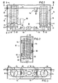
- the in Fig. 1 shown plasma reactor 10 for flexible strand material 12 has a disposed inside a container 14 reactor chamber 16 for plasma processing.
- a box-shaped rigid container wall 18 of the container 14 has at its one end a passage 20 for the entry of the strand material 12 in the reactor chamber 16 and at its other end a passage 22 for the exit of the strand material 12 from the reactor chamber 16th
- a first roller 24 and a second roller 26 are arranged as guide elements for the strand material 12.
- the rollers 24,26 have mutually parallel axes of rotation 28,30, which are spaced apart and extend perpendicular to a bottom wall 32 of the container 14.
- Each of the rollers 24,26 has eight translator elements 34, which are elongated, rod-shaped strips.
- the converter elements 34 of the first roller 24 are guided displaceably on a first base body 36 in the direction of the axis of rotation 28. On their outer side they each have a driver surface 38 for the strand material 12, which either follows exactly the course of the cylinder jacket surface of the roller 24 or has an outward curvature of strong clogging.
- the converter elements 34 are provided with a spherical standing surface 40 on a swashplate 42, which is tiltable and rotationally fixed about the axis of rotation 28 in the reactor chamber 16.
- the converter elements 34 of the first roller 24 are driven in rotation by the base body 36 in the direction of the arrow A, so that they are lowered during a rotation about the rotation axis 28 and raised again.
- the swash plate 42 thus forms together with the base body 36 and the Umsetzermaschinen 34 a screw jack.
- an adjusting mechanism 44 which has a hub 48 carrying an eccentrically arranged cam 46.
- the hub 48 is rotatable via a drive linkage 50, which is driven by a motor 51, such that the cam 46 about the rotation axis 28th the first roller 24 is running while the swash plate 42 is raised or lowered on one side.
- the second roller 26 has a structure corresponding to the first roller 24. It differs from the first roller 24 only in that the inclination of the swash plate 52 of the second roller 26 is opposite to the inclination of the swash plate 42 of the first roller 24 with respect to the axes of rotation 28,30.
- the strand material 12 being processed in the reactor space 16 travels from the passage 20 past the first roller 24 to the second roller 26.
- the strand material first abuts a translator element 34 which is furthest in it is raised position.
- the strand material wraps around the second roller 26 with a wrap angle of 180 °, wherein it rests on three or four further converter elements 34, depending on the rotational position of the roller 26.
- the strand material travels back to the first roller 24 abutting against a translator element which is at its highest position.
- the strand material 12 is again depending on the rotational position of the roller 24 to three or four converter elements 34, which are each at a lower level than the previous converter element on this roller 24. From the first Roller 24 then runs the flexible strand material 12 back to the second roller 26, the strand material on its way from the passage 20 for the entrance to the passage 22 for the outlet back and forth several times between the rollers in staggered turns back and forth.
- the strand material encloses the two rollers 24,26 only on the side at which the Umsetzeriana 34 perform on their way around the respective axis of rotation 28,30 a downward movement, the strand material 12 from the overhead passage 20 at the inlet side to the underlying passage 22 guided on the outlet side. Their upward movement lead the Umsetzeriana 34 substantially in a region in which no strand material 12 abuts against them.
- the conversion elements 34 can also be operated in a horizontal position when they are positively guided.
- the rollers can also be arranged one above the other.
- the container 14 is connected to a suction source, not shown, which generates a vacuum in the reactor chamber 16.
- a gas inlet device not shown, is provided, can be passed with the inert and / or reaction gases in the reactor space.
- the arrangement of the gas inlet device and the suction source is such that the plasma reactor is operable as a countercurrent reactor, as a cross-flow reactor and / or as a cross-flow reactor.
- a plurality of electrode pairs 54, 56, 58, 60 are provided, wherein the electrodes of the electrode pairs 54, 56, 58, 60 are each arranged at a distance from one another such that the strand material 12 is between them can be passed.
- the electrodes each generate a plasma which encloses strand material sections 62 of a plurality of turns of the strand material 12 staggered in the axial direction.
- the electrode pairs 54,56,58,60 are arranged in the axial direction of the rollers 24,26, at different heights. They are located between the rollers 24,26 in the range of free conveyor sections of the strand material 12, in areas where the strand material 12 is not Sakbergert. In this case, they are arranged both at the connecting region of the rollers 24, 26 in which the strand material runs from the first roller 24 to the second roller 26 as well as in the connecting region in which the strand material extends from the second roller 26 to the first roller 24 , The distance in the axial direction of the rollers 24, 26 between the electrode pairs 54, 56, 58, 60 arranged in descending order is the same in each case.
- the plasmas processing the strand material 12 may also be replaced by other plasma sources, e.g. Microwave sources are generated.
- the reactor In order to process with the plasma reactor 10, for example sheep wool sliver, the reactor is first charged in a preparatory step, wherein the strand material is guided in mutually offset turns around the rollers 24,26 until the height difference between the passage 20 and the passage 22 is overcome. After evacuating the reactor chamber 16 and setting a desired gas atmosphere, a plasma is in each case ignited by means of a suitable current source between the electrode pairs 54, 56, 58, 60. The strand material 12 is passed through the passage 20 continuously into the reactor chamber 16 and continuously pulled out through the passage 20 therethrough. The first and second rollers 24,26 are driven at a peripheral speed, which corresponds to the feeding and drawing speed of the strand material 12.
- a plasma is in each case ignited by means of a suitable current source between the electrode pairs 54, 56, 58, 60.
- the strand material 12 is passed through the passage 20 continuously into the reactor chamber 16 and continuously pulled out through the passage 20 therethrough.
- the first and second rollers 24,26 are driven at a peripheral speed, which
- the processing time can be adjusted at a given peripheral speed of the rollers 24,26 by the number of turns of the strand material 12 in the plasma reactor 10. If a small number of turns is required for a short machining time, the pitch of the swash plates 42, 52 is increased with the motor 51. If a long processing time is desired, the strand material 12 is laid around the rollers 24, 26 in a large number of turns. In this case, the inclination of the swash plates 42,52 is reduced so that they are almost perpendicular to the axes of rotation 28,30.
- the plasma reactor 10 is used primarily for degreasing and for removing dandruff. However, it is also possible to use the plasma reactor 10 for surface treatment of wire or plastics and synthetic pulps, e.g. for plasma polymerization, for activation of Kevlar fibers, for metallization or for plasma etching.
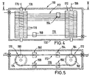
- the plasma reactor 110 according to the second embodiment in FIGS FIGS. 4 and 5 differs from the plasma reactor 10 according to the first embodiment only by the configuration of the first roller 170 and the second roller 172. Portions of the plasma reactor 110 according to the second embodiment, which correspond to parts of the plasma reactor 10 according to the first embodiment, are therefore provided with reference numerals, which are increased by 100 compared to the first embodiment.
- the first roller 170 has a roller body 174, on the outer, substantially cylindrical surface of which a multiplicity of parallel running grooves 178 concentric to the axis 176 of the roller body are formed. In the grooves 178, the strand material 112 is guided. In order to transfer the strand material 112 from a groove 178 into an underlying groove 178, a conversion strip 180 is inserted into the roll body 174, which rotates together with the roll body 174 and displaces the strand material 112 in the axial direction.
- the second roller 172 is constructed in accordance with the first roller 170 and has a converter bar 184 embedded in a roller body 182.
- the two roller bodies 174, 182 are rotated at a matching speed, wherein the converter bars 180, 84 always have the same rotational position with respect to a plane connecting the axes 176 of the first roller 170 with the axis 186 of the second roller 172.
- the two Umsetzermannn 180,184 are simultaneously moved axially in response to the rotational position of the roller body 174,182, so that a coordinated material feed of the strand material in the direction of the axes 176,186 takes place.
Landscapes
- Engineering & Computer Science (AREA)
- Physics & Mathematics (AREA)
- Plasma & Fusion (AREA)
- Textile Engineering (AREA)
- Chemical & Material Sciences (AREA)
- Analytical Chemistry (AREA)
- Materials Engineering (AREA)
- Treatment Of Fiber Materials (AREA)
- Transition And Organic Metals Composition Catalysts For Addition Polymerization (AREA)
- Chemical Or Physical Treatment Of Fibers (AREA)
Claims (8)
- Réacteur à plasma pour du matériau en boudin (12) flexible, comprenant des orifices (20, 22) pour l'entrée et la sortie du matériau en boudin (12) dans la chambre (16) du réacteur, des sources de plasma disposées dans la chambre (16) du réacteur, pour la génération d'un plasma, ainsi qu'un dispositif de guidage disposé dans la chambre (16) du réacteur, à l'aide duquel le matériau en boudin (12) peut être dirigé le long d'un trajet de traitement,
le dispositif de guidage présentant au moins deux rouleaux (24, 26 ; 170, 172) d'axes parallèles, entraînés en rotation de façon synchrone, autour desquels le matériau en boudin (12) circule en plusieurs spires décalées axialement l'une par rapport à l'autre, et les sources de plasma étant positionnées de telle manière que le plasma, qu'elles génèrent, touche simultanément des tronçons (62) d'au moins deux spires décalées axialement l'une par rapport à l'autre,
caractérisé
en ce que sur chacun des rouleaux est disposé au moins un organe de changement de place (34 ; 180, 184) déplaçable, de façon commandée, dans la direction axiale du rouleau, les organes de changement de place (34 ; 180, 184) transportant alors le matériau en boudin (12 ; 112) dans la direction de l'axe des rouleaux (24, 26 ; 170, 172), en fonction de la position angulaire des rouleaux (24, 26 ; 170, 172), et étant réglables, en ce qui concerne leur course, par un mécanisme de réglage (44) commun. - Réacteur à plasma selon la revendication 1, caractérisé en ce que chacun des rouleaux (24, 26) présente plusieurs organes de changement de place (34) allongés, disposés parallèlement l'un à l'autre et aux axes (28, 30) des rouleaux (24, 26), les organes de changement de place (34) de chaque rouleau (24, 26) pouvant être abaissés cycliquement par l'intermédiaire d'un système élévateur.
- Réacteur à plasma selon la revendication 2, caractérisé en ce que le système élévateur présente un disque oblique (42, 52) fixe, et en ce que les organes de changement de place (34) sont entraînés en rotation autour de l'axe de rotation (28, 30) du rouleau (24, 26) considéré, en circulant sur le disque oblique (42, 52).
- Réacteur à plasma selon la revendication 3, caractérisé en ce que l'inclinaison du disque oblique (42, 52), par rapport à l'axe de rotation (28, 30) du rouleau (24, 26) considéré, est réglable.
- Réacteur à plasma selon l'une des revendications 1 à 4, caractérisé en ce que les sources de plasma sont des électrodes (54, 56, 58, 60).
- Réacteur à plasma selon la revendication 5, caractérisé en ce que les électrodes (54, 56, 58, 60) sont disposées entre les rouleaux (24, 26), dans la région de longueurs libres de transport du matériau en boudin (12), et, par paires respectives, génèrent entre elles un plasma, à travers lequel le matériau en boudin (12) est dirigé.
- Réacteur à plasma selon l'une des revendications 1 à 4, caractérisé en ce que les sources de plasma sont des émetteurs de rayonnement haute fréquence.
- Réacteur à plasma selon la revendication 1, caractérisé en ce que les rouleaux (170, 172) présentent chacun plusieurs gorges de guidage (178) orientées parallèlement l'une à l'autre, qui sont situées dans des plans perpendiculaires aux axes de rotation (176, 186) respectifs des rouleaux (170, 172), et en ce que les organes de changement de place (180, 184) font passer le matériau en boudin (112) du plan d'une gorge de guidage (178) dans le plan d'une gorge de guidage (178) située en dessous.
Applications Claiming Priority (2)
| Application Number | Priority Date | Filing Date | Title |
|---|---|---|---|
| DE29600991U | 1996-01-20 | ||
| DE29600991U DE29600991U1 (de) | 1996-01-20 | 1996-01-20 | Plasmareaktor |
Publications (3)
| Publication Number | Publication Date |
|---|---|
| EP0785569A2 EP0785569A2 (fr) | 1997-07-23 |
| EP0785569A3 EP0785569A3 (fr) | 2005-07-20 |
| EP0785569B1 true EP0785569B1 (fr) | 2008-02-13 |
Family
ID=8018339
Family Applications (1)
| Application Number | Title | Priority Date | Filing Date |
|---|---|---|---|
| EP96120621A Expired - Lifetime EP0785569B1 (fr) | 1996-01-20 | 1996-12-20 | Réacteur à plasma |
Country Status (5)
| Country | Link |
|---|---|
| US (1) | US5972160A (fr) |
| EP (1) | EP0785569B1 (fr) |
| DE (2) | DE29600991U1 (fr) |
| ES (1) | ES2302334T3 (fr) |
| PT (1) | PT785569E (fr) |
Families Citing this family (19)
| Publication number | Priority date | Publication date | Assignee | Title |
|---|---|---|---|---|
| DE19616776C1 (de) * | 1996-04-26 | 1997-09-18 | Bayer Ag | Verfahren zur Antifilz-Ausrüstung von Wollmaterial mit Hilfe einer Niedertemperatur-Plasmabehandlung |
| US6358481B1 (en) | 2000-11-14 | 2002-03-19 | Lockheed Martin Corporation | Electrically safe dual electrode plasma treatment chamber system |
| KR100405172B1 (ko) * | 2001-07-24 | 2003-11-12 | 주식회사 선익시스템 | 플라즈마 표면 처리장치 및 이를 이용한 플라즈마 표면처리방법 |
| US20040076543A1 (en) * | 2002-03-18 | 2004-04-22 | Sokolowski Asaf Zeev | System and method for decontamination and sterilization of harmful chemical and biological materials |
| WO2005095668A1 (fr) * | 2004-03-31 | 2005-10-13 | Pirelli Tyre S.P.A. | Procede et appareil pour la production d'un fil metallique revetu d'une couche d'alliage metallique |
| KR100750654B1 (ko) * | 2006-09-15 | 2007-08-20 | 한국전기연구원 | 장선 테이프 증착장치 |
| EP2099964B1 (fr) * | 2006-11-13 | 2018-02-14 | Serge Ferrari Tersuisse AG | Objet filiforme enrobé à conductivité électrique améliorée et/ou à réflexion optique améliorée, et dispositif et procédé de traitement de surface d'un objet filiforme |
| JP2010081673A (ja) * | 2008-09-24 | 2010-04-08 | Sanyo Electric Co Ltd | バッテリシステム及びバッテリパック |
| US8460746B2 (en) * | 2009-09-09 | 2013-06-11 | Cochlear Limited | Method of forming insulated conductive element having a substantially continuous barrier layer formed via relative motion during deposition |
| US20110056729A1 (en) * | 2009-09-09 | 2011-03-10 | Cochlear Limited | Insulated conductive element having a substantially continuous barrier layer formed through continuous vapor deposition |
| US8545926B2 (en) * | 2009-09-09 | 2013-10-01 | Cochlear Limited | Method of forming insulated conductive element having substantially continuously coated sections separated by uncoated gaps |
| US8726492B2 (en) * | 2009-09-09 | 2014-05-20 | Cochlear Limited | Insulated conductive element having a substantially continuous barrier layer formed through multiple coatings |
| US8632860B2 (en) * | 2011-11-02 | 2014-01-21 | Sheila Shahidi | Method of preparation of multifunctional technical textile by plasma-treatment |
| CH707323A2 (de) * | 2012-12-13 | 2014-06-13 | Empa Eidgenössische Materialprüfungs Und Forschungsanstalt | Verfahren und Vorrichtung zur Beschichtung von Textilfasern mittels Plasmabehandlung. |
| RU2566259C1 (ru) * | 2014-08-28 | 2015-10-20 | Закрытое акционерное общество Научно-производственное объединение "Ударно-волновые технологии" | Устройство для ударно-волновой обработки волокнистых материалов |
| EP3449033A1 (fr) | 2015-11-05 | 2019-03-06 | Bühler Alzenau GmbH | Dispositif et procédé de dépôt sous vide |
| CN113413895B (zh) * | 2021-07-09 | 2022-03-29 | 苏州道一至诚纳米材料技术有限公司 | 薄膜催化剂的生产设备及生产方法 |
| CN113639541B (zh) * | 2021-08-23 | 2022-11-15 | 烟台锐泽化学品有限公司 | 一种碳纤维材料生产用干燥方法 |
| US12594690B2 (en) * | 2022-11-09 | 2026-04-07 | General Electric Company | Methods and apparatus for coating fibers |
Family Cites Families (26)
| Publication number | Priority date | Publication date | Assignee | Title |
|---|---|---|---|---|
| US2155324A (en) * | 1937-04-09 | 1939-04-18 | American Enka Corp | Manufacture of artificial silk |
| US2267402A (en) * | 1940-12-12 | 1941-12-23 | Ind Rayon Corp | Apparatus for manipulating thread or the like |
| US2567233A (en) * | 1946-09-19 | 1951-09-11 | Minnesota Mining & Mfg | Reflex-reflective sheet material useful for protective garments and the like |
| NL67929C (fr) * | 1947-07-02 | |||
| US2614313A (en) * | 1948-07-21 | 1952-10-21 | Shell Dev | Adjustable self-transporting thread store reel |
| US2622860A (en) * | 1949-05-10 | 1952-12-23 | United States Steel Corp | Apparatus for continuously processing strands |
| US2532562A (en) * | 1949-09-12 | 1950-12-05 | Carnegie Illinois Steel Corp | Continuous strand helical conveying and heating apparatus |
| GB798483A (en) * | 1954-07-10 | 1958-07-23 | Kalle & Co Ag | Traversing reel |
| CS151038B2 (fr) * | 1969-08-19 | 1973-09-17 | ||
| DE2063355C3 (de) * | 1970-12-23 | 1974-01-31 | Hans 5550 Bernkastel-Kues Stang | Trockenmaschine zum Krumpfen oder Ausrecken von laufenden Bändern |
| US3884787A (en) * | 1973-01-12 | 1975-05-20 | Coulter Information Systems | Sputtering method for thin film deposition on a substrate |
| US4013539A (en) * | 1973-01-12 | 1977-03-22 | Coulter Information Systems, Inc. | Thin film deposition apparatus |
| US3959104A (en) * | 1974-09-30 | 1976-05-25 | Surface Activation Corporation | Electrode structure for generating electrical discharge plasma |
| US4065101A (en) * | 1976-10-07 | 1977-12-27 | Korkut Mehmet D | Torsion spool |
| JPS5718737A (en) * | 1980-06-21 | 1982-01-30 | Shin Etsu Chem Co Ltd | Apparatus for continuous plasma treatment |
| JPS6011150B2 (ja) * | 1982-01-06 | 1985-03-23 | 株式会社山東鉄工所 | 布帛の低温プラズマ連続処理装置 |
| US4457145A (en) * | 1983-03-29 | 1984-07-03 | Sando Iron Works Co., Ltd. | Apparatus for treating a textile product continuously with the use of low-temperature plasma |
| FR2590808B1 (fr) * | 1985-12-04 | 1989-09-15 | Canon Kk | Dispositif de soufflage de particules fines |
| US4829189A (en) * | 1986-07-18 | 1989-05-09 | Sando Iron Works Co., Ltd. | Apparatus for low-temperature plasma treatment of sheet material |
| US4728406A (en) * | 1986-08-18 | 1988-03-01 | Energy Conversion Devices, Inc. | Method for plasma - coating a semiconductor body |
| DE4117332C2 (de) * | 1991-05-31 | 1995-11-23 | Ivanovskij Ni Skij Eksperiment | Verfahren zur Behandlung von laufendem Substrat mit Hilfe eines elektrischen Entladungsplasmas und Vorrichtung zu dessen Durchführung |
| ES2081512T3 (es) * | 1992-03-31 | 1996-03-16 | Mag Masch App | Dispositivo de traccion para alambre. |
| IT1261918B (it) * | 1993-06-11 | 1996-06-04 | Cetev Cent Tecnolog Vuoto | Struttura per deposizione reattiva di metalli in impianti da vuoto continui e relativo processo. |
| DE4333825C1 (de) * | 1993-09-28 | 1995-02-23 | Mat Gmbh | Vorrichtung zum Beschichten von langgestreckten biegsamen Erzeugnissen |
| US5439736A (en) * | 1994-01-21 | 1995-08-08 | Neomecs Incorporated | Gas plasma polymerized permselective membrane |
| JPH0863746A (ja) * | 1994-08-24 | 1996-03-08 | Fuji Photo Film Co Ltd | 磁気記録媒体の製造方法及び装置 |
-
1996
- 1996-01-20 DE DE29600991U patent/DE29600991U1/de not_active Expired - Lifetime
- 1996-12-20 ES ES96120621T patent/ES2302334T3/es not_active Expired - Lifetime
- 1996-12-20 EP EP96120621A patent/EP0785569B1/fr not_active Expired - Lifetime
- 1996-12-20 DE DE59611459T patent/DE59611459D1/de not_active Expired - Lifetime
- 1996-12-20 PT PT96120621T patent/PT785569E/pt unknown
- 1996-12-23 US US08/771,697 patent/US5972160A/en not_active Expired - Lifetime
Also Published As
| Publication number | Publication date |
|---|---|
| EP0785569A3 (fr) | 2005-07-20 |
| US5972160A (en) | 1999-10-26 |
| PT785569E (pt) | 2008-05-07 |
| DE29600991U1 (de) | 1997-05-22 |
| ES2302334T3 (es) | 2008-07-01 |
| DE59611459D1 (de) | 2008-03-27 |
| EP0785569A2 (fr) | 1997-07-23 |
Similar Documents
| Publication | Publication Date | Title |
|---|---|---|
| EP0785569B1 (fr) | Réacteur à plasma | |
| DE69516868T2 (de) | Vorrichtung zum einbringen von rillen in zylindrischen oberflächen | |
| CH673605A5 (fr) | ||
| DE2755516A1 (de) | Verfahren und maschine zur kontinuierlichen herstellung einer unverwebten netzstruktur | |
| EP3029197B1 (fr) | Élingue ronde et procede et dispositif de fabrication | |
| EP0365826B2 (fr) | Procédé et dispositif pour la production de panneaux à base de fibres minérales | |
| DD284664A5 (de) | Verfahren und vorrichtung zur aufbereitung von glasplatten durch ausbauchen und haerten | |
| DE69413804T2 (de) | Vorrichtung und verfahren zur gleichmässigen bestrahlung eines stranges | |
| DE69313957T2 (de) | Vorrichtung zum Kräuseln eines Faserstranges und zum Aufbringen von Finish auf den Faserstrang | |
| CH634119A5 (de) | Verfahren und vorrichtung zur kontinuierlichen herstellung von strangfoermigem gut durch verseilung von formstraengen. | |
| EP0289845B1 (fr) | Dispositif pour transporter et retourner en continu des pièces | |
| DE2642173C2 (de) | Verfahren und Vorrichtung zur Behandlung von eine Kammer durchlaufenden Elementen mittels Gasen | |
| EP0607891B1 (fr) | Installation pour rétrécir étirer, sécher, apprêter, teindre, alimenter ou autres une matière textile en déplacement telle que bandes ou fils | |
| DE2058026A1 (de) | Vorrichtung zum Biegen der Strebenschlange von Gittertraegern | |
| EP0012330B1 (fr) | Dispositif pour le guidage et le déplacement de produits bobinables dans un champ d'irradiation électronique | |
| DE2441371C2 (de) | Vorrichtung zum Vernetzen einer mit Polyolefin isolierten Kabelseele | |
| EP0631993A1 (fr) | Procédé et appareil à pousser des objets de verre d'une courroie transporteuse sur une autre | |
| EP1449958B1 (fr) | Dispositif pour traiter en particulier pour traiter par dépression, la toile de fabrication ou le feutre d'une machine à papier | |
| DE2642118C2 (de) | Streckwerk für Natur- und/oder Kunstfasern | |
| WO2019114974A1 (fr) | Dispositif de nettoyage à jet de gaz | |
| DE8133321U1 (de) | Vorrichtung zum schleifenförmigen Biegen eines fortlaufenden Drahtes | |
| DE1813179A1 (de) | Mehrfachrollkopf | |
| CH658416A5 (de) | Vorrichtung zum schleifenfoermigen biegen eines fortlaufenden drahtes. | |
| DE2726234B2 (de) | Vorrichtung zur Übertragung von Zugkräften auf strangförmige Werkstücke | |
| DE3825883A1 (de) | Vorrichtung zum formen von faserstoffen |
Legal Events
| Date | Code | Title | Description |
|---|---|---|---|
| PUAI | Public reference made under article 153(3) epc to a published international application that has entered the european phase |
Free format text: ORIGINAL CODE: 0009012 |
|
| AK | Designated contracting states |
Kind code of ref document: A2 Designated state(s): DE ES FR GB IT PT |
|
| AX | Request for extension of the european patent |
Free format text: AL PAYMENT 961220;LT PAYMENT 961220;LV PAYMENT 961220;RO PAYMENT 961220;SI PAYMENT 961220 |
|
| PUAL | Search report despatched |
Free format text: ORIGINAL CODE: 0009013 |
|
| AK | Designated contracting states |
Kind code of ref document: A3 Designated state(s): DE ES FR GB IT PT |
|
| AX | Request for extension of the european patent |
Extension state: AL LT LV RO SI |
|
| RIC1 | Information provided on ipc code assigned before grant |
Ipc: 7C 23C 16/50 B Ipc: 7H 01J 37/317 B Ipc: 7H 01J 37/32 A |
|
| 17P | Request for examination filed |
Effective date: 20051026 |
|
| GRAP | Despatch of communication of intention to grant a patent |
Free format text: ORIGINAL CODE: EPIDOSNIGR1 |
|
| GRAS | Grant fee paid |
Free format text: ORIGINAL CODE: EPIDOSNIGR3 |
|
| GRAA | (expected) grant |
Free format text: ORIGINAL CODE: 0009210 |
|
| AK | Designated contracting states |
Kind code of ref document: B1 Designated state(s): DE ES FR GB IT PT |
|
| AX | Request for extension of the european patent |
Extension state: AL LT LV RO SI |
|
| REG | Reference to a national code |
Ref country code: GB Ref legal event code: FG4D Free format text: NOT ENGLISH |
|
| REF | Corresponds to: |
Ref document number: 59611459 Country of ref document: DE Date of ref document: 20080327 Kind code of ref document: P |
|
| REG | Reference to a national code |
Ref country code: PT Ref legal event code: SC4A Free format text: AVAILABILITY OF NATIONAL TRANSLATION Effective date: 20080423 |
|
| REG | Reference to a national code |
Ref country code: ES Ref legal event code: FG2A Ref document number: 2302334 Country of ref document: ES Kind code of ref document: T3 |
|
| ET | Fr: translation filed | ||
| PLBE | No opposition filed within time limit |
Free format text: ORIGINAL CODE: 0009261 |
|
| STAA | Information on the status of an ep patent application or granted ep patent |
Free format text: STATUS: NO OPPOSITION FILED WITHIN TIME LIMIT |
|
| 26N | No opposition filed |
Effective date: 20081114 |
|
| REG | Reference to a national code |
Ref country code: FR Ref legal event code: PLFP Year of fee payment: 20 |
|
| PGFP | Annual fee paid to national office [announced via postgrant information from national office to epo] |
Ref country code: GB Payment date: 20151221 Year of fee payment: 20 |
|
| PGFP | Annual fee paid to national office [announced via postgrant information from national office to epo] |
Ref country code: PT Payment date: 20151207 Year of fee payment: 20 Ref country code: FR Payment date: 20151218 Year of fee payment: 20 Ref country code: ES Payment date: 20151218 Year of fee payment: 20 |
|
| PGFP | Annual fee paid to national office [announced via postgrant information from national office to epo] |
Ref country code: DE Payment date: 20151221 Year of fee payment: 20 |
|
| PGFP | Annual fee paid to national office [announced via postgrant information from national office to epo] |
Ref country code: IT Payment date: 20151222 Year of fee payment: 20 |
|
| REG | Reference to a national code |
Ref country code: DE Ref legal event code: R071 Ref document number: 59611459 Country of ref document: DE |
|
| REG | Reference to a national code |
Ref country code: GB Ref legal event code: PE20 Expiry date: 20161219 |
|
| PG25 | Lapsed in a contracting state [announced via postgrant information from national office to epo] |
Ref country code: GB Free format text: LAPSE BECAUSE OF EXPIRATION OF PROTECTION Effective date: 20161219 |
|
| PG25 | Lapsed in a contracting state [announced via postgrant information from national office to epo] |
Ref country code: PT Free format text: LAPSE BECAUSE OF EXPIRATION OF PROTECTION Effective date: 20161228 |
|
| PG25 | Lapsed in a contracting state [announced via postgrant information from national office to epo] |
Ref country code: ES Free format text: LAPSE BECAUSE OF EXPIRATION OF PROTECTION Effective date: 20161221 |