EP0785492B1 - Verfahren zum schrittbetrieb eines roboters - Google Patents
Verfahren zum schrittbetrieb eines roboters Download PDFInfo
- Publication number
- EP0785492B1 EP0785492B1 EP96926608A EP96926608A EP0785492B1 EP 0785492 B1 EP0785492 B1 EP 0785492B1 EP 96926608 A EP96926608 A EP 96926608A EP 96926608 A EP96926608 A EP 96926608A EP 0785492 B1 EP0785492 B1 EP 0785492B1
- Authority
- EP
- European Patent Office
- Prior art keywords
- axis
- jog
- coordinate system
- robot
- tool
- Prior art date
- Legal status (The legal status is an assumption and is not a legal conclusion. Google has not performed a legal analysis and makes no representation as to the accuracy of the status listed.)
- Expired - Lifetime
Links
Images


Classifications
-
- G—PHYSICS
- G05—CONTROLLING; REGULATING
- G05B—CONTROL OR REGULATING SYSTEMS IN GENERAL; FUNCTIONAL ELEMENTS OF SUCH SYSTEMS; MONITORING OR TESTING ARRANGEMENTS FOR SUCH SYSTEMS OR ELEMENTS
- G05B19/00—Programme-control systems
- G05B19/02—Programme-control systems electric
- G05B19/42—Recording and playback systems, i.e. in which the programme is recorded from a cycle of operations, e.g. the cycle of operations being manually controlled, after which this record is played back on the same machine
- G05B19/425—Teaching successive positions by numerical control, i.e. commands being entered to control the positioning servo of the tool head or end effector
-
- G—PHYSICS
- G05—CONTROLLING; REGULATING
- G05B—CONTROL OR REGULATING SYSTEMS IN GENERAL; FUNCTIONAL ELEMENTS OF SUCH SYSTEMS; MONITORING OR TESTING ARRANGEMENTS FOR SUCH SYSTEMS OR ELEMENTS
- G05B2219/00—Program-control systems
- G05B2219/30—Nc systems
- G05B2219/50—Machine tool, machine tool null till machine tool work handling
- G05B2219/50048—Jogging
-
- G—PHYSICS
- G05—CONTROLLING; REGULATING
- G05B—CONTROL OR REGULATING SYSTEMS IN GENERAL; FUNCTIONAL ELEMENTS OF SUCH SYSTEMS; MONITORING OR TESTING ARRANGEMENTS FOR SUCH SYSTEMS OR ELEMENTS
- G05B2219/00—Program-control systems
- G05B2219/30—Nc systems
- G05B2219/50—Machine tool, machine tool null till machine tool work handling
- G05B2219/50356—Tool perpendicular, normal to 3-D surface
Definitions
- the present invention relates to a jog operation method for an industrial robot (hereinafter referred to as a "robot") and, more particularly, to a jog operation method which is designed to perform a jog-feeding operation conforming to a coordinate system having coordinate axes which coincide with the moving directions of a robot.
- the present invention can be effectively applied when an attitude (attitude of a welding torch, a sealing gun, a spot gun, or the like) is to be taught to a welding robot or a sealing robot.
- the latter jog operation method comprises a base (world) coordinate system jog, a user coordinate system jog, a tool coordinate system jog, individual axes jog, and the like. These methods are selectively used for various applications.
- the tool coordinate system jog is characterized by that jog operation by translational/rotational moving direction during a jog operation can be specified according to a tool coordinate system defined together with a tool such as a welding torch, a sealing gun, a spot gun, or a hand which are to be mounted on the distal end of the robot. For this reason, this tool coordinate system jog is relatively frequently used in an application such as arc welding or sealing.
- a tool coordinate system such that a distal end 2 of a welding torch (hereinafter referred to as "torch") 1 is defined as an origin, a torch direction is defined as a Z axis, and a direction which frequently corresponds to a torch front is defined as an X axis.
- torch front means a torch surface which faces a welding line direction (advancing direction of welding) 3.
- the relationship between a jog operation key and the moving direction of the robot can be sensed with greater ease in this way.
- an operator not only can be conscious of a jog key operation for moving around an ⁇ X axis in correspondence with rotational movement around the welding line direction 3, but also can be conscious of rotational movement around an axis which is vertical to the welding line direction 3, or vertical to the coordinate axis corresponding to the axial direction of the tool, relating to a jog key operation for moving around a ⁇ Y axis.
- a work angle and a travel angle are used as quantities for describing torch attitudes to be adjusted as described above.
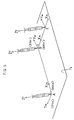
- Fig. 2 is a view for explaining a work angle and a travel angle on an arc welding robot, and shows the relationship among a welding line, a reference surface, a work angle, a travel angle with reference to linear welding paths A and B.
- a reference surface ⁇ 0 is used as a reference together with the welding line direction (direction of A - B) 3 when the work angle is defined.
- a work surface representing a work portion in which the welding path A-B is present is selected as the reference surface ⁇ 0.
- Reference symbol ⁇ n> denotes a normal vector representing the direction of the reference surface ⁇ 0
- reference symbol ⁇ 1 denotes a surface which is vertical to the reference surface ⁇ 0 with respect to the path A-B being a cross line.
- the reference surface ⁇ 0 is used only to define the work angle.
- an angle between the plane ⁇ and the reference plane ⁇ 0 is a work angle ⁇ .
- a vertical (ie perpendicular) line g extending from a tool center point 2, and vertical to the welding line A-B is set on the plane ⁇
- an angle between a straight line representing the direction (Z-axis direction of the tool coordinate system) of the torch 1 and the straight line g is a travel angle ⁇ .
- the work angle ⁇ is an angle around the welding line A-B
- the travel angle ⁇ is an angle around the vertical line g extending from the welding line A-B on a reference plane (work surface) ⁇ 0.
- a torch attitude to be defined by a work angle and a travel angle must be taught accurately. For this reason, in an actual position teaching operation, a careful operation must be performed to adjust the work angle and the travel angle at each teaching point.
- the work angle can be adjusted by a jog operation around the X axis and adjustment of the travel angle, by the jog operation around Y-axis.
- the jog operation based on a conventional tool coordinate system is carried out according to a coordinate system corresponding to the attitude of a wrist of the robot, so that it is effective in teaching a path position of a robot which has a wrist to which a tool (a welding torch, a sealing gun, a spot gun, a hand, or the like) is attached.
- a tool a welding torch, a sealing gun, a spot gun, a hand, or the like
- the conventional jog operation method provides an effective means when an attitude of a tool relative to a work has to be correctly taught.
- a jog operation method for a robot for causing the robot to execute jog movement by using manual input means connected to a robot controller, comprising the steps of: setting a path-tool coordinate system by calculating data representing the direction of a first coordinate axis which coincides with a movement path direction and data representing the direction of a second coordinate axis which is perpendicular to both the first coordinate axis and a coordinate axis corresponding to an axial direction of a tool, based on the positional data for the movement along the path, for the robot whose tool coordinate system has been set, and storing these calculated data; and receiving an output from said manual input means to cause said robot to perform at least one of rotational jog movement around the first coordinate axis, translational jog feeding movement in the first coordinate axis direction, rotational jog movement around the second coordinate axis, and translational jog movement in the second coordinate axis direction.
- a jog operation system according to a second aspect of the present invention is defined in attached claim 7.
- the present invention it is possible to perform a jog operation conforming to a coordinate system having the coordinate axis which coincides with the path direction and the coordinate axis which is perpendicular to the path direction and the axial center of the tool, so that a tool attitude such as a work angle or a travel angle can be adjusted easily by selecting a coordinate axis and operating a jog key provided on an operation panel.
- the present invention is characterized in that a new coordinate system, i.e., a "path-tool coordinate system" is set for each straight path.
- a new coordinate system i.e., a "path-tool coordinate system” is set for each straight path.
- the coordinate system will be described below with reference to Fig. 5.
- the X axis of the path-tool coordinate system coincides with the path A-B
- the Y axis is vertical to the X axis and also vertical to the axis of a tool placed at a start point A of the path
- the Z axis coincides with the axis (Z axis of the tool coordinate system) of the tool.
- the X axis, Y axis, and Z axis are represented by XAB, YAB, and Zf, respectively.
- the X axis of the path-tool coordinate system coincides with the path B-C; the Y axis is in a direction which is vertical to the X axis and vertical to the axis of a tool placed at a start point B of the path; and the Z axis coincides with the axis (Z axis of the tool coordinate system) of the tool.
- the path-tool coordinate system for the path B-C, the X axis, Y axis, and Z axis are represented by XBC, YBC, and Zf, respectively.
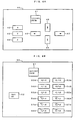
- a robot controller 10 has a central processing unit 11 (hereinafter referred to as a CPU). Connected to the CPU 11 through a bus 19 are memory 12 constituted of a ROM, a memory 13 constituted of a RAM, a nonvolatile memory 14, an input/output device 15 serving as an interface between the CPU 11 and an external device including a power source (not shown) of a welding torch, an interface 16 for a teaching operation panel 30, and a robot axis control section 17 which controls the operation of each axis of a robot mechanism section 20 through a servo circuit 18.
- a program for controlling the entire system including the robot controller 10 itself is stored in the ROM 12.
- the RAM 13 is used to temporarily store the data for processings to be performed by the CPU 11.
- the nonvolatile memory 14 stores not only operation program data of the robot and various set values relating to the operations of the various sections of the system but also a program relating to setting of a jog coordinate system (to be described later) and jog feeding based thereon and other various data.
- the teaching operation panel 30 connected to the interface 16 has a jog operation section 40 which can output a command to the robot controller 10 by a manual input.
- the jog operation section 40 has a jog operation function using a conventional scheme and another function for making the CPU 11 execute a processing (to be described later) to output a command for jog operation conforming to a path-tool coordinate system.
- a coordinate system key 41 is for selecting a conformable coordinate system for a jog operation.
- the coordinate system key 41 can select not only a conformable coordinate system (three-dimensional orthogonal coordinate system such as a base coordinate system, a user coordinate system, or a tool coordinate system) in a jog operation using a conventional scheme, but also a "path-tool coordinate system".
- Keys 42, 43, and 44 are jog keys which are used for both jog operation using a conventional scheme and jog operation according to the present invention, and output commands for jog movement relating to the X axis, Y axis, and Z axis of the coordinate system selected by the coordinate system key 41, respectively.
- Shift keys 46 to 49 are keys each of which is to be pressed together with one of the keys 42, 43, and 44 to shift a function mode.
- the jog key 44 related to the Z axis maintains the same function as that available when the "tool coordinate system" is selected.
- the robot upon completion of adjustment and teaching of position with respect to the position B, the robot is moved to the position C, and adjustment with respect to the position C and positional teaching are performed. Since the position C is the end point, the position C is regarded as a point belonging the path B-C. Therefore, the function of each key in a path-tool jog operation is the same as the function in the case of adjustment with respect to the position B.
- a coordinate system key 51 is for selecting a coordinate system to be conformed to in a jog operation.
- the coordinate system key 51 can select not only a coordinate system to be conformed to in a jog operation according to a conventional way (a three-dimensional orthogonal coordinate system such as a base coordinate system, a user coordinate system, or a tool coordinate system and individual-axis coordinate system), but also a path-tool coordinate system.
- Keys 53A; 53B, 54A: 54B,..., 58A: 58B are jog keys which can be used in a jog operation using according to a conventional way and a jog operation according to the present invention. These keys output commands for jog movement relating to the X axis, Y axis, and Z axis of the coordinate system selected by the coordinate system key 51 and axes (J1 to J6).
- a shift key 52 when depressed simultaneously with one of the jog keys 53A to 58B, causes the function mode to shift.
- the outline of the actual procedure is as follows. As in the case of key arrangement shown in Fig. 4A, when the simultaneous depression of keys required for jog movement is interrupted, the robot is stopped in that state. However, when simultaneous pressing is resumed, jog movement is started again.
- the present invention it always becomes possible to perform a jog operation conforming to a coordinate system having a coordinate axis which coincides with a path direction and a coordinate axis which is vertical to the above coordinate axis and vertical to the axis of the tool. 5 Therefore, the tool attitude such as a work angle and a travel angle can be directly adjusted.
- the present invention is applied to a teaching operation which requires precise tool attitude, the efficiency and reliability of the teaching operation can be improved markedly.
- an appropriate work angle and an appropriate travel angle can be taught quickly, so that welding bead failure caused by undercutting, overlapping, lack of penetration, or the like can be 5 prevented easily.
Claims (8)
- Verfahren zum Schrittbetrieb für einen Roboter zum Veranlassen des Roboters, eine Schrittbewegung auszuführen, durch Benutzen eines von Hand zu betätigenden Eingabemittels (30), das mit einer Roboter-Steuereinrichtung (10) verbunden ist, gekennzeichnet durch Schritte zum(a) Einstellen eines Werkzeugweg-Koordinatensystems (XYZ) durch Berechnen von Daten, welche die Richtung einer ersten Koordinatenachse (X) repräsentieren, die mit einer Bewegungsweg-Richtung (AB) zusammenfällt, und von Daten, welche die Richtung einer zweiten Koordinatenachse (Y) repräsentieren, die senkrecht sowohl zu der ersten Koordinatenachse (X) als auch einer Koordinatenachse (Z) liegt, die einer axialen Richtung eines Werkzeugs (1) entspricht, auf der Grundlage von Positionsdaten für die Bewegung längs des Wegs (AB) für den Roboter, dessen Werkzeug-Koordinatensystem eingestellt worden ist, und Speichern dieser berechneten Daten und(b) Empfangen eines Ausgangssignals von dem von Hand zu betätigenden Eingabemittel (30), um den Roboter zu veranlassen, zumindest eine einer Drehschrittbewegung um die erste Koordinatenachse (X) herum, einer Parallelschrittvorbewegung in Richtung der ersten Koordinatenachse, einer Drehschrittbewegung um die zweite Koordinatenachse (Y) herum und einer Parallelschrittbewegung in Richtung der zweiten Koordinatenachse durchzuführen.
- Verfahren zum Schrittbetrieb eines Roboters nach Anspruch 1, das ferner, nachdem Schritt (b) durchgeführt ist, einen Schritt zum Veranlassen des Roboters umfasst, eine Parallelschrittbewegung in einer Richtung längs einer Koordinatenachse (Z), die der axialen Richtung des Werkzeugs (1) entspricht, unter den Koordinatenachsen des Werkzeug-Koordinatensystems durchzuführen.
- Verfahren zum Schrittbetrieb eines Roboters nach Anspruch 1 oder 2, das ferner, nachdem Schritt (b) durchgeführt ist, einen Schritt zum Veranlassen des Roboters umfasst, eine Drehschrittbewegung um die Achse (Z) des Werkzeugs (1) herum durchzuführen, die einer der Koordinatenachsen des Werkzeug-Koordinatensystems entspricht.
- Verfahren zum Schrittbetrieb eines Roboters nach einem der vorhergehenden Ansprüche, bei dem Schritt (b) für den Roboter ausgeführt wird, der in eine Position bewegt wird, die durch die Positionsdaten bestimmt ist.
- Verfahren zum Schrittbetrieb eines Roboters nach einem der vorhergehenden Ansprüche, bei dem die Positionsdaten für die Bewegung längs des Wegs (AB) in der Roboter-Steuereinrichtung (10) durch vorbereitendes Positionseinlernen gebildet werden, das keine Genauigkeit hinsichtlich der Werkzeuglage erfordert.
- Verfahren zum Schrittbetrieb eines Roboters nach einem der vorhergehenden Ansprüche, bei dem der Roboter ein Bogenschweiß-Roboter ist, der Arbeitswinkel durch eine Drehschrittbewegung um die erste Koordinatenachse (X) herum eingestellt wird und der Transportwinkel durch eine Drehschrittbewegung um die zweite Koordinatenachse (Y) herum eingestellt wird.
- Schrittbetriebssystem eines Roboters,
gekennzeichnet durchein Koordinatensystem-Auswahlmittel (41), das in der Lage ist, eines aus einer Vielzahl von Koordinatensystemen auszuwählen, die ein Werkzeug-Koordinatensystem enthalten, das in ein Roboter-Steuereinrichtung (10) gespeichert ist,ein Schrittbewegungsbefehls-Ausgabemittel, das eine Vielzahl von Tasten (42 bis 49) umfasst, die einen Befehl, welcher der ausgewählten Taste entspricht, zum Veranlassen eines von dem Roboter getragenen Werkzeugs (1) ausgeben, eine Drehbewegung oder eine Parallelbewegung um die Koordinatenachse herum oder längs derselben in dem Koordinatensystem, das durch das Koordinatensystem-Auswahlmittel (41)ausgewählt ist, durchzuführen,ein Positions-Einlernmittel zum Einlernen eines Werkzeugspitzen-Punkts (2) in den Roboter, wenn der Werkzeugspitzen-Punkt (2) durch ein Ausgangssignal aus dem Schrittbewegungsbefehls-Ausgabemittel zu einem Punkt auf einem Weg (AB) bewegt wird, undein Mittel zum Einstellen und Speichern eines Werkzeugweg-Koordinatensystems (XYZ) in der Roboter-Steuereinrichtung (10), das Koordinatenachsen hat, die eine erste Achse (X), welche mit der Richtung des Wegs (AB) zusammenfällt, und eine zweite Achse (Z) des Werkzeugs (1) enthält, wobei sich deren Endpunkt (2) in einem Punkt auf dem Weg (AB) befindet. - Schrittsteuersystem eines Roboters nach Anspruch 7, dadurch gekennzeichnet, dass das Koordinatensystem (XYZ), das in der Roboter-Steuereinrichtung (10) eingestellt und gespeichert ist, ein nichtorthogonales 3-Achsen-Koordinatensystem ist, das zwei Koordinatenachsen, die den ersten und zweiten Achsen (XY) entsprechen, und eine dritte Koordinatenachse hat, die der Achse (Z) des Werkzeugs (1) entspricht.
Applications Claiming Priority (4)
| Application Number | Priority Date | Filing Date | Title |
|---|---|---|---|
| JP22281195 | 1995-08-09 | ||
| JP222811/95 | 1995-08-09 | ||
| JP22281195 | 1995-08-09 | ||
| PCT/JP1996/002255 WO1997006473A1 (fr) | 1995-08-09 | 1996-08-08 | Robot fonctionnant par petits deplacements |
Publications (3)
| Publication Number | Publication Date |
|---|---|
| EP0785492A1 EP0785492A1 (de) | 1997-07-23 |
| EP0785492A4 EP0785492A4 (de) | 1997-10-15 |
| EP0785492B1 true EP0785492B1 (de) | 2001-11-07 |
Family
ID=16788279
Family Applications (1)
| Application Number | Title | Priority Date | Filing Date |
|---|---|---|---|
| EP96926608A Expired - Lifetime EP0785492B1 (de) | 1995-08-09 | 1996-08-08 | Verfahren zum schrittbetrieb eines roboters |
Country Status (5)
| Country | Link |
|---|---|
| US (1) | US5911892A (de) |
| EP (1) | EP0785492B1 (de) |
| JP (1) | JP3665344B2 (de) |
| DE (1) | DE69616735T2 (de) |
| WO (1) | WO1997006473A1 (de) |
Families Citing this family (13)
| Publication number | Priority date | Publication date | Assignee | Title |
|---|---|---|---|---|
| JPH10329065A (ja) * | 1997-05-30 | 1998-12-15 | Matsushita Electric Ind Co Ltd | ロボットの位置ずれ補正方法 |
| JP3215086B2 (ja) * | 1998-07-09 | 2001-10-02 | ファナック株式会社 | ロボット制御装置 |
| KR100621100B1 (ko) * | 2000-02-11 | 2006-09-07 | 삼성전자주식회사 | 용접로봇 교시위치 보정방법 및 용접로봇시스템 |
| JP3819883B2 (ja) * | 2003-08-27 | 2006-09-13 | ファナック株式会社 | ロボットプログラム位置修正装置 |
| JP4917252B2 (ja) * | 2004-07-23 | 2012-04-18 | ファナック株式会社 | アーク溶接用装置 |
| JP4854205B2 (ja) * | 2005-02-14 | 2012-01-18 | 財団法人大阪産業振興機構 | 摩擦攪拌装置、そのプローブの制御方法、制御プログラム及び接合体の製造方法 |
| JP4794937B2 (ja) * | 2005-07-27 | 2011-10-19 | ファナック株式会社 | アーク溶接用プログラミング装置 |
| DE102008027008B4 (de) | 2008-06-06 | 2016-03-17 | Kuka Roboter Gmbh | Verfahren und Vorrichtung zum Steuern eines Manipulators |
| JP6168890B2 (ja) * | 2013-04-30 | 2017-07-26 | 株式会社ダイヘン | ロボット制御装置および多層盛溶接ロボットにおけるオフセット値の教示方法 |
| US20150234373A1 (en) * | 2014-02-20 | 2015-08-20 | Lincoln Global, Inc. | Proportional jog controls |
| JP2018051692A (ja) | 2016-09-29 | 2018-04-05 | ファナック株式会社 | オフラインプログラミング用ジョグ支援装置、ジョグ支援方法及びジョグ支援プログラム |
| JP6626065B2 (ja) | 2017-10-31 | 2019-12-25 | ファナック株式会社 | 教示点又は教示線の位置ずれを警告又は修正するロボット教示装置 |
| CN113199476B (zh) * | 2021-04-28 | 2023-10-31 | 广西大学 | 可快速调整焊枪姿态的圆弧8字形摆弧路径的规划算法 |
Citations (1)
| Publication number | Priority date | Publication date | Assignee | Title |
|---|---|---|---|---|
| JPH07241785A (ja) * | 1994-03-08 | 1995-09-19 | Fanuc Ltd | 座標系の手動送り方法並びにロボット制御装置 |
Family Cites Families (9)
| Publication number | Priority date | Publication date | Assignee | Title |
|---|---|---|---|---|
| JPS59135508A (ja) * | 1983-01-21 | 1984-08-03 | Shin Meiwa Ind Co Ltd | 産業用ロボツト |
| JPS6125207A (ja) * | 1984-07-12 | 1986-02-04 | Fanuc Ltd | ツ−ル座標系の設定方式 |
| JPS6198407A (ja) * | 1984-10-19 | 1986-05-16 | Fanuc Ltd | ロボツト制御軸の位置デ−タ生成方法 |
| JP2684359B2 (ja) * | 1985-02-22 | 1997-12-03 | ファナック 株式会社 | ロボットのワーク直交座標系設定装置 |
| JPS63256281A (ja) * | 1987-04-15 | 1988-10-24 | Hitachi Ltd | 溶接ト−チ姿勢の教示方式 |
| US5053976A (en) * | 1989-05-22 | 1991-10-01 | Honda Giken Kogyo Kabushiki Kaisha | Method of teaching a robot |
| JP2750739B2 (ja) * | 1989-06-23 | 1998-05-13 | 株式会社日平トヤマ | 産業用ロボットの制御装置 |
| JPH03196981A (ja) * | 1989-12-25 | 1991-08-28 | Fanuc Ltd | ロボットの付加軸追従制御方式 |
| JPH04137108A (ja) * | 1990-09-28 | 1992-05-12 | Shin Meiwa Ind Co Ltd | ロボットのオフライン教示方法 |
-
1996
- 1996-08-08 DE DE69616735T patent/DE69616735T2/de not_active Expired - Lifetime
- 1996-08-08 JP JP50832597A patent/JP3665344B2/ja not_active Expired - Fee Related
- 1996-08-08 US US08/817,020 patent/US5911892A/en not_active Expired - Fee Related
- 1996-08-08 WO PCT/JP1996/002255 patent/WO1997006473A1/ja active IP Right Grant
- 1996-08-08 EP EP96926608A patent/EP0785492B1/de not_active Expired - Lifetime
Patent Citations (2)
| Publication number | Priority date | Publication date | Assignee | Title |
|---|---|---|---|---|
| JPH07241785A (ja) * | 1994-03-08 | 1995-09-19 | Fanuc Ltd | 座標系の手動送り方法並びにロボット制御装置 |
| US5608618A (en) * | 1994-03-08 | 1997-03-04 | Fanuc Limited | Method of manually feeding coordinate system and robot control device |
Also Published As
| Publication number | Publication date |
|---|---|
| EP0785492A1 (de) | 1997-07-23 |
| US5911892A (en) | 1999-06-15 |
| JP3665344B2 (ja) | 2005-06-29 |
| DE69616735D1 (de) | 2001-12-13 |
| WO1997006473A1 (fr) | 1997-02-20 |
| DE69616735T2 (de) | 2002-05-08 |
| EP0785492A4 (de) | 1997-10-15 |
Similar Documents
| Publication | Publication Date | Title |
|---|---|---|
| JP4122652B2 (ja) | ロボットの制御装置 | |
| EP0785492B1 (de) | Verfahren zum schrittbetrieb eines roboters | |
| US5980082A (en) | Robot movement control device and movement control method | |
| JP2728399B2 (ja) | ロボツトの制御方法 | |
| US4742207A (en) | Multilayer welding method | |
| JPS58225406A (ja) | 工業用ロボツト | |
| US4831235A (en) | Automatic welding machine torch movement control system | |
| US5276777A (en) | Locus correcting method for industrial robots | |
| JPS5916286B2 (ja) | 工業用ロボツトの動作制御方法 | |
| JPH08286722A (ja) | Cadデータ利用オフラインティーチング方法及びそのシステム | |
| JPH0157995B2 (de) | ||
| JP3304484B2 (ja) | 産業用ロボットの制御装置 | |
| JP5583549B2 (ja) | アーク溶接ロボット制御装置 | |
| KR100454472B1 (ko) | 아아크 용접 로보트의 용접 토치 각도 제어 방법 및 장치 | |
| JP2752784B2 (ja) | ロボットの姿勢修正方法 | |
| EP0371142B1 (de) | Korrekturverfahren für geometrische stellen bei industriellen robotern | |
| JPH0916260A (ja) | ロボットの簡易ジョグ座標系の設定方法 | |
| JPS58155188A (ja) | 産業用ロボツト | |
| JPH0641031B2 (ja) | 溶接ロボットの溶接方法 | |
| JPH0695295B2 (ja) | 産業用ロボットにおける制御方法 | |
| US20230226682A1 (en) | Method for Teaching Torch Orientation for Robotic Welding | |
| JPH06198445A (ja) | Tig溶接用ロボット制御装置 | |
| JP2836281B2 (ja) | 溶接ロボットのためのデータ作成方法 | |
| JPH0418947B2 (de) | ||
| JP2001328087A (ja) | 加工用ロボットのオフライン教示システム |
Legal Events
| Date | Code | Title | Description |
|---|---|---|---|
| PUAI | Public reference made under article 153(3) epc to a published international application that has entered the european phase |
Free format text: ORIGINAL CODE: 0009012 |
|
| 17P | Request for examination filed |
Effective date: 19970502 |
|
| AK | Designated contracting states |
Kind code of ref document: A1 Designated state(s): DE SE |
|
| A4 | Supplementary search report drawn up and despatched | ||
| AK | Designated contracting states |
Kind code of ref document: A4 Designated state(s): DE SE |
|
| 17Q | First examination report despatched |
Effective date: 19981209 |
|
| GRAG | Despatch of communication of intention to grant |
Free format text: ORIGINAL CODE: EPIDOS AGRA |
|
| GRAG | Despatch of communication of intention to grant |
Free format text: ORIGINAL CODE: EPIDOS AGRA |
|
| GRAH | Despatch of communication of intention to grant a patent |
Free format text: ORIGINAL CODE: EPIDOS IGRA |
|
| GRAH | Despatch of communication of intention to grant a patent |
Free format text: ORIGINAL CODE: EPIDOS IGRA |
|
| GRAA | (expected) grant |
Free format text: ORIGINAL CODE: 0009210 |
|
| AK | Designated contracting states |
Kind code of ref document: B1 Designated state(s): DE SE |
|
| REF | Corresponds to: |
Ref document number: 69616735 Country of ref document: DE Date of ref document: 20011213 |
|
| PG25 | Lapsed in a contracting state [announced via postgrant information from national office to epo] |
Ref country code: SE Free format text: LAPSE BECAUSE OF FAILURE TO SUBMIT A TRANSLATION OF THE DESCRIPTION OR TO PAY THE FEE WITHIN THE PRESCRIBED TIME-LIMIT Effective date: 20020207 |
|
| PLBE | No opposition filed within time limit |
Free format text: ORIGINAL CODE: 0009261 |
|
| STAA | Information on the status of an ep patent application or granted ep patent |
Free format text: STATUS: NO OPPOSITION FILED WITHIN TIME LIMIT |
|
| 26N | No opposition filed | ||
| PGFP | Annual fee paid to national office [announced via postgrant information from national office to epo] |
Ref country code: DE Payment date: 20100812 Year of fee payment: 15 |
|
| REG | Reference to a national code |
Ref country code: DE Ref legal event code: R119 Ref document number: 69616735 Country of ref document: DE Effective date: 20120301 |
|
| PG25 | Lapsed in a contracting state [announced via postgrant information from national office to epo] |
Ref country code: DE Free format text: LAPSE BECAUSE OF NON-PAYMENT OF DUE FEES Effective date: 20120301 |