EP0785165B1 - Tragrahmen, insbesondere für zugmittelbetriebene Hebezeuge - Google Patents
Tragrahmen, insbesondere für zugmittelbetriebene Hebezeuge Download PDFInfo
- Publication number
- EP0785165B1 EP0785165B1 EP97250005A EP97250005A EP0785165B1 EP 0785165 B1 EP0785165 B1 EP 0785165B1 EP 97250005 A EP97250005 A EP 97250005A EP 97250005 A EP97250005 A EP 97250005A EP 0785165 B1 EP0785165 B1 EP 0785165B1
- Authority
- EP
- European Patent Office
- Prior art keywords
- support frame
- fact
- threaded rod
- face elements
- face
- Prior art date
- Legal status (The legal status is an assumption and is not a legal conclusion. Google has not performed a legal analysis and makes no representation as to the accuracy of the status listed.)
- Expired - Lifetime
Links
Images

Classifications
-
- B—PERFORMING OPERATIONS; TRANSPORTING
- B66—HOISTING; LIFTING; HAULING
- B66D—CAPSTANS; WINCHES; TACKLES, e.g. PULLEY BLOCKS; HOISTS
- B66D1/00—Rope, cable, or chain winding mechanisms; Capstans
- B66D1/28—Other constructional details
Definitions
- the invention relates to a support frame for traction-powered hoists with a Rope drum, with at least two arranged between two lateral stimulating elements Longitudinal beams, the ends of each in the area of the stimulus over the Longitudinal direction are fixed in their position.
- Such a support frame is known from DE 746 602 C, the end elements are plate-shaped.
- the support frame can be further configured in an advantageous manner.
- the stimulating elements with a clamping element namely a threaded rod are braced against each other in the longitudinal direction of the longitudinal beams, such that the ends of the side members thereby at least in the stimulation elements Are fixed in the longitudinal direction, a significant reduction in effort Assembly of the winch achieved.
- the use of such a tensioning element Bracing the stimulation elements also allows the side members to be so to design that a particularly stable and torsion-resistant support frame construction arises.
- the side members interact with the tensioning element, but they serve the solution according to the invention primarily the dimensional stability of the support frame, especially against twisting, so that, for example, any longitudinal beam Hollow profile cross-sectional shapes with high rigidity can be used without disadvantage for the Stability of the entire frame.
- the clamping element is as Threaded rod with at least at the ends, each with at least in the area of Rod ends formed external thread.
- the end elements are preferred plate-shaped.
- One of the two stimulus elements has one Receiving opening with internal thread, which is used to receive one end of the Threaded rod serves; and the other of the two stimulus elements is with one Provide passage opening for the threaded rod, so that this over the stimulus protruding end of the threaded rod can be provided with a nut.
- the nut By Tightening the nut, i.e. by screwing on the threaded rod, they are Stim elements via the intermediate longitudinal beams in the longitudinal beam direction easily clamped against each other.
- the invention proposes that the side member has a cross section with a U-profile has, whereby a particularly high dimensional stability is achieved.
- a simple fixation of the longitudinal beam ends to the end elements at high Dimensional stability is achieved by depressions that shape the longitudinal beam ends are complementary.
- high dimensional stability can also be achieved by using the Projections arranged on the inside of the end elements for fixing the Longitudinal beam ends can be achieved.
- These projections advantageously point from Device parts of the end elements formed on and / or the stop surfaces Projections are designed as cams.
- a further simplification of the support frame without reducing the dimensional stability but with a reduction in weight can be achieved in that the rope drum via, for example, slid-on bearings directly on the threaded rod, which as Axis of rotation is effective, is supported.
- the passage of a drive shaft is thereby achieved through an opening in at least one of the end elements.
- the drive shaft is expediently with external teeth and the inside of the cylindrical outer wall of the rope drum at least in the corresponding area with internal teeth into which the External toothing of the drive shaft engages.
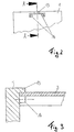
- FIG. 1 An embodiment of a support frame is shown in Fig. 1 as a longitudinal section.
- the form between the two side end elements 1, 2 in the form of End plates 1a, 2a, which are arranged substantially parallel to one another at a distance are, with the transversely arranged above and below longitudinal beams 3 den actual supporting frame, within which a rotatable cable drum 4 via bearing 5 is supported directly on a clamping element 6 designed as a threaded rod 6a.
- the threaded rod 6a is parallel to the longitudinal beams 3 arranged.
- the threaded rod 6a has an external thread at the ends 7 provided; for receiving one end of the threaded rod 6a is used centrally in the end plate 1 formed opening 8, which with a corresponding Internal thread 9 is provided so that one end of the threaded rod 6a Screw connection is firmly connected to the end plate 1a.
- the other end of the Threaded rod 6a protrudes through a likewise central opening 10 in the end plate 2a extending beyond this so that by means of a nut 11 a Screwing the end plates 1a, 2a is made possible via the threaded rod 6a.
- the cable drum 4 rotatably supported on the threaded rod 6a via the bearings 5 is driven by a drive shaft 12 provided with external teeth, which for this purpose is formed in the longitudinal direction in the inner surface of the cable drum 4 Internal toothing engages; the drive shaft 12 penetrates the face plate 1 through a opening provided for this purpose.
- FIG. 2 shows a simple, yet very effective fixation of the longitudinal beams 3 on the end plate 1a, 2a;
- Fig. 3 shows a partial section along the section line A-A 2.
- the end plate 1 a, 2 a is at the associated points Provide protrusions.
- this is at the edge the end plate 1a, 2a arranged projection as a stop bar 13 with cuboid cross-section, the stop surface parallel to Longitudinal direction of the support frame runs.
- the longitudinal beams 3 have a U-profile which is dimensioned so that the End of the longitudinal beam 3 - as shown in the figures - in each case in the form gap formed by the cams 14 and the stop bar 13 can be used.
- the Distance of the cams 14 is chosen so that the outer surfaces of the inner Side surfaces and the inner bottom surface of the longitudinal beam 3 used Touch condition, which prevents a lateral displacement of the side member 3 becomes.
- the stop bar 13 can also be designed as a cam his. It is only important that the side member 3 is essentially free of play between the Projections 13, 14 can be used in a form-fitting manner.
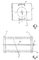
- FIG. 4 is another variant in partial section across the support frame according to Fig. 1 shown with which a play-free fixation of the side members 3 is guaranteed becomes.
- the end plates 1a, 2a at the appropriate points Wells in the form of slot-like recesses 15 with a U-shaped Cross-section is formed and the recess is in shape to the shape of the Complementary.
- This design variant is also important the side member fixation that by inserting the side member 3 in a essential play-free positive connection between the end plates 1a, 2a and the side members 3 can be produced.
Description
- Fig. 1
- einen Längsschnitt durch einen Tragrahmen mit einer gleichzeitig als Drehachse der Seiltrommel dienenden Gewindestange als Spannelement,
- Fig. 2
- einen Teilschnitt quer durch den Tragrahmen gemäß Fig. 1 mit einem an der Stirnwand fixierten Längsträger mit U-Profil,
- Fig. 3
- einen Teilschnitt entlang der Schnittlinie A-A gemäß Fig. 2,
- Fig. 4
- einen Teilschnitt quer durch den Tragrahmen gemäß Fig. 1 mit einem an der Stirnwand mittels Vertiefungen fixierten Längsträger mit U-Profil und
- Fig. 5
- eine Draufsicht des Tragrahmens gemäß Fig. 4.
Claims (13)
- Tragrahmen für zugmittelbetriebene Hebezeuge mit einer Seiltrommel (4), mit mindestens zwei zwischen zwei seitlichen Stimelementen (1,2) angeordneten Längsträgem (3), deren Enden jeweils im Bereich der Stimelemente (1,2) über die Längsträgerrichtung in ihrer Lage fixiert sind,
dadurch gekennzeichnet, daß zwischen den Stimelementen (1, 2) zur Abstützung der Seiltrommel (4) und als Spannelement (6) für die Stimelemente (1,2) eine Gewindestange (6a) angeordnet ist. - Tragrahmen nach Anspruch 1,
dadurch gekennzeichnet, daß das Spannelement (6) eine Gewindestange (6a) mit jeweils mindestens an den Enden ausgebildetem Außengewinde ist. - Tragrahmen nach Anspruch 1 oder 2,
dadurch gekennzeichnet, daß die Stimelemente (1,2) plattenförmig ausgebildet sind. - Tragrahmen nach einem der Ansprüche 2 oder 3,
dadurch gekennzeichnet, daß ein Stimelement (1) eine Aufnahmeöffnung mit Innengewinde (9) zur Aufnahme der Gewindestange (6a) und das andere Stimelement (2) eine Durchtrittsöffnung für die Gewindestange (6a) aufweist. - Tragrahmen nach einem der Ansprüche 2 bis 4,
dadurch gekennzeichnet, daß die Stirnelemente (1,2) durch Verschraubung über die Gewindestange (6a) gegeneinander verspannbar sind. - Tragrahmen nach einem der Ansprüche 1 bis 5,
dadurch gekennzeichnet, daß die Längsträger (3) einen Querschnitt mit U-Profil aufweisen. - Tragrahmen nach einem der Ansprüche 1 bis 6,
dadurch gekennzeichnet, daß die Stimelemente (1,2) zur Fixierung der Längsträgerenden Vertiefungen aufweisen, die zur Form der Längsträgerenden komplementär sind. - Tragrahmen nach einem der Ansprüche 1 bis 6,
dadurch gekennzeichnet, daß die Stirnelemente (1,2) zur Fixierung der Längsträgerenden Vorsprünge aufweisen. - Tragrahmen nach Anspruch 8,
dadurch gekennzeichnet, daß die Vorsprünge von Vorrichtungsteilen der Stimelemente (1,2) gebildete Anschlagflächen (13) sind. - Tragrahmen nach Anspruch 8,
dadurch gekennzeichnet, daß die Vorsprünge von Vorrichtungsteilen der Stimelemente (1,2) gebildete Nocken (14) sind. - Tragrahmen nach einem der Ansprüche 1 bis 10,
dadurch gekennzeichnet, daß die Seiltrommel (4) über Lager (5) direkt auf der Gewindestange (6) abgestützt ist. - Tragrahmen nach einem der Ansprüche 1 bis 2,
dadurch gekennzeichnet, daß mindestens eines der Stimelemente (2) einen Durchbruch für eine Antriebswelle (12) aufweist. - Tragrahmen nach Anspruch 4,
dadurch gekennzeichnet, daß die Antriebswelle (12) eine Außenverzahnung und die Innenseite der Seiltrommel mindestens in dem entsprechenden Bereich eine Innenverzahnung aufweist.
Applications Claiming Priority (2)
| Application Number | Priority Date | Filing Date | Title |
|---|---|---|---|
| DE19602927 | 1996-01-18 | ||
| DE19602927A DE19602927A1 (de) | 1996-01-18 | 1996-01-18 | Tragrahmen, insbesondere für zugmittelbetriebene Hebezeuge |
Publications (2)
| Publication Number | Publication Date |
|---|---|
| EP0785165A1 EP0785165A1 (de) | 1997-07-23 |
| EP0785165B1 true EP0785165B1 (de) | 2002-05-02 |
Family
ID=7783849
Family Applications (1)
| Application Number | Title | Priority Date | Filing Date |
|---|---|---|---|
| EP97250005A Expired - Lifetime EP0785165B1 (de) | 1996-01-18 | 1997-01-15 | Tragrahmen, insbesondere für zugmittelbetriebene Hebezeuge |
Country Status (4)
| Country | Link |
|---|---|
| US (1) | US5816564A (de) |
| EP (1) | EP0785165B1 (de) |
| JP (1) | JPH09301686A (de) |
| DE (2) | DE19602927A1 (de) |
Families Citing this family (14)
| Publication number | Priority date | Publication date | Assignee | Title |
|---|---|---|---|---|
| FI107798B (fi) * | 1998-11-05 | 2001-10-15 | Kci Kone Cranes Int Oy | Telan voimansiirto- ja laakerointijärjestely |
| US6276666B1 (en) | 2000-04-05 | 2001-08-21 | Lockheed Martin Corporation | Apparatus and method for moving a load |
| US7118095B1 (en) * | 2003-07-07 | 2006-10-10 | Stidham Oren W | Lifting reel mounted on a tree stand |
| US7300036B2 (en) * | 2004-03-05 | 2007-11-27 | Dinius Michael J | Pulley and hoist adapter for bolts all-thread rods |
| US6996911B1 (en) | 2004-03-05 | 2006-02-14 | Dinius Michael J | Combination level and squaring tool |
| DE102005029113B3 (de) * | 2005-06-23 | 2006-08-10 | Demag Cranes & Components Gmbh | Tragrahmen eines Hebezeuges |
| DE102007014505A1 (de) * | 2007-03-27 | 2008-10-02 | Demag Cranes & Components Gmbh | Hebezeug |
| CA2781546C (en) | 2009-11-21 | 2016-10-04 | Demag Cranes & Components Gmbh | Lifting apparatus, especially cable traction mechanism, comprising connecting possibilities |
| DE102009054226B3 (de) | 2009-11-21 | 2011-02-24 | Demag Cranes & Components Gmbh | Grundrahmen eines Hebezeug, insbesondere Seilzuges, mit Anschlussmöglichkeiten |
| DE102009054225A1 (de) | 2009-11-21 | 2011-06-09 | Demag Cranes & Components Gmbh | Grundrahmen eines Hebezeug, inbesondere Seilzuges, und ein Verfahren zu dessen Montage, Demontage oder Umbau |
| DE102010026651B4 (de) * | 2010-07-09 | 2017-02-16 | Abus Kransysteme Gmbh | Traggehäuse für ein Seilzuggehäuse |
| NO334235B1 (no) * | 2010-09-01 | 2014-01-20 | Aker Pusnes As | Girdrivanordning |
| DE102015108265A1 (de) | 2015-05-26 | 2016-12-01 | Terex MHPS IP Management GmbH | Grundrahmen eines Hebezeuges, insbesondere eines Seilzuges |
| US20200115198A1 (en) | 2018-10-11 | 2020-04-16 | Jeffrey S. Armfield | Modular powered hoist with multifunctional baseplate |
Family Cites Families (14)
| Publication number | Priority date | Publication date | Assignee | Title |
|---|---|---|---|---|
| DE746602C (de) * | ||||
| DE561113C (de) * | 1932-10-10 | Wilhelm Puetzer | Unverschiebliche Lagerung eines Getriebegehaeuses an dem Seitenschild eines Elektroflaschenzuges | |
| GB144461A (en) * | 1919-05-30 | 1920-06-17 | George Wood | Improvements in or relating to rollers or pulleys for colliery haulage and like purposes |
| GB172405A (en) * | 1920-09-04 | 1921-12-05 | Andrew Hanson Cook | Improvements in rollers for carrying haulage ropes and other purposes |
| US2512564A (en) * | 1945-06-14 | 1950-06-20 | Wilburne A Dickson | Cathead |
| DE842705C (de) * | 1951-03-30 | 1952-06-30 | Walter Sichelschmidt | Elektrowinde, Elektroflaschenzug od. dgl. mit Schutzmantel |
| DE3405759C2 (de) * | 1984-02-17 | 1986-10-16 | Willy Habegger AG, Thun | Seilflasche |
| US4736929A (en) * | 1986-06-30 | 1988-04-12 | Warn Industries, Inc. | Winch having split housing and drive components |
| FI76541C (fi) * | 1986-12-23 | 1988-11-10 | Kone Oy | Lyftmaskineri. |
| SE468713B (sv) * | 1991-05-27 | 1993-03-08 | Ulvator Innovation Ab | Verktyg foer uppbaerande av en kropp med en spole av t ex kabel eller lina |
| US5186410A (en) * | 1991-06-12 | 1993-02-16 | Toews Timothy R | Wire reel mechanism |
| DE4310770A1 (de) * | 1993-04-02 | 1994-10-06 | Krupp Industrietech | Motorseilwinde |
| US5573091A (en) * | 1994-12-09 | 1996-11-12 | Hung; Michael | Electrically powered or manually driven clutch and brake assembly for electric winch |
| US5611522A (en) * | 1996-04-01 | 1997-03-18 | Knight Industries, Inc. | Hydraulically actuated portable hoist |
-
1996
- 1996-01-18 DE DE19602927A patent/DE19602927A1/de not_active Withdrawn
-
1997
- 1997-01-15 EP EP97250005A patent/EP0785165B1/de not_active Expired - Lifetime
- 1997-01-15 DE DE59707122T patent/DE59707122D1/de not_active Expired - Fee Related
- 1997-01-16 JP JP9017883A patent/JPH09301686A/ja active Pending
- 1997-01-21 US US08/786,431 patent/US5816564A/en not_active Expired - Fee Related
Also Published As
| Publication number | Publication date |
|---|---|
| EP0785165A1 (de) | 1997-07-23 |
| DE59707122D1 (de) | 2002-06-06 |
| DE19602927A1 (de) | 1997-07-24 |
| US5816564A (en) | 1998-10-06 |
| JPH09301686A (ja) | 1997-11-25 |
Similar Documents
| Publication | Publication Date | Title |
|---|---|---|
| DE3007245C2 (de) | Zahnbesatz für Walzen und Tragsegmente von Textilmaschinen | |
| EP0785165B1 (de) | Tragrahmen, insbesondere für zugmittelbetriebene Hebezeuge | |
| AT405757B (de) | Verbindungsstück für die lösbare verbindung zweier profilstäbe, vorzugsweise aus leichtmetall | |
| DE3701530A1 (de) | Gezahnte ankerschiene | |
| DE2422959B2 (de) | Kettenflaschenzug | |
| WO2020151889A1 (de) | Pedelec-tretlagerantriebseinheit | |
| EP0641416B1 (de) | Schlauchpumpe | |
| DE2119479C3 (de) | Tragrahmen für Frachtcontainer unterschiedlicher Länge | |
| DE19715496C1 (de) | Justierelement | |
| EP0922007B1 (de) | Seilzug mit elastischem rahmen | |
| EP0367755B1 (de) | Mitnehmeranordnung | |
| DE10358886B4 (de) | Betonrundschalung | |
| DE10343539B4 (de) | Förderband mit einer Antriebseinheit | |
| DE3017196A1 (de) | Gegenueber aggressiven stoffen resistentes kunststoffgehaeuse | |
| DE102004009062B4 (de) | Fahrwerk | |
| DE202005020270U1 (de) | Torsionsachse und Parkvorrichtung mit derselben | |
| EP0250638A1 (de) | Druckfedernspanner | |
| EP3606767B1 (de) | Achssystem | |
| DE19703495C2 (de) | Trogmischer | |
| EP0168517B1 (de) | Spannvorrichtung für Achsfedern zum Ein- und Ausbauen von Stossdämpfern bei Kraftwagen | |
| DE3032227C2 (de) | Beschlag für Mehrfunktions-Wohnraumdachfenster | |
| EP2235325B1 (de) | Firstmeisselträgerverstellung und sicherungselement hierfür | |
| DE2851739C2 (de) | Schwungradbefestigung einer Spindelschlagpresse | |
| DE3448546C2 (de) | Kreiselegge | |
| DE3525953C1 (de) | Axial selbstsichernder Bolzen für einseitig zugängliche Bolzenverbindungen |
Legal Events
| Date | Code | Title | Description |
|---|---|---|---|
| PUAI | Public reference made under article 153(3) epc to a published international application that has entered the european phase |
Free format text: ORIGINAL CODE: 0009012 |
|
| AK | Designated contracting states |
Kind code of ref document: A1 Designated state(s): DE FR GB IT |
|
| 17P | Request for examination filed |
Effective date: 19980112 |
|
| 17Q | First examination report despatched |
Effective date: 20000215 |
|
| GRAG | Despatch of communication of intention to grant |
Free format text: ORIGINAL CODE: EPIDOS AGRA |
|
| GRAG | Despatch of communication of intention to grant |
Free format text: ORIGINAL CODE: EPIDOS AGRA |
|
| GRAH | Despatch of communication of intention to grant a patent |
Free format text: ORIGINAL CODE: EPIDOS IGRA |
|
| REG | Reference to a national code |
Ref country code: GB Ref legal event code: IF02 |
|
| RAP1 | Party data changed (applicant data changed or rights of an application transferred) |
Owner name: DEMAG CRANES & COMPONENTS GMBH |
|
| GRAH | Despatch of communication of intention to grant a patent |
Free format text: ORIGINAL CODE: EPIDOS IGRA |
|
| GRAA | (expected) grant |
Free format text: ORIGINAL CODE: 0009210 |
|
| AK | Designated contracting states |
Kind code of ref document: B1 Designated state(s): DE FR GB IT |
|
| REG | Reference to a national code |
Ref country code: GB Ref legal event code: FG4D Free format text: NOT ENGLISH |
|
| GBT | Gb: translation of ep patent filed (gb section 77(6)(a)/1977) |
Effective date: 20020502 |
|
| REF | Corresponds to: |
Ref document number: 59707122 Country of ref document: DE Date of ref document: 20020606 |
|
| ET | Fr: translation filed | ||
| PG25 | Lapsed in a contracting state [announced via postgrant information from national office to epo] |
Ref country code: GB Free format text: LAPSE BECAUSE OF NON-PAYMENT OF DUE FEES Effective date: 20030115 |
|
| PLBE | No opposition filed within time limit |
Free format text: ORIGINAL CODE: 0009261 |
|
| STAA | Information on the status of an ep patent application or granted ep patent |
Free format text: STATUS: NO OPPOSITION FILED WITHIN TIME LIMIT |
|
| 26N | No opposition filed |
Effective date: 20030204 |
|
| GBPC | Gb: european patent ceased through non-payment of renewal fee | ||
| PG25 | Lapsed in a contracting state [announced via postgrant information from national office to epo] |
Ref country code: FR Free format text: LAPSE BECAUSE OF NON-PAYMENT OF DUE FEES Effective date: 20030930 |
|
| REG | Reference to a national code |
Ref country code: FR Ref legal event code: ST |
|
| PGFP | Annual fee paid to national office [announced via postgrant information from national office to epo] |
Ref country code: DE Payment date: 20050106 Year of fee payment: 9 |
|
| PG25 | Lapsed in a contracting state [announced via postgrant information from national office to epo] |
Ref country code: IT Free format text: LAPSE BECAUSE OF NON-PAYMENT OF DUE FEES;WARNING: LAPSES OF ITALIAN PATENTS WITH EFFECTIVE DATE BEFORE 2007 MAY HAVE OCCURRED AT ANY TIME BEFORE 2007. THE CORRECT EFFECTIVE DATE MAY BE DIFFERENT FROM THE ONE RECORDED. Effective date: 20050115 |
|
| PG25 | Lapsed in a contracting state [announced via postgrant information from national office to epo] |
Ref country code: DE Free format text: LAPSE BECAUSE OF NON-PAYMENT OF DUE FEES Effective date: 20060801 |