EP0784827B1 - Procede et appareil de determination de l'orientation angulaire precise de symboles de code a barres dans des images ccd bidimensionnelles - Google Patents
Procede et appareil de determination de l'orientation angulaire precise de symboles de code a barres dans des images ccd bidimensionnelles Download PDFInfo
- Publication number
- EP0784827B1 EP0784827B1 EP94927978A EP94927978A EP0784827B1 EP 0784827 B1 EP0784827 B1 EP 0784827B1 EP 94927978 A EP94927978 A EP 94927978A EP 94927978 A EP94927978 A EP 94927978A EP 0784827 B1 EP0784827 B1 EP 0784827B1
- Authority
- EP
- European Patent Office
- Prior art keywords
- directional range
- directional
- selecting
- accordance
- determining
- Prior art date
- Legal status (The legal status is an assumption and is not a legal conclusion. Google has not performed a legal analysis and makes no representation as to the accuracy of the status listed.)
- Expired - Lifetime
Links
Images


Classifications
-
- G—PHYSICS
- G06—COMPUTING; CALCULATING OR COUNTING
- G06K—GRAPHICAL DATA READING; PRESENTATION OF DATA; RECORD CARRIERS; HANDLING RECORD CARRIERS
- G06K7/00—Methods or arrangements for sensing record carriers, e.g. for reading patterns
- G06K7/10—Methods or arrangements for sensing record carriers, e.g. for reading patterns by electromagnetic radiation, e.g. optical sensing; by corpuscular radiation
- G06K7/14—Methods or arrangements for sensing record carriers, e.g. for reading patterns by electromagnetic radiation, e.g. optical sensing; by corpuscular radiation using light without selection of wavelength, e.g. sensing reflected white light
- G06K7/1404—Methods for optical code recognition
- G06K7/1439—Methods for optical code recognition including a method step for retrieval of the optical code
- G06K7/1452—Methods for optical code recognition including a method step for retrieval of the optical code detecting bar code edges
-
- G—PHYSICS
- G06—COMPUTING; CALCULATING OR COUNTING
- G06K—GRAPHICAL DATA READING; PRESENTATION OF DATA; RECORD CARRIERS; HANDLING RECORD CARRIERS
- G06K7/00—Methods or arrangements for sensing record carriers, e.g. for reading patterns
- G06K7/10—Methods or arrangements for sensing record carriers, e.g. for reading patterns by electromagnetic radiation, e.g. optical sensing; by corpuscular radiation
- G06K7/14—Methods or arrangements for sensing record carriers, e.g. for reading patterns by electromagnetic radiation, e.g. optical sensing; by corpuscular radiation using light without selection of wavelength, e.g. sensing reflected white light
- G06K7/1404—Methods for optical code recognition
- G06K7/1439—Methods for optical code recognition including a method step for retrieval of the optical code
- G06K7/1443—Methods for optical code recognition including a method step for retrieval of the optical code locating of the code in an image
-
- G—PHYSICS
- G06—COMPUTING; CALCULATING OR COUNTING
- G06K—GRAPHICAL DATA READING; PRESENTATION OF DATA; RECORD CARRIERS; HANDLING RECORD CARRIERS
- G06K7/00—Methods or arrangements for sensing record carriers, e.g. for reading patterns
- G06K7/10—Methods or arrangements for sensing record carriers, e.g. for reading patterns by electromagnetic radiation, e.g. optical sensing; by corpuscular radiation
- G06K7/14—Methods or arrangements for sensing record carriers, e.g. for reading patterns by electromagnetic radiation, e.g. optical sensing; by corpuscular radiation using light without selection of wavelength, e.g. sensing reflected white light
- G06K7/1404—Methods for optical code recognition
- G06K7/1439—Methods for optical code recognition including a method step for retrieval of the optical code
- G06K7/1456—Methods for optical code recognition including a method step for retrieval of the optical code determining the orientation of the optical code with respect to the reader and correcting therefore
-
- G—PHYSICS
- G06—COMPUTING; CALCULATING OR COUNTING
- G06V—IMAGE OR VIDEO RECOGNITION OR UNDERSTANDING
- G06V10/00—Arrangements for image or video recognition or understanding
- G06V10/20—Image preprocessing
- G06V10/24—Aligning, centring, orientation detection or correction of the image
-
- G—PHYSICS
- G06—COMPUTING; CALCULATING OR COUNTING
- G06V—IMAGE OR VIDEO RECOGNITION OR UNDERSTANDING
- G06V10/00—Arrangements for image or video recognition or understanding
- G06V10/20—Image preprocessing
- G06V10/25—Determination of region of interest [ROI] or a volume of interest [VOI]
-
- G—PHYSICS
- G06—COMPUTING; CALCULATING OR COUNTING
- G06V—IMAGE OR VIDEO RECOGNITION OR UNDERSTANDING
- G06V30/00—Character recognition; Recognising digital ink; Document-oriented image-based pattern recognition
- G06V30/10—Character recognition
- G06V30/14—Image acquisition
- G06V30/146—Aligning or centring of the image pick-up or image-field
- G06V30/1475—Inclination or skew detection or correction of characters or of image to be recognised
- G06V30/1478—Inclination or skew detection or correction of characters or of image to be recognised of characters or characters lines
Definitions
- This invention relates to the reading and processing of package labels generally and particularly to systems for locating and extracting and decoding bar codes and other symbols from low resolution, noisy or cluttered CCD images.
- Package handling and sorting operations often require recognition systems for reading bar codes and other symbols which nave been affixed to packages.
- Some types of sorting equipment for example, use bar code recognition systems to sort packages in accordance with information which has been included in the bar code symbol.
- Overhead CCD scanner systems have employed stationary reading devices to scan labels affixed to moving packages.
- Such devices typically include a linear array of photosensitive cells aligned orthogonally to the motion of the package and a lens system for projecting the image at a scanning window onto the linear array.
- the cells of the array are scanned at a rate which is relatively high compared to the motion of the package through the read station.
- the images produced by such scanning equipment are often noisy and of low resolution.
- a further complication to reading a bar code symbol is introduced when the symbol is embedded against a cluttered background on the moving package.
- the cluttered background can result from other information, besides the bar code symbol being scanned, which has been placed on the package in close proximity to the bar code symbol.
- a cluttered or noisy image can also result from stray marks on the package near the bar code symbol, or from a torn, smudged, or mutilated bar code symbol.
- a still further complication to extracting and reading bar code symbols embedded in CCD images relates to limitations in image processing hardware that may be employed to process such images.
- image processing boards typically include only a limited number of convolvers, thereby limiting the number of images that can be simultaneously convolved with a given mask to the number of convolvers on the image processing board. If an image processing application requires the convolution of multiple images in parallel and a separate convolver is not available on the image processing board for each image being convolved, multiple image processing boards will have to be employed thereby substantially increasing the hardware costs associated with implementing an image processing system.
- European patent application EP 0 569 982 A2 discloses a method and an apparatus for processing images with symbols with dense edges.
- the system is adapted to locate at least one object within an intensity image and includes means for analyzing the image with at least two different edge detectors to detect a multiplicity of edges oriented in at least two directional ranges. The edges are compared with predetermined directional ranges.
- the system further comprises means for selecting at least one foreground region in the intensity image. The detected edges in the selected foreground region are angularly oriented substantially in accordance with a target orientation.
- a high speed pattern recognition device is described in the German patent application DE-OS 33 40 705.
- the system bases on the storing of a comparison image and an image to be recognized in separated, addressable memories. Both images are adapted to each other by a stepwise rotation of the comparison image and a counting method processing the adaptation steps.
- a system for determining the fine angular orientation of a bar code symbol in a two-dimensional pixel image is disclosed.
- a window is selected from the two-dimensional image for processing.
- Edge magnitude information and edge direction information are determined for a plurality of pixels in the selected window.
- the edge magnitude and the edge direction of each pixel is associated with at least one of a plurality of directional ranges if the edge magnitude associated with the pixel exceeds a threshold.
- a density value associated with each directional range is determined in accordance with the number of pixels associated with the directional range.
- At least one candidate directional range is selected in accordance with the associated density values.
- the fine angular orientation of a bar code symbol is determined in accordance with the edge directions associated with the candidate directional range.
- a system for determining the fine angular orientation of a bar code symbol in a two-dimensional pixel image is disclosed.
- a window is selected from the two-dimensional image for processing.
- Edge magnitude information and edge direction information are determined for a plurality of pixels in the selected window.
- the edge magnitude and the edge direction of each pixel is associated with at least one of a plurality of directional ranges if the edge magnitude associated with the pixel exceeds a threshold.
- an angular mean value associated with each directional range is determined in accordance with the edge directions associated with the directional range.
- At least one candidate directional range is selected in accordance with the associated angular means values.
- the fine angular orientation of a bar code symbol is determined in accordance with the edge directions associated with the candidate directional range.
- a system for determining the fine angular orientation of a bar code symbol in a two-dimensional pixel image is disclosed.
- a window is selected from the two-dimensional image for processing.
- Edge magnitude information and edge direction information are determined for a plurality of pixels in the selected window.
- the edge magnitude and the edge direction of each pixel is associated with at least one of a plurality of directional ranges if the edge magnitude associated with the pixel exceeds a threshold.
- a noise value associated with each directional range is determined in accordance with the edge directions associated with the directional range.
- At least one candidate directional range is selected in accordance with the associated noise values.
- the fine angular orientation of a bar code symbol is determined in accordance with the edge directions associated with the candidate directional range.
- Figure 1 is a flow diagram illustrating the operation of a preferred embodiment of a system for locating an object in an intensity image according to the present invention.
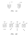
- Figure 2A shows two edge detectors used in connection with a preferred embodiment of the present invention.
- Figure 2B shows four edge detectors used in connection with a further preferred embodiment of the present invention.
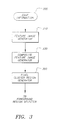
- Figure 3 is a flow diagram illustrating the operation of an edge information comparator according to a preferred embodiment of the present invention.
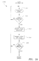
- Figure 3A is a flow diagram illustrating a process for forming binary images according to a preferred embodiment of the present invention.
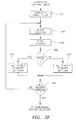
- Figure 3B is a flow diagram illustrating a process for generating feature images from binary images according to a preferred embodiment of the present invention.
- Figure 3C is a flow diagram illustrating the operation of a composite feature image generator according to a preferred embodiment of the present invention.
- Figure 3D is a flow diagram illustrating the operation of an alternative composite feature image generator according to a preferred embodiment of the present invention.
- Figure 3E is a flow diagram illustrating the operation of a still further alternative composite feature image generator according to a preferred embodiment of the present invention.
- Figure 3F is a flow diagram illustrating the operation of a pixel cluster region generator for processing a composite feature image according to a preferred embodiment of the present invention.
- Figure 3G is a diagram showing the operation of an apparatus for efficiently forming a plurality of binary images from an input intensity image according to a preferred embodiment of the present invention.
- Figure 3H is a diagram showing the operation of an apparatus for efficiently forming a composite feature image from pixels representative of a plurality of binary images according to a preferred embodiment of the present invention.
- Figure 4 is a flow diagram illustrating the operation of a foreground region selector according to a preferred embodiment of the present invention.
- Figure 4A shows two connectivity operators employed in connection with alternative preferred embodiments of the present invention.
- Figure 5 is a flow diagram illustrating the operation of a system for extracting information associated with a selected object region from an intensity image according to a preferred embodiment of the present invention.
- Figure 6A shows a exemplary low resolution intensity image representative of an imaged region being scanned.
- Figures 6B-6E show four exemplary binary images which resulted from the application of the edge detectors of Figure 2B to the intensity image of Figure 6A.
- Figures 6F-61 show four exemplary feature images which resulted from the application of the majority dilation and minority erosion process of Figure 3B to the binary images of Figures 6B-6E.
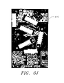
- Figure 6J shows an exemplary composite feature image which resulted from the application of the process of Figure 3C to the feature images of Figures 6F-61.
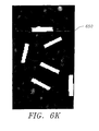
- Figure 6K shows an exemplary composite feature image which resulted from the application of the majority dilation and minority erosion process of Figure 3F to the composite feature image of Figure 6D.
- Figure 7 shows an exemplary packaging label having a plurality of symbols with edges oriented in accordance with different target orientations.
- Figure 8 is a flow diagram illustrating the operation of a pre-processing step employed in connection with a preferred embodiment of the present invention.
- Figure 8A shows the contour of an exemplary package positioned on a dark belt.
- Figures 9A, 9B show a flow diagram illustrating the operation of a preferred system for determining the fine angular orientation of an object in an intensity image according to the present invention.
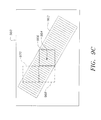
- Figure 9C shows a portion of an exemplary intensity image which includes a selected object region that has a plurality of selected pixel windows superimposed thereon.
- Figure 9D shows a preferred group of directional ranges used for determining the fine angular orientation of a bar code symbol in an intensity image according to the present invention.
- Figure 10 is flow diagram illustrating the operation of an alternative preferred embodiment for determining the coarse orientation of an object in an intensity image according to the present invention.
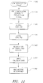
- Figure 11 is a flow diagram illustrating the operation of a preferred system for determining bar widths from a two-dimensional image representative of a bar code symbol according to the present invention.
- Figure 12 shows an exemplary low resolution image for processing by the image processing system of the present invention.
- Figure 13A shows a one-dimensional intensity projection image derived from a low resolution image representative of a bar code symbol according to the present invention.
- Figure 13B shows an exemplary projection signal derived from the application of the first global scaling method of the present invention to the projection signal of Figure 13A.
- Figure 13C shows an exemplary projection signal derived from the application of the local scaling and interpolation methods of the present invention to the projection signal of Figure 13B.
- Figure 13D shows an exemplary projection signal derived from the application of the second global scaling method of the present invention to the projection signal of Figure 13C.
- Figure 13E is an expanded representation of the projection signal of Figure 13D.
- Figure 14 shows an exemplary low resolution image having a plurality of scan lines superimposed thereon in accordance with a preferred embodiment of the present invention.
- the present invention is directed to a system for locating an object within an intensity image, a system for determining the fine angular orientation and/or position of an object within an intensity image and a system for image processing.
- the object locating system is discussed in connection with Figures 1-8; the object orientation system is discussed in connection with Figures 9 and 10; and the image processing system is discussed in connection with Figures 11-14.
- the term "object” refers to symbols, figures, patterns, shapes or areas having dense edges. Without limitation, the term “object” includes bar code symbols, stacked bar code symbols, and arrays of squares, hexagons and other polygons.
- intensity image 100 is preferably a digitized gray scale representation of an imaged region being scanned.
- intensity image 100 is a low resolution pixel image derived from a linear array of CCDs.
- the system shown includes means 200 for analyzing an intensity image with at least two different edge detectors to detect a multiplicity of edges oriented in at least two directional ranges.
- Means 300 is provided for comparing information representative of detected edges angularly oriented in a first of said at least two directional ranges to information representative of detected edges angularly oriented in a second of said at least two directional ranges. Based on the results of comparisons made by means 300, means 400 selects at least one foreground region from intensity image 100 wherein detected edges are angularly oriented substantially in accordance with a target orientation.
- Means 500 is provided for extracting from intensity image 100 information that is representative of the foreground region selected by means 400. In the preferred embodiment, means 500 determines the position ( i.e ., the spatial coordinates) within intensity image 100 of the centroid (or center of mass) of an object region that corresponds to the foreground region selected by means 400.
- edge detectors 210, 220 which are employed by means 200 in connection with a preferred embodiment of the present invention.
- means 200 applies edge detector 210 to intensity image 100 on a pixel-by-pixel basis to determine the X component ( ⁇ X) of each edge gradient.
- edge detector 220 is applied to intensity image 100 on a pixel-by-pixel basis to determine the Y component ( ⁇ Y) of each edge gradient.
- intensity image 100 is formed of 782 x 1288 8-bit pixels and M n is normalized to range from 0-127. This normalization is achieved by dividing the result of equation (1) by 8.
- edge detectors 230, 240, 250, 260 of Figure 2B are applied by means 200 to determine edge magnitude information and edge direction information at each pixel in intensity image 100. More particularly, edge detector 230 is applied to intensity image 10C on a pixel-by-pixel basis to determine magnitude information corresponding to edges angularly oriented in a directional range within 22.5 degrees on either side of the 0 degree axis; edge detector 240 is applied to intensity image 100 on a pixel-by-pixel basis to determine magnitude information corresponding to edges angularly oriented in a directional range within 22.5 degrees on either side of the 45 degree axis; edge detector 250 is applied to intensity image 100 on a pixel-by-pixel basis to determine magnitude information corresponding to edges angularly oriented in a directional range within 22.5 degrees on either side of the 90 degree axis; and edge detector 260 is applied to intensity image 100 on a pixel-by-pixel basis to determine magnitude information corresponding to edges angularly oriented in a directional range within 22.5 degrees
- Edge information from means 200 is next applied to edge information comparator 300.
- edge information comparator 300 is comprised of means 310 for generating at least two feature images, means 330 for forming a composite feature image and means 350 for forming a pixel cluster region in a composite feature image.
- means 310 generates at least two feature images by associating the edge magnitude information determined for each pixel in intensity image 100 with one of at least two corresponding directional ranges.
- edge detectors 210, 220 are used to determine the angular orientation of each edge detected from intensity image 100, and each detected edge is then classified as being angularly oriented in one of at least three directional ranges. For example, each detected edge may be classified as being oriented in either (i) a first directional range within 30 degrees on either side of the 0 degree axis, (ii) a second directional within 30 degrees on either side of the 60 degree axis or (iii) a third directional within 30 degrees on either side of the 120 degree axis.
- each feature image is formed of binary pixels which are used to represent the detected edges which have been associated with that respective feature image.
- the position of each binary pixel set high (or set white) in a given feature image preferably corresponds to the position in intensity image 100 of the detected edges associated with that feature image.
- each edge detected by detectors 210, 220 is classified as being angularly oriented in one or two of at least three partially overlapping directional ranges.
- the preferred degree of overlap is approximately 5 degrees on either side of each directional range, although other amounts of overlap may be used.
- each detected edge may be classified as being oriented in (i) a first directional range within 35 degrees on either side of the 0 degree axis, (ii) a second directional range within 35 degrees on either side of the 60 degree axis and/or (iii) a third directional range within 35 degrees on either side of the 120 degree axis.
- a detected edge will be classified in only one directional range if it is not oriented in one of the overlapping range portions.
- a detected edge will be classified in two directional ranges if it is oriented in an overlapping range portion.
- means 310 associates the detected edges oriented in that directional range with a corresponding feature image.
- means 310 may classify detected edges into other directional ranges of differing size or direction.
- at least two and more than three directional ranges may be used to classify the detected edges.
- edge detectors 230, 240, 250, 260 may be used by means 310 to classify each edge from an imaged region into one of the four directional ranges associated with those edge detectors.
- Means 310 is preferably formed from means 310a for forming at least two binary images and means 310b for generating at least two feature images from the output of means 310a.
- FIG 3A there is shown a flow diagram illustrating the operation of means 310a for forming at least two binary images, wherein each of the at least two binary images formed corresponds to one of at least two directional ranges of detected edges.
- Means 310a accepts as its input magnitude information and directional information for each edge detected by means 200.
- Means 311 is provided for selecting a detected edge for processing.
- Means 312 compares the magnitude information corresponding to the selected edge to a first predetermined threshold (T 1 ).
- means 313 selects from at least two directional ranges the one directional range corresponding to the direction of the selected edge. If the magnitude information exceeds T 1 , means 313 also selects from at least two binary images the one binary image corresponding to the selected directional range. Means 314 then sets high the pixel in the selected binary image which corresponds in position to the position of the selected edge in intensity image 100. Means 315 is provided for repeating this process from means 311 for each detected edge.
- means 313 selects from at least three directional ranges the one or two directional ranges corresponding to the direction of the selected edge.
- means 313 also selects from at least three binary images the one or two binary images corresponding to the selected directional range(s).
- Means 314 then sets high the pixel(s) in the selected binary image(s) which correspond in position to the position of the selected edge in intensity image 100.
- means 310 accepts as input magnitude information determined by each of edge detectors 230, 240, 250, 260. The magnitude information corresponding to each detected edge is then compared against T 1 . For each edge detected by detector 230 with a magnitude exceeding T 1 , a binary pixel is set high in a first binary image. The position of the binary pixel set high corresponds to the position in intensity image 100 of the edge represented by that binary pixel.
- a corresponding binary pixel in a second binary image is set high; for each edge detected by detector 250 with a magnitude exceeding T 1 , a corresponding binary pixel in a third binary image is set high; and for each edge detected by detector 260 with a magnitude exceeding T 1 , a corresponding binary pixel in a fourth binary image is set high.
- Figure 6A shows an exemplary low resolution intensity image (610) for processing by the object locator system of the present invention.
- Figure 6B-6E show four binary images which resulted from application of edge detectors 230, 240, 250, 260 to the intensity image of Figure 6A.
- the white pixels in first binary image 620 represent edges detected by detector 230 with magnitudes exceeding T 1 and angular orientations in the directional range within 22.5 degrees on either side of the 0 degree axis;
- the white pixels in second binary image 622 represent edges detected by detector 240 with magnitudes exceeding T 1 and angular orientations in the directional range within 22.5 degrees on either side of the 45 degree axis;
- the white pixels in third binary image 624 represent edges detected by detector 250 with magnitudes exceeding T 1 and angular orientations in the directional range within 22.5 degrees on either side of the 90 degree axis;
- the white pixels in fourth binary image 626 represent edges detected by detector 260 with magnitudes exceeding T 1 and angular orientations in the directional range within 22.5 degrees on either side of the 135 degree axis.
- means 310b subjects each of the at least two binary images output by means 310a to a filtering process referred to as weighed morphology or "majority dilation/minority erosion". This process is used to "dilate” areas in each binary image where the concentration of pixels set high exceeds a second predetermined threshold (T 2 ), and to "erode” areas in each binary image where the concentration of binary pixels set high does not exceed T 2 . In a preferred embodiment of means 310b, this majority dilation/minority erosion process is also used to simultaneously perform "subsampling" on each binary image. According to this embodiment, each of the at least two binary images is divided into a plurality of regions or blocks.
- a binary image 782 x 1288 pixels in dimension would preferably be divided into pixel blocks 8 x 8 pixels in size.
- concentration of binary pixels set high in each block of the plurality of blocks is determined and compared against T 2 .
- An output binary image (or feature image) is then formed by representing each block from the binary image with a single binary pixel in the feature image.
- the single binary pixel in the feature image is set high when the corresponding block in the binary image has a determined concentration which exceeds T 2 .
- the single binary pixel in the feature image is set low when the corresponding block in the binary image has a determined concentration which does not exceed T 2 .
- a feature image which is 97 x 161 pixels in dimension will be formed from a binary image which is 782 x 1288 pixels in dimension.
- means 310b for generating at least two feature images from at least two binary images according to the majority dilation/minority erosion process described above.
- means 316 is provided for tiling each of the binary images into a plurality of blocks.
- One block from the plurality of tiled blocks is then selected by means 317 and the number of binary pixels set high in the selected block is determined by pixel counter 318.
- Comparing means 319 is provided for comparing the number of pixels determined by counter 318 to T 2 . If the number of binary pixels set high in the selected block exceeds T 2 , then means 320 sets a corresponding binary pixel in a corresponding feature image high (or white).
- FIG. 6F-61 show four exemplary feature images 630, 632, 634, 636 which respectively resulted from the application of the majority dilation/minority erosion process of Figure 3B to binary images 620, 622, 624, 626 of Figures 6B-6E.
- a "sliding" window is applied to each of the at least two binary images.
- the sliding window is, for example, an 8 x 8 block of pixels. This window is first applied to the 8 x 8 block of pixels in the upper left hand corner of a selected binary image. The number of pixels set high in the window is compared against T 2 . If the number of pixels in the window set high exceeds T 2 , then a corresponding binary pixel in a corresponding feature image is set high; otherwise, the corresponding binary pixel in the corresponding feature image is set low. The window is then moved one pixel to the right and the process is repeated. This process continues until the right side of the sliding window reaches the right side of the selected binary image. At this point, the window is moved downward by one pixel and over to the left most column of pixels. This process is repeated until the sliding window reaches the bottom right hand corner of the selected binary image.
- the majority dilation/minority erosion process is achieved by first dividing each of the at least three binary images into a plurality of regions. Next, the concentration of binary pixels set high in each region of the plurality of regions is determined and compared against T 2 . In each region where the determined concentration exceeds T 2 , a pixel cluster region is formed by setting all binary pixels in that region high (or white). In each region where the determined concentration does not exceed T 2 , a blank region is formed by setting all binary pixels in that region low (or black).
- Figure 3C is a flow diagram illustrating the operation of a preferred composite feature image generator according to the present invention.
- first, second, third and fourth feature images are provided to means 330.
- the first feature image having been determined from a first binary image representing edges orientated in the directional range within 22.5 degrees on either side of the 0 degree axis; the second feature image having been determined from a second binary image representing edges orientated in the directional range within 22.5 degrees on either side of the 45 degree axis; the third feature image having been determined from a third binary image representing edges orientated in the directional range within 22.5 degrees on either side of the 90 degree axis; and the fourth feature image having been determined from a fourth binary image representing edges orientated in the directional range within 22.5 degrees on either side of the 135 degree axis.
- pixel selector means 331a, 331b, 331c, 331d are provided for selecting corresponding binary pixels from the first, second, third and fourth feature images.
- First Oring means 332a is provided for performing an exclusive logical OR operation on a binary pixel in the first feature image and a corresponding binary pixel in the third feature image
- second Oring means 332b is provided for performing an exclusive logical OR operation on a binary pixel in the second feature image and a corresponding binary pixel in the fourth feature image.
- the outputs of first Oring means 332a and second Oring means 332b are provided to third ORing means 333 where they are compared on a pixel-by-pixel basis.
- means 333 performs a logical OR operation on its inputs and sets either high or low a corresponding binary pixel in a composite feature image depending on the result of the OR operation.
- the binary pixel set in the composite feature image corresponds in position to the position within each of the four feature images of the binary pixels selected by means 331a, 331b, 331, 331d.
- Figure 6J shows an exemplary composite feature image 640 which resulted from the application of the process of Figure 3C to feature images 630, 632, 634, 636 of Figures 6F-6l.
- Pixel selector means 335a, 335b are provided for selecting corresponding binary pixels from each of first and second feature images.
- Pixel comparator means 336 is provided for setting high a binary pixel in a composite feature image if only one of the two selected corresponding binary pixels is set high.
- pixel comparator means 336 sets high a binary pixel in a composite feature image if only one or only two of the three selected corresponding binary pixels are set high. The pixel set high in the composite feature image corresponds in position to the position within each of the feature images of the selected corresponding binary pixels. This process is repeated on a pixel-by-pixel basis for each group of corresponding pixels in the feature images.
- N feature images are provided to the composite feature image generator, wherein N is greater than or equal to two.
- Means 340 are provided for selecting a corresponding pixel from each of M feature images, wherein M is greater than or equal to two and less than or equal to N (for bar code symbols, M is preferably two). At least two of the M selected corresponding binary pixels are preferably selected from feature images representing edges oriented in subsequent directional ranges.
- the two selected corresponding binary pixels are preferably from either the first and second, or the second and third, or the third and fourth, or the fourth and first feature images.
- Means are also provided for selecting a pixel from a composite feature image; the selected pixel in the composite feature image corresponds in position to the position within each of the M feature images of the selected corresponding binary pixels.
- the selected pixel from the composite feature image is then set high by pixel comparator 342 if at least one of the M selected corresponding binary pixels is set high and less than all of the M selected corresponding binary pixels are set high. This process is repeated on a pixel-by-pixel basis for each pixel in the composite feature image.
- Pixel cluster region generator 350 filters the composite feature image using a modified version of the majority dilation/minority erosion described above.
- pixel cluster region generator 350 is used to "dilate” areas in the composite feature image where the concentration of pixels set high exceeds a third predetermined threshold (T 3 ), and to "erode" areas in the composite feature image where the concentration of binary pixels set high does not exceed T 3 .
- this majority dilation/minority erosion process is achieved by applying a "sliding" window to the input composite feature image.
- a window (preferably 3 x 3 pixels in dimension) is first applied to the pixels in the upper left hand corner of the input composite feature image.
- a window 3 x 3 pixels in dimension would first be applied to the 3 x 3 block of pixels in the upper left hand corner of the input composite feature image.
- the number of pixels set high in the window is compared against T 3 . If the number of pixels in the window set high exceeds T 3 , then a corresponding pixel positioned in the center of the 3 x 3 window will be set high in the output composite feature image; otherwise, the corresponding pixel in the output composite feature image will be set low.
- the window is then moved one pixel to the right and the process is repeated.
- FIG. 6K shows an exemplary output composite feature image (650) which resulted from the application of the majority dilation/minority erosion process described above to composite feature image 640 of Figure 6J.
- the majority dilation/minority erosion process is achieved by first dividing the composite feature image into a plurality of regions. Next, the concentration of binary pixels set high in each region of the plurality of regions is determined and compared against T 3 , In each region where the determined concentration exceeds T 3 , a pixel cluster region is formed by setting all binary pixels in that region high (or white). In each region where the determined concentration does not exceed T 3 , a blank region is formed by setting all binary pixels in that region low (or black).
- Means 352 is provided for tiling each of the composite feature image into a plurality of blocks.
- One block from the plurality of tiled blocks is then selected by means 354 and the number of binary pixels set high in the selected block is determined by pixel counter means 356.
- Comparing means 358 is provided for comparing the number of pixels determined by means 356 to T 3 . If the number of binary pixels set high in the selected block exceeds T 3 , then means 360 sets all binary pixels in the selected block high. If the number of binary pixels set high in the selected block does not exceed T 3 , then means 362 sets all binary pixels in the selected block low.
- Means 364 is provided for repeating this process from means 354 for each tiled block.
- system 370 for efficiently forming a plurality of binary images from an input intensity image according to a preferred embodiment of the present invention.
- the operation implemented by system 370 corresponds in function to that performed by means 310a of Figure 3A.
- system 370 is configured to form four binary images, wherein each binary image corresponds to one of four directional ranges ( i.e ., directional range 0, directional range 1, directional range 2 and directional range 3) of detected edges.
- the binary image corresponding to directional range 0 preferably represents detected edges oriented within 27.5 degrees on either side of the 0 degree axis; the binary image corresponding to directional range 1 preferably represents detected edges oriented within 27.5 degrees on either side of the 45 degree axis; the binary image corresponding to directional range 2 preferably represents detected edges oriented within 27.5 degrees on either side of the 90 degree axis; and the binary image corresponding to directional range 3 preferably represents detected edges oriented within 27.5 degrees on either side of the 135 degree axis.
- System 370 accepts as its input 8-bit pixel values from intensity image 100. These 8-bit input pixels are sequentially selected and applied (in 3x3 windows) to edge detectors 210, 220, thereby yielding an 8-bit ⁇ X value and an 8-bit ⁇ Y value corresponding to each pixel in intensity image 100. Next, for each input pixel selected from intensity image 100, a corresponding pair of ⁇ X, ⁇ Y values are applied to look-up table (LUT) 372.
- LUT look-up table
- ⁇ Y values For each possible pair of ⁇ X, ⁇ Y values that may applied to LUT 372, four corresponding 1-bit values (DIR0, DIR1, DIR2, DIR3) are stored in LUT 372.
- the values of these 1-bit entries stored in LUT 372 are preferably determined prior to the acceptance of intensity image 100 by the present invention.
- the corresponding values of DIRO, DIR1, DIR2 and DIR3 are determined by first applying the ⁇ X, ⁇ Y values corresponding to the table entry to equations (1) and (2) above, thereby calculating a magnitude value (M n ) and a direction value (D n ) corresponding to the table entry.
- the magnitude value (M n ) is less than or equal to the threshold (T 1 )
- the values in the table entry corresponding to DIR0, DIR1, DIR2 and DIR3 are all set to zero. If the magnitude value (M n ) is greater than the threshold (T 1 ), then the direction value (D n ) is compared against direction ranges 0, 1, 2 and 3 to determine which of these four directional ranges includes direction value (D n ).
- D n falls within directional range 0 and not in any of the other directional ranges, then the value in the table entry corresponding to DIR0 will be set high and the values corresponding to DIR1, DIR2 and DIR3 will all be set low; if D n falls within directional range 1 and not within any of the other directional ranges, then the value in the table entry corresponding to DIR1 will be set high and the values corresponding to DIR0, DIR2 and DIR3 will all be set low; if D n falls within directional range 2 and not within any of the other directional ranges, then the value in the table entry corresponding to DIR2 will be set high and the values corresponding to DIR0, DIR1 and DIR3 will all be set low; and if D n falls within directional range 3 and not within any of the other directional ranges, then the value in the table entry corresponding to DIR3 will be set high and the values corresponding to DIR0, DIR1 and DIR2 will all be set low.
- ⁇ X, ⁇ Y values are applied to LUT 372 which then outputs the four 1-bit values DIR0, DIR1, DIR2 and DIR3.
- Each of these values represents a pixel in a binary image which corresponds in location to the position of the selected input pixel in intensity image 100.
- the corresponding 1-bit values DIR0, DIR1, DIR2, DIR3 are grouped to form 4-bit words which are provided to system 380.
- the 4-bit words output by LUT 372 collectively represent four binary images, wherein each binary image corresponds to one of four directional ranges of edges (i.e. directional range 0, directional range 1, directional range 2 and directional range 3). Since these four directional ranges are overlapping, one or two bits within each 4-bit word output by LUT 372 will be set high. In alternate embodiments that employ binary images corresponding to non-overlapping directional ranges, only one bit within each 4-bit word output by LUT 372 may be set high.
- LUT 372 to form separate binary images directly from the outputs of edge detectors 210, 220 substantially simplifies the computations required to implement means 310a in real time.
- the use of LUT 372 to form binary images directly from the outputs of edge detectors 210, 220 eliminates the need to repeatedly calculate the magnitude (M n ) and direction (D n ) of each edge in intensity image 100 in accordance with equations (1) and (2) above. Since equations (1) and (2) are computationally intensive, the use of a look-up table that eliminates the need to repeatedly solve these equations has the advantage of substantially enhancing the operational speed of the present invention.
- system 370 is configured to form four binary images, wherein each binary image corresponds to one of four directional ranges of detected edges, it will be understood by those skilled in the art that system 370 may be configured to form more or fewer than four binary images corresponding to different directional ranges by varying the number of columns and the content of the entries in LUT 372.
- FIG. 3H there is shown a diagram illustrating a system 380 for efficiently forming a composite feature image from data representative of a plurality of binary images according to a preferred embodiment of the present invention.
- the operation implemented by system 380 corresponds in function to the operations shown by Figures 3B and 3C described above.
- System 380 preferably accepts as its inputs the 4-bit words generated by LUT 372. Each 4-bit word is applied to bit shifter 382 which forms two 8-bit words (INPUT WORD 1 and INPUT WORD 2) from each 4-bit word that is applied thereto. More particularly, shifter 382 places the 1-bit value DIR0 in bit position 0 of INPUT WORD 1; shifter 382 places the 1-bit value DIR1 in bit position 6 of INPUT WORD 1; shifter 382 places the 1-bit value DIR2 in bit position 0 of INPUT WORD 2; and shifter 382 places the 1-bit value DIR3 in bit position 0 of INPUT WORD 2.
- Shifter 382 sets bit positions 1-5 and 7 to zero in both INPUT WORD 1 and INPUT WORD 2. Next, the 8-bit value INPUT WORD 1 output by shifter 382 is applied to convolver 384, and the 8-bit value INPUT WORD 2 output by shifter 382 is applied to convolver 386.
- Convolvers 384, 386 represent standard image processing convolvers such as those found on a DatacubeTM MaxvideoTM image processing system. Convolvers 384, 386 are each configured to accept 8-bit words at their inputs, each of the 8-bit words corresponding to an 8-bit pixel. The 8-bit pixels which are input to each convolver collectively correspond to an image which can be thought of as being comprised of a two-dimensional array of 8x8 pixel blocks.
- Each convolver 384, 386 convolves an 8x8 block of input pixels with binary mask 388 by first superimposing binary mask 388 (which is 8x8 pixels in dimension) on a respective 8x8 block of input pixels and then multiplying on a pixel-by-pixel basis each pixel from the 8x8 block of input pixels with the value from binary mask 388 that has been superimposed thereon.
- binary mask 388 which is 8x8 pixels in dimension
- binary mask 388 is preferably 8x8 binary pixels in dimension, wherein all the binary pixels in the mask are set to "1" except the pixels at the corners of the mask which are set to "0". In alternate embodiments, the number of binary pixels set to "1" in mask 388 can range from 0 to 63.
- OUTPUT WORD 1 and OUTPUT WORD 2 are respectively applied to shifter/comparator 390 and shifter/comparator 392.
- Shifter/comparator 390 forms a 6-bit value DIR0 RESULT from bit positions 0-5 of OUTPUT WORD 1, and a 6-bit value DIR1 RESULT from bit positions 6-11 of OUTPUT WORD 1.
- DIRO RESULT is a value ranging from 0-63 representing the 6 least-significant-bits of OUTPUT WORD 1
- DIR1 RESULT is a value ranging from 0-63 representing the 6 most-significant-bits of OUTPUT WORD 1.
- shifter/comparator 392 forms a 6-bit value DIR2 RESULT from bit positions 0-5 of OUTPUT WORD 2, and a 6-bit value DIR3 RESULT from bit positions 6-11 of OUTPUT WORD 2.
- DIR2 RESULT is a value ranging from 0-63 representing the 6 least-significant-bits of OUTPUT WORD 2
- DIR3 RESULT is a value ranging from 0-63 representing the 6 most-significant-bits of OUTPUT WORD 2.
- each DIR0 RESULT value determined by shifter/comparator 390 is substantially equivalent to the output that binary pixel counter 318 would have yielded had counter 318 been applied to a selected 8x8 binary pixel block in the binary image corresponding to directional range 0 (as described above in conjunction with Figure 3G); each DIR1 RESULT value determined by shifter/comparator 390 is substantially equivalent to the output that binary pixel counter 318 would have yielded had counter 318 been applied to a selected 8x8 binary pixel block in the binary image corresponding to directional range 1; each DIR2 RESULT value determined by shifter/comparator 392 is substantially equivalent to the output that binary pixel counter 318 would have yielded had counter 318 been applied to a selected 8x8 binary pixel block in the binary image corresponding to directional range 2; and each DIR3 RESULT value determined by shifter/comparator 392 is substantially equivalent to the output that binary pixel counter 3
- Shifter/comparator 390 next compares each DIR0 RESULT with the predetermined threshold T 2 . If the value of DIRO RESULT is greater than T 2 , then a value F_DIR0 which is output by shifter/comparator 390 is set high; otherwise the value of F_DIR0 is set low. Shifter/comparator 390 also compares each DIR1 RESULT with T 2 and, if DIR1 RESULT is greater than T 2 , then a value F_DIR1 output by shifter/comparator 390 is set high; otherwise the value of F_DIR1 is set low. Similarly, shifter/comparator 392 compares each DIR2 RESULT with T 2 .
- DIR2 RESULT If the value of DIR2 RESULT is greater than T 2 , then a value F_DIR2 output by shifter/comparator 392 is set high; otherwise the value of F_DIR2 is set low. Shifter/comparator 392 also compares each DIR3 RESULT with T 2 and, if DIR3 RESULT is greater than T 2 , then a value F_DIR3 output by shifter/comparator 390 is set high; otherwise the value of F_DIR3 is set low.
- each F_DIR0 value output by shifter/comparator 390 represents a pixel in a feature image corresponding to directional range 0; each F_DIR1 value output by shifter/comparator 390 represents a pixel in a feature image corresponding to directional range 1; each F_DIR2 value output by shifter/comparator 392 represents a pixel in a feature image corresponding to directional range 2; and each F_DIR3 value output by shifter/comparator 392 represents a pixel in a feature image corresponding to directional range 3.
- the four 1-bit values F_DIR0, F_DIR1, F_DIR2, F_DIR3 are next applied to LUT 394.
- the operation implemented by LUT 394 preferably corresponds in function to one of the voting operations shown in Figures 3C-3E described above.
- a single corresponding 1-bit value (Output) is stored in LUT 394.
- the values of the 1-bit Output entries stored in LUT 394 are preferably determined prior to the acceptance of intensity image 100 by the present invention.
- a corresponding 1-bit Output value is determined by performing a first exclusive logical OR operation on F_DIR0 and F_DIR2, and a second exclusive logical OR operation on F_DIR1 and F_DIR3. A logical OR operation is then performed on the results of the first and second exclusive OR operations, thereby yielding the 1-bit Output value corresponding to the table entry.
- each 1-bit Output value that is output by LUT 394 corresponds to a pixel in a composite feature image.
- LUT 394 is configured to form a composite feature image from four feature images, wherein each feature image corresponds to one of four directional ranges of detected edges, it will be understood by those skilled in the art that LUT 394 may be configured to form a composite feature image from more or fewer than four feature images corresponding to different directional ranges by varying the number of columns and the content of the entries in LUT 394. In this way, LUT 394 can be used to implement any logical voting operation.
- the output of edge information comparator 300 (i.e ., a composite feature image) is provided to means 400 for selecting at least one foreground region from intensity image 100.
- Means 400 selects at least one foreground region wherein detected edges are angularly oriented substantially in accordance with a target orientation.
- a foreground region selected by means 400 will typically correspond in location to the position of a bar code symbol or a stacked bar code symbol in intensity image 100.
- foreground region selector 400 preferably selects a foreground region with detected edge, having a target orientation wherein (i) substantially all the detected edges are angularly oriented in only one or only two of four directional ranges, (ii) substantially all the detected edges are angularly oriented in only one of at least two directional ranges, or (iii) detected edges angularly oriented within at least one and less than all of at least two directional ranges are substantially present.
- the composite feature image generators shown in Figures 3C, 3D, 3E are respectively directed to the formation of composite feature images which facilitate the selection by means 400 of foreground regions in accordance with the above three target orientations.
- a foreground region selected by means 400 will typically correspond in location to the position of a symbol comprised of a matrix of squares.
- foreground region selector 400 selects at least one foreground region from an intensity image wherein a substantial percentage of detected edges in the foreground region are orthogonal with respect to each other.
- foreground region selector 400 may locate within an intensity image symbols coded in accordance with the VericodeTM or DatacodeTM symbologies. Details of the VericodeTM and DatacodeTM symbologies are disclosed in U.S. Patent Nos. 4,924,078 and 4,939,154 which are hereby incorporated herein in their entirety by reference.
- a composite feature image useful for selecting foreground regions having orthogonal edges may be formed by comparing feature images corresponding to directional ranges oriented 90 degrees apart.
- a foreground region selected by means 400 will typically correspond in location to the position of a symbol comprised of a matrix of hexagons.
- foreground region selector 400 selects at least one foreground region from an intensity image wherein a substantial percentage of detected edges in the foreground region are oriented at 60 degrees with respect to each other.
- foreground region selector 400 may locate within an intensity image symbols coded in accordance with the UPSCodeTM symbology. Details of the UPScodeTM symbology are disclosed in U.S. Patent Nos.
- a composite feature image useful for selecting foreground regions having edges oriented at 60 degrees with respect to each other may be formed by comparing feature images corresponding to directional ranges oriented 60 degrees apart.
- means 400 for selecting at least one foreground region is comprised of (i) first means for selecting at least one foreground region in the intensity image wherein detected edges are angularly oriented substantially in accordance with a first target orientation, and (ii) second means for selecting at least one foreground region in the intensity image wherein detected edges are angularly oriented substantially in accordance with a second target orientation.
- This embodiment may be employed to process a packaging label encoded with two different types of symbologies.
- An exemplary packaging label encoded with both one-dimensional bar code symbols (710) and (720) and a two-dimensional code symbol (730) formed from an array of hexagons is shown in Figure 7.
- Other one-dimensional symbols including stacked bar code symbols, and other two-dimensional symbols including square arrays and arrays of other polygonal shapes, may be positioned on the same label and then located in accordance with the present invention.
- foreground region selector 400 is provided with means for processing the composite feature image prior to selecting at least one foreground region.
- This preferred processing step is shown in Figure 4 and employs means 410 for connecting at least two neighboring pixels in the composite feature image to form at least one connected region.
- Means 410 connects neighboring pixels by applying either an eight neighbor connectivity operator (410a) or a four neighbor connectivity operator (410b) throughout the composite feature image.
- Means 420 for calculating the area of each connected region and means 430 for comparing each calculated area to a fourth predetermined threshold (T 4 ) and a fifth predetermined threshold (T 5 ) are also provided.
- Means 430 filters out of the composite feature image each connected region with an area below T 4 or above T 5 , At least one foreground region is then selected by means 400 from the remaining unfiltered connected regions.
- the comparison against T 4 and T 5 is used to eliminate from the selection process those potential foreground regions which are either too small or too large to comprise a bar code or stacked bar code symbol.
- Means 500 includes means 510 for mapping at least one selected foreground region onto intensity image 100 to form at least one selected object region in intensity image 100, and means 520 for calculating the coordinates (row, column) within intensity image 100 of the centroid (or center of mass) of the selected object region.
- the object locator system of the present invention may be employed to locate bar code symbols and other types of symbols affixed to packages positioned on a moving belt.
- Means 800 performs a preferred pre-processing step which allows the present invention to tie together (or associate) a plurality of symbols (for example symbols 710, 720, 730) which are affixed to the same package.
- Means 800 includes means 810 for determining the contour or outline of each package on a belt.
- belt 830 (which is preferably colored dark) appears as a large contiguous dark region when scanned; a package 840, however, appears as a contiguous bright region when scanned.
- Means 810 preferably determines contour 850 of package 840 by application of either a contour tracing algorithm or a connectivity operator to intensity image 100.
- Means 820 is provided for comparing a contour with a foreground region selected by means 400.
- Means 830 then associates a foreground region selected by means 400 with a package if that foreground region is positioned within the contour corresponding to that package.
- the present invention may be implemented on a DatacubeTM MaxvideoTM system.
- edge magnitude information normalized to range from 0-127 has been determined for each pixel in an intensity image formed of 782 x 1288 8-bit pixels
- suitable values of T 1 , T 4 and T 5 are 24, 128 and 2048 respectively.
- the blocks tiled by means 316 are 8 x 8 pixels in dimension and the sliding window used by pixel cluster region generator 350 is 3 x 3 pixels in dimension
- suitable values of T 2 and T 3 are 24 and 6 respectively.
- System 900 accepts as its input the coordinates within intensity image 100 of the centroid (or center of mass) of a selected object region as calculated by means 520.
- a portion 960 of an exemplary intensity image is shown in Figure 9C.
- Portion 960 includes selected object region 962.
- the position of the centroid or center of mass of object 962 is identified by centroid point 964.
- Window selector 902 is provided for initially selecting a pixel window from intensity image 100 which is centered about the centroid of the selected object region.
- the selected pixel window is 32x32 pixels in dimension, although windows of other dimensions may be used.
- the pixel window initially selected by selector 902 corresponds to window 966 in the example of Figure 9C.
- Means 904 is provided for applying edge detectors 210, 220 to each pixel in the selected window. Based on the outputs of edge detectors 210, 220, means 904 determines a magnitude value (M n ) and a direction value (D n ) for each pixel in the selected window in accordance with equations (1) and (2) above.
- Classifier 906 is provided for associating each pixel in the selected window that has a magnitude value that exceeds a threshold (T 6 ) with one or more of a plurality of possible directional ranges.
- classifier 906 associates each such pixel with one or more of the eight directional ranges shown in Figure 9D. Each of these eight preferred directional ranges spans 120 degrees. However, each of the eight preferred ranges is centered about a different angle.
- Range 1 is centered about a 0 degree angle
- Range 2 is centered about 22.5 degree angle
- Range 3 is centered about a 45 degree angle
- Range 4 is centered about a 67.5 degree angle
- Range 5 is centered about a 90 degree angle
- Range 6 is centered about a 112.5 degree angle
- Range 7 is centered about a 135 degree angle
- Range 8 is centered about a 157.5 degree angle.
- range selector 908 selects one of the eight directional ranges shown in Figure 9D for further processing. Although in the preferred embodiment, range selector 908 selects from eight possible directional ranges, in alternate embodiments more or fewer than eight directional ranges may be used.
- Density calculator 910 determines a density value corresponding to the selected range by counting the number of pixels that were associated with the selected range by classifier 906.
- Angular mean calculator 912 determines an angular mean value corresponding to the selected range by averaging the directional values corresponding to the pixels that were associated with the selected range by classifier 906.
- Noise calculator 914 determines a noise value corresponding to the selected range by calculating the standard deviation of the directional values corresponding to the pixels that were associated with the selected range by classifier 906.
- Comparator 916 is provided for comparing the density value for the selected range with a threshold T 7 .
- Comparator 918 is provided for taking the absolute value of the difference between the angular mean value for the selected range and the angular center of the selected directional range, and then comparing this absolute difference to a threshold T 8 .
- the angular center of Range 0 is 0 degrees; the angular center of Range 1 is 22.5 degrees; the angular center of Range 3 is 45 degrees; the angular center of Range 4 is 67.5 degrees; the angular center of Range 5 is 90 degrees; the angule center of Range 6 is 112.5 degrees; the angular center of Range 7 is 135 degrees; and the angular center of Range 8 is 157.5 degrees.
- Comparator 920 is provided for comparing the noise value for the selected range with a further threshold T 9 .
- comparators 916, 918 and 920 are coupled to AND gate 922 for performing a logical AND operation on the outputs of the three comparators. If the outputs of these three comparators are all high (corresponding to the condition where the density value for the selected range exceeds T 7 , the absolute difference between the angular mean value for the selected range and the angular center of the selected directional range is less than T 8 and the noise value for the selected range is less than T 9 ), then means 924 designates the selected directional range as a candidate directional range.
- gate 922 may be replaced with other logic circuitry such that the output of gate 922 will be high (and the selected directional range will be designated as a candidate directional range) if at least one of the outputs from comparators 916, 918, 920 is high.
- Repeater 926 is provided for repeating the above process starting from range selector 908 until each of the 8 directional ranges shown in Figure 9D have been processed.
- comparator 928 determines whether at least one of the 8 directional ranges was designated as a candidate directional range. If comparator 928 determines that at least one of the 8 directional ranges was designated as a candidate directional range, then comparator 930 determines whether only one of the 8 directional ranges was designated as a candidate directional range. Where only one of the 8 directional ranges was designated as a candidate directional range, means 932 determines the fine angular orientation of the selected object region to be the angular mean value associated with the one designated candidate directional range.
- comparator 930 determines that more than one directional range was designated as a candidate directional range
- selector 934 selects the candidate directional range having the lowest noise value for further analysis.
- Comparator 936 compares this lowest noise value to a threshold T 10 . If this lowest noise value does not exceed T 10 , then means 938 determines the fine angular orientation of the selected object region to be the angular mean value associated with the candidate directional range selected by selector 934. If the lowest noise value exceeds T 10 , then means 940 compares the angular mean value associated with each candidate directional range to the angular center associated with that candidate directional range.
- the angular center of Range 0 is 0 degrees; the angular center of Range 1 is 22.5 degrees; the angular center of Range 3 is 45 degrees; the angular center of Range 4 is 67.5 degrees; the angular center of Range 5 is 90 degrees; the angular center of Range 6 is 112.5 degrees; the angular center of Range 7 is 135 degrees; and the angular center of Range 8 is 157.5 degrees.
- Means 940 selects the candidate directional range having an angular mean value which differs the least from its associated angular center, and then determines the fine angular orientation of the selected object region to be the angular mean value associated with this selected candidate directional range.
- window selector 902 next selects the 32x32 pixel window positioned immediately adjacent to the left hand edge of the pixel window that was initially selected for processing. For purposes of illustration, the second pixel window selected by selector 902 corresponds to window 968 in the example of Figure 9C. Thereafter, the process is repeated from selector 902, wherein a further attempt is made to determine the fine angular orientation of the selected object region.
- comparator 928 determines that no candidate directional ranges have been designated for the second selected pixel window, then processing returns to window selector 902 which then selects a third pixel window for processing.
- the third pixel window selected by selector 902 corresponds to window 970 in the example of Figure 9C.
- processing returns to window selector 902 which then selects a further pixel window for processing.
- Window selector 902 continues to select pixel windows adjacent to window 966 in a clockwise direction until either a candidate directional range is designated or all eight windows surrounding window 966 have been processed. If after selection and processing of all pixel windows no candidate directional range has been designated, the selected object region is rejected based on the system's inability to determine its orientation.
- T 7 , T 8 , T 9 and T 10 are 512, 30 degrees, 20 degrees and 15 degrees, respectively.
- intensity image 1010 which is preferably a digitized gray scale representation of an imaged region being scanned.
- intensity image 1010 is a low resolution image derived from a linear array of CCDs.
- the system shown includes means 1020 for analyzing intensity image 1010 with at least two different edge detectors to detect a multiplicity of edges oriented in at least two directional ranges. Means 1020 functions substantially the same as means 200 described above.
- Means 1030 is provided for comparing information representative of detected edges angularly oriented in a first of said at least two directional ranges and information representative of detected edges angularly oriented in a second of said at least two directional ranges. Means 1030 functions substantially the same as means 300 described above. Based on the results of comparisons made by means 1030, means 1040 selects an acquisition region from intensity image 1010 wherein detected edges are angularly oriented substantially in accordance with a target orientation. Means 1050 then determines the position and orientation of at least one object in intensity image 1010 in accordance with the selected acquisition region.
- Means 1040 selects an acquisition region wherein detected edges are angularly oriented substantially in accordance with a target orientation.
- Means 1040 functions substantially the same as means 400 described above, except means 1040 selects an acquisition region as opposed to a foreground region.
- the acquisition region selected by means 1040 may correspond in location to (i) the position of a bar code symbol or a stacked bar code symbol in intensity image 1010, (ii) the position of a symbol comprised of a matrix of squares in intensity image 1010, or (iii) the position of a symbol comprised of a matrix of hexagons or other polygons in intensity image 1010.
- Means 1050 determines the orientation of at least one object in intensity image 1010 in accordance with the acquisition region selected by means 1040.
- the acquisition region selected by means 1040 has a known spatial relationship to at least one object in intensity image 1010.
- symbols 710, 720, 730 will preferably have a predetermined spatial relationship which is known to means 1050.
- means 1050 can determine the position of symbols 710, 720 by application of a known spatial relationship to the selected acquisition region.
- a bar code symbol (such as 710) may be used by means 1050 to find (or acquire) either another bar code symbol (such as 720) or a two-dimensional symbol (such as 730) or a text block (such as 740) within intensity image 1010.
- another bar code symbol such as 720
- a two-dimensional symbol such as 730
- a text block such as 740
- image 1100 is a low resolution image formed of gray scale pixels from intensity image 100.
- the system shown includes means 1110 for forming a one-dimensional intensity projection signal from two-dimensional image 1100, means 1120 for globally scaling the projection signal, means 1130 for locally scaling the projection signal, means 1140 for resolving undefined points in the projection signal, means 1150 for calculating the areas of a plurality of regions described by the projection signal and means 1160 for determining a plurality of bar widths from the areas calculated by means 1150.
- means 1110 selects as an initial scan line a line which (i) passes through the center of mass of the selected object region (as determined by means 520) and (ii) has a slope that is equal to fine angular orientation value determined by system 900.
- an exemplary initial scan line 1400 is shown in Figure 14.
- Figure 12 shows a portion 1200 of an exemplary low resolution image to be processed according to the image processing system of the present invention.
- Low resolution image portion 1200 is representative of a bar code symbol having bars oriented parallel to the bar direction shown by arrow 1202.
- Bar direction 1202 is preferably determined as being perpendicular to the fine angular orientation value determined by system 900.
- bar direction 1202 may be determined either from (i) finder points (not shown) in the quiet zone of the bar code symbol, (ii) through the application of equation (2) above to the edges of image 1200 or (iii) by computing the major axis of image 1200.
- bin 1204 is bounded on its top and bottom by reference lines 1210,1212 and on its left and right by reference lines 1214,1216.
- bin 1206 is bounded on its top and bottom by reference lines 1210,1212 and on its left and right by reference lines 1216,1218.
- Reference lines 1210, 1212 are each parallel to the selected scan line and, in the preferred embodiment, reference lines 1210, 1212 are each separated from the selected scan by a distance equivalent to 6 pixels.
- the present invention determines information representative of the intensity of the pixels in each bin 1204, 1206.
- This intensity information determination is preferably made for a given bin by calculating the average intensity of all pixels in that bin.
- Means 1110 then forms a one-dimensional projection signal by plotting this intensity information for each bin 1204, 1206 along the bin axis.
- Figure 13A shows an exemplary one-dimensional projection signal derived from a low resolution image representative of a bar code symbol in accordance with the method described above.
- Means 1120 includes means for determining a plurality of local maximum values (1302, 1304) from the projection signal, and means for determining a plurality of local minimum values (1306, 1308) from the projection signal. In the preferred embodiment, a local maximum value is determined at each peak in the projection signal, and a local minimum value is determined at the bottom of each valley in the projection signal. Means 1120 determines a maximum global scaling parameter (P max ) by averaging the local maximum values determined above, and a minimum global scaling parameter (P min ) by averaging the local minimum values determined above.
- P max maximum global scaling parameter
- P min minimum global scaling parameter
- Means 1120 globally scales the projection signal by "stretching" the projection signal so that it extends along its entire dynamic range.
- all values of the projection signal exceeding P max are first rectified to P max
- all values of the projection signal below P min are rectified to P min
- P GS P * (dynamic range)/(P max - P min )
- the exemplary projection signal of Figure 13A was determined from an image formed of 8-bit pixels having a dynamic range from 0 to 255.
- Figure 13B shows an exemplary projection signal derived from the application of the first global scaling method described above to the projection signal of Figure 13A.
- Means 1130 includes means for positioning a sliding window (1310) on pixels from the globally scaled projection signal, means for calculating a contrast value for pixels in the window, means for locally scaling pixels in the window and means for marking pixels in the window as undefined.
- Means 1130 locally scales the pixels in a window by "stretching" the pixels in the window so that they extend along the entire dynamic range.
- means 1130 searches the globally scaled projection signal for pairs of subsequent local peaks/valleys, and forms a locally scaled projection signal by linearly interpolating between each such subsequent pair.
- means 1140 for resolving any pixels marked undefined by means 1130.
- means 1140 resolves a pixel marked undefined by linearly interpolating between the closest defined pixels on either side of the undefined pixel.
- Figure 13C shows an exemplary projection signal derived from the application of the local scaling and interpolation methods described above to the projection signal of Figure 13B. In determining the projection signal of Figure 13C, a window (or bin) width of approximately 5 pixels was employed and T 11 was set to approximately 15% of the full dynamic range. In the preferred embodiment, means 1140 also performs a second global scaling operation following the linear interpolation step described above.
- Figure 13D shows an exemplary projection signal derived from the application of this second global scaling method to the projection signal of Figure 13C.
- Means 1150 calculates a value representative of each area1351, 1352, 1353, 1354, 1355, 1356 bounded by the projection signal.
- every area is alternatively representative of either a black or a white bar.
- areas 1351, 1353, 1355 are representative of black bars
- areas 1352, 1354, 1356 are representative of white bars.
- the widths of the bars in the bar code symbol being processed are determined from the calculated areas, and an attempt is made to decode the bar code symbol.
- means 1110 selects a further scan line (1410, 1420, 1430, 1440) and the process is repeated until either a bar code symbol is successfully decoded or five scan lines have been processed. If, after processing five scan lines, a bar code symbol has not been successfully decoded, then a determination is made that the selected object region provided by means 500 cannot be successfully decoded.
Claims (34)
- Procédé pour déterminer l'orientation angulaire précise d'un symbole de code barres dans une image de pixels à deux dimensions comprenant les étapes consistant:(A) à sélectionner une fenêtre à partir de l'image à deux dimensions en vue d'un traitement ;(B) à déterminer une grandeur de bord (Mn) et une direction de bord (Dn) pour une pluralité de pixels dans la fenêtre sélectionnée ;(C) à sélectionner un pixel à partir de la pluralité de pixels ;(D) si la grandeur de bord associée au pixel sélectionné dépasse un premier seuil prédéterminé (T1), à associer alors la grandeur de bord et la direction de bord du pixel sélectionné à l'une au moins d'une pluralité de plages directionnelles ; et(E) à répéter les étapes (C)-(D) pour chaque pixel dans la pluralité de pixels ; caractérisé en ce qu'il comprend en outre les étapes consistant :(F) à sélectionner une plage directionnelle à partir de la pluralité de plages directionnelles ;(G) à déterminer une valeur de densité associée à la plage directionnelle sélectionnée en accord avec le nombre de pixels associés à la plage directionnelle sélectionnée ;(H) à répéter les étapes (F)-(G) pour chacune des différentes plages directionnelles ;(I) à sélectionner au moins une plage directionnelle candidate en accord avec la valeur de densité associée ; et(J) à déterminer l'orientation angulaire précise en accord avec les directions de bord associées à la ou aux plages directionnelles candidates.
- Procédé suivant la revendication 1 caractérisé en ce que l'étape (G) comprend en outre l'étape consistant à déterminer une valeur de bruit associée à la plage directionnelle sélectionnée en accord avec les directions de bord associées à la plage directionnelle sélectionnée, et en ce que la ou les plages directionnelles candidates sont sélectionnées, au cours de l'étape (I), en accord avec les valeurs de bruit et de densité associées.
- Procédé suivant la revendication 2 caractérisé en ce que la valeur de bruit dans l'étape (G) est déterminée en accord avec l'erreur standard des directions de bord associée à la plage directionnelle sélectionnée.
- Procédé suivant la revendication 1 caractérisé en ce que l'étape (G) comprend en outre l'étape consistant à déterminer une valeur de moyenne angulaire associée à la plage directionnelle sélectionnée en accord avec les directions de bord associées à la plage directionnelle sélectionnée, et l'étape (I) comprend la sélection d'au moins une plage directionnelle candidate en accord avec les valeurs de bruit, de densité et de moyenne angulaire associées.
- Procédé suivant la revendication 4 caractérisé en ce que, dans l'étape (G), la moyenne angulaire est déterminée en accord avec la moyenne des directions de bord associées à la plage directionnelle sélectionnée.
- Procédé suivant la revendication 4 caractérisé en ce que l'étape (I) comprend les étapes consistant :l'étape (J) comprend les étapes consistant :(i) à sélectionner une plage directionnelle à partir de la pluralité de plages directionnelles ;(ii) à déterminer que la plage directionnelle sélectionnée est une plage directionnelle candidate si la valeur de densité associée à la plage directionnelle sélectionnée dépasse un second seuil prédéterminé (T2), si la valeur de bruit associée à la plage directionnelle sélectionnée est inférieure à un troisième seuil prédéterminé et si la valeur de moyenne angulaire associée à la plage directionnelle sélectionnée diffère de la valeur angulaire centrale de la plage directionnelle sélectionnée de moins d'un quatrième seuil prédéterminé ;(iii) à répéter les étapes (i)-(ii) pour chaque plage de la pluralité de plages directionnelles ; et(i) si une pluralité de plages directionnelles candidates ont été sélectionées au cours de l'étape (I)(ii), à sélectionner alors, à partir de cette pluralité de plages directionnelles candidates, la plage directionnelle associée à la plus petite valeur de bruit et à déterminer l'orientation angulaire précise comme étant la valeur de moyenne angulaire associée à la plage directionnelle candidate sélectionnée ; et(ii) si une seule plage directionnelle candidate a été sélectionnée au cours de l'étape (I)(ii), à déterminer alors l'orientation angulaire précise comme étant la valeur de moyenne angulaire associée à la plage directionnelle candidate unique.
- Procédé suivant la revendication 6 caractérisé en ce que l'étape (A) comprend les étapes consistant :(i) à sélectionner une région objet à partir de l'image de pixels à deux dimensions ;(ii) à déterminer les coordonnées spatiales du centre de masse associé à la région objet sélectionnée ; et(iii) à sélectionner une fenêtre de pixels centrée autour de ces coordonnées spatiales.
- Procédé suivant la revendication 6 caractérisé en ce que, si aucune plage directionnelle candidate n'a été sélectionnée au cours de l'étape (I)(ii), à déplacer alors en translation, successivement, la fenêtre autour des coordonnées spatiales et à répéter les étapes (B)-(I) jusqu'à ce qu'au moins une plage directionnelle candidate soit sélectionnée au cours de l'étape (I)(ii).
- Procédé pour déterminer l'orientation angulaire précise d'un symbole de code barres dans une image de pixels à deux dimensions comprenant les étapes consistant :caractérisé en ce qu'il comprend en outre les étapes consistant :(A) à sélectionner une fenêtre à partir de l'image à deux dimensions en vue d'un traitement ;(B) à déterminer une grandeur de bord (Mn) et une direction de bord (Dn) pour une pluralité de pixels dans la fenêtre sélectionnée ;(C) à sélectionner un pixel à partir de la pluralité de pixels ;(D) si la grandeur de bord associée au pixel sélectionné dépasse un premier seuil prédéterminé (T1), à associer alors la grandeur de bord et la direction de bord du pixel sélectionné à l'une au moins d'une pluralité de plages directionnelles ; et(E) à répéter les étapes (C)-(D) pour chaque pixel dans la pluralité de pixels ;(F) à sélectionner une plage directionnelle à partir de la pluralité de plages directionnelles ;(G)à déterminer une valeur de bruit associée à la plage directionnelle sélectionnée en accord avec les directions de bord associées à la plage directionnelle sélectionnée ;(H) à répéter les étapes (F)-(G) pour chacune des différentes plages directionnelles ;(I) à sélectionner au moins une plage directionnelle candidate en accord avec la valeur de bruit associée ; et(J) à déterminer l'orientation angulaire précise en accord avec les directions de bord associées à la ou aux plages directionnelles candidates.
- Procédé suivant la revendication 9 caractérisé en ce que la valeur de bruit dans l'étape (G) est déterminée en accord avec l'erreur standard des directions de bord associée à la plage directionnelle sélectionnée.
- Procédé suivant la revendication 9 caractérisé en ce que l'étape (G) comprend en outre l'étape consistant à déterminer une valeur de moyenne angulaire associée à la plage directionnelle sélectionnée en accord avec les directions de bord associées à la plage directionnelle sélectionnée, et l'étape (I) comprend la sélection d'au moins une plage directionnelle candidate en accord avec les valeurs de bruit et de moyenne angulaire associées.
- Procédé suivant la revendication 11 caractérisé en ce que, dans l'étape (G), la moyenne angulaire est déterminée en accord avec la moyenne des directions de bord associées à la plage directionnelle sélectionnée.
- Procédé suivant la revendication 9 caractérisé en ce que l'étape (A) comprend les étapes consistant :(i) à sélectionner une région objet à partir de l'image de pixels à deux dimensions ;(ii) à déterminer les coordonnées spatiales du centre de masse associé à la région objet sélectionnée ; et(iii) à sélectionner une fenêtre de pixels centrée autour de ces coordonnées spatiales.
- Procédé pour déterminer l'orientation angulaire précise d'un symbole de code barres dans une image de pixels à deux dimensions comprenant les étapes consistant:caractérisé en ce qu'il comprend en outre les étapes consistant :(A) à sélectionner une fenêtre à partir de l'image à deux dimensions en vue d'un traitement ;(B) à déterminer une grandeur de bord (Mn) et une direction de bord (Dn) pour une pluralité de pixels dans la fenêtre sélectionnée ;(C) à sélectionner un pixel à partir de la pluralité de pixels ;(D) si la grandeur de bord associée au pixel sélectionné dépasse un premier seuil prédéterminé (T1), à associer alors la grandeur de bord et la direction de bord du pixel sélectionné à l'une au moins d'une pluralité de plages directionnelles ; et(E) à répéter les étapes (C)-(D) pour chaque pixel dans la pluralité de pixels ;(F) à sélectionner une plage directionnelle à partir de la pluralité de plages directionnelles ;(G) à déterminer une valeur de moyenne angulaire associée à la plage directionnelle sélectionnée en accord avec les directions de bord associées à la plage directionnelle sélectionnée ;(H)à répéter les étapes (F)-(G) pour chacune des différentes plages directionnelles ;(I) à sélectionner au moins une plage directionnelle candidate en accord avec la valeur de moyenne angulaire associée ; et(J) à déterminer l'orientation angulaire précise en accord avec les directions de bord associées à la ou aux plages directionnelles candidates.
- Procédé suivant la revendication 14 caractérisé en ce que l'étape (G) comprend en outre l'étape consistant à déterminer une valeur de bruit associée à la plage directionnelle sélectionnée en accord avec les directions de bord associées à la plage directionnelle sélectionnée, et en ce que la ou les plages directionnelles candidates sont sélectionnées, au cours de l'étape (I), en accord avec les valeurs de bruit et de moyenne angulaire associées.
- Procédé suivant la revendication 15 caractérisé en ce que la valeur de bruit dans l'étape (G) est déterminée en accord avec l'erreur standard des directions de bord associée à la plage directionnelle sélectionnée.
- Procédé suivant la revendication 14 caractérisé en ce que l'étape (A) comprend les étapes consistant :(i) à sélectionner une région objet à partir de l'image de pixels à deux dimensions ;(ii) à déterminer les coordonnées spatiales du centre de masse associé à la région objet sélectionnée ;et(iii) à sélectionner une fenêtre de pixels centrée autour de ces coordonnées spatiales.
- Appareil (900,1000) pour déterminer l'orientation angulaire précise d'un symbole de code barres dans une image de pixels à deux dimensions (100,1010) comprenant :caractérisé en ce qu'il comprend :(A) un sélecteur de fenêtre (902) pour sélectionner une fenêtre (966,968,970) à partir de l'image en vue d'un traitement ;(B) un moyen (200,904,1020) pour déterminer une grandeur de bord (Mn) et une direction de bord (Dn) pour une pluralité de pixels dans la fenêtre sélectionnée ;(C) un sélecteur de pixel pour sélectionner un pixel à partir de la pluralité de pixels ; et(D) un classificateur (300,906,1030) pour associer la grandeur de bord et la direction de bord du pixel sélectionné à au moins une plage d'une pluralité de plages directionnelles si la grandeur de bord associée au pixel sélectionné dépasse un premier seuil prédéterminé (T1) ;(E) un sélecteur de plage directionnelle (400,908,1040) pour sélectionner une plage directionnelle à partir de la pluralité de plages directionnelles;(F) un calculateur (500,910,1050) pour déterminer une valeur de densité associée à la plage directionnelle sélectionnée en accord avec le nombre de pixels associés à la plage directionnelle sélectionnée ;(G) un sélecteur de plage directionnelle candidate (928,930) pour sélectionner au moins une plage directionnelle candidate en accord avec la valeur de densité associée ; et(H) un moyen (932) pour déterminer l'orientation angulaire précise en accord avec les directions de bord associées à la ou aux plages directionnelles candidates.
- Appareil suivant la revendication 18 caractérisé en ce que le calculateur comprend en outre un moyen (914) pour déterminer une valeur de bruit associée à la plage directionnelle sélectionnée en accord avec les directions de bord associées à la plage directionnelle sélectionnée, et en ce que le sélecteur de plage directionnelle candidate comprend un moyen pour sélectionner au moins une plage directionnelle en accord avec les valeurs de bruit et de densité associées.
- Appareil suivant la revendication 19 caractérisé en ce que la valeur de bruit est déterminée en accord avec l'erreur standard des directions de bord associée à la plage directionnelle sélectionnée.
- Appareil suivant la revendication 18 caractérisé en ce que le calculateur comprend en outre un moyen (912) pour déterminer une valeur de moyenne angulaire associée à la plage directionnelle sélectionnée en accord avec les directions de bord associées à la plage directionnelle sélectionnée, et le sélecteur de plage directionnelle candidate comprend un moyen pour sélectionner au moins une plage directionnelle candidate en accord avec les valeurs de bruit, de densité et de moyenne angulaire associées.
- Appareil suivant la revendication 21 caractérisé en ce que la moyenne angulaire est déterminée en accord avec la moyenne des directions de bord associée à la plage directionnelle sélectionnée.
- Appareil suivant la revendication 21 caractérisé en ce que le sélecteur de plage directionnelle candidate comprend :(i) un moyen (928) pour sélectionner une plage directionnelle à partir de la pluralité de plages directionnelles ; et(ii) un moyen (930) pour déterminer la plage directionnelle comme étant une plage directionnelle candidate si la valeur de densité associée à la plage directionnelle sélectionnée dépasse un second seuil prédéterminé, si la valeur de bruit associée à la plage directionnelle sélectionnée est inférieure à un troisième seuil prédéterminé et si la valeur de moyenne angulaire associée à la plage directionnelle sélectionnée diffère de la valeur angulaire centrale de la plage directionnelle sélectionnée de moins d'un quatrième seuil prédéterminé.
- Appareil suivant la revendication 18 caractérisé en ce que le sélecteur de fenêtre comprend :(i) un sélecteur de région objet pour sélectionner une région objet à partir de l'image de pixels à deux dimensions ;(ii) un moyen pour déterminer les coordonnées spatiales du centre de masse associé à la région objet sélectionnée ;et(iii) un moyen pour sélectionner une fenêtre de pixels centrée autour de ces coordonnées spatiales.
- Appareil suivant la revendication 24 caractérisé en ce qu'il comprend en outre un moyen pour déplacer successivement en translation la fenêtre autour des coordonnées spatiales jusqu'à ce qu'au moins une plage directionnelle candidate soit sélectionnée.
- Appareil (900,1000) pour déterminer l'orientation angulaire précise d'un symbole de code barres dans une image de pixels à deux dimensions (100,1010) comprenant :caractérisé en ce qu'il comprend :(A) un sélecteur de fenêtre (902) pour sélectionner une fenêtre (966,968,970) à partir de l'image en vue d'un traitement ;(B) un moyen (200,904,1020) pour déterminer une grandeur de bord (Mn) et une direction de bord (Dn) pour une pluralité de pixels dans la fenêtre sélectionnée ;(C) un sélecteur de pixel pour sélectionner un pixel à partir de la pluralité de pixels ; et(D) un classificateur (300,906,1030) pour associer la grandeur de bord et la direction de bord du pixel sélectionné à au moins une plage d'une pluralité de plages directionnelles si la grandeur de bord associée au pixel sélectionné dépasse un premier seuil prédéterminé (T1) ;(E) un sélecteur de plage directionnelle (400,908,1040) pour sélectionner une plage directionnelle à partir de la pluralité de plages directionnelles;(F) un calculateur (500,914,1050) pour déterminer une valeur de bruit associée à la plage directionnelle sélectionnée en accord avec les directions de bord associées à la plage directionnelle sélectionnée ;(G)un sélecteur de plage directionnelle candidate (928,930) pour sélectionner au moins une plage directionnelle candidate en accord avec la valeur de bruit associée ; et(H) un moyen (932) pour déterminer l'orientation angulaire précise en accord avec les directions de bord associées à la ou aux plages directionnelles candidates.
- Appareil suivant la revendication 26 caractérisé en ce que la valeur de bruit est déterminée en accord avec l'erreur standard des directions de bord associée à la plage directionnelle sélectionnée.
- Appareil suivant la revendication 26 caractérisé en ce que le calculateur comprend en outre un moyen (912) pour déterminer une valeur de moyenne angulaire associée à la plage directionnelle sélectionnée en accord avec les directions de bord associées à la plage directionnelle sélectionnée, et le sélecteur de plage directionnelle candidate comprend un moyen pour sélectionner au moins une plage directionnelle candidate en accord avec les valeurs de bruit et de moyenne angulaire associées.
- Appareil suivant la revendication 28 caractérisé en ce que la moyenne angulaire est déterminée en accord avec la moyenne des directions de bord associée à la plage directionnelle sélectionnée.
- Appareil suivant la revendication 26 caractérisé en ce que le sélecteur de fenêtre comprend :(i) un sélecteur de région objet pour sélectionner une région objet à partir de l'image de pixels à deux dimensions ;(ii) un moyen pour déterminer les coordonnées spatiales du centre de masse associé à la région objet sélectionnée ; et(iii) un moyen pour sélectionner une fenêtre de pixels centrée autour de ces coordonnées spatiales.
- Appareil (900,1000) pour déterminer l'orientation angulaire précise d'un symbole de code barres dans une image de pixels à deux dimensions (100,1010) comprenant :caractérisé en ce qu'il comprend :(A) un sélecteur de fenêtre (902) pour sélectionner une fenêtre (966,968,970) à partir de l'image en vue d'un traitement ;(B) un moyen (200,904,1020) pour déterminer une grandeur de bord (Mn) et une direction de bord (Dn) pour une pluralité de pixels dans la fenêtre sélectionnée ;(C) un sélecteur de pixel pour sélectionner un pixel à partir de la pluralité de pixels ; et(D) un classificateur (300,906,1030) pour associer la grandeur de bord et la direction de bord du pixel sélectionné à au moins une plage d'une pluralité de plages directionnelles si la grandeur de bord associée au pixel sélectionné dépasse un premier seuil prédéterminé (T1) ;(E) un sélecteur de plage directionnelle (400,908,1040) pour sélectionner une plage directionnelle à partir de la pluralité de plages directionnelles;(F) un calculateur (500,912,1050) pour déterminer une valeur de moyenne angulaire associée à la plage directionnelle sélectionnée en accord avec les directions de bord associées à la plage directionnelle sélectionnée ;(G) un sélecteur de plage directionnelle candidate (928,930) pour sélectionner au moins une plage directionnelle candidate en accord avec la valeur de moyenne angulaire associée ; et(H) un moyen (932) pour déterminer l'orientation angulaire précise en accord avec les directions de bord associées à la ou aux plages directionnelles candidates.
- Appareil suivant la revendication 31 caractérisé en ce que le calculateur comprend en outre un moyen (914) pour déterminer une valeur de bruit associée à la plage directionnelle sélectionnée en accord avec les directions de bord associées à la plage directionnelle sélectionnée, et en ce que le sélecteur de plage directionnelle candidate comprend un moyen pour sélectionner au moins une plage directionnelle en accord avec les valeurs de bruit et de moyenne angulaire associées.
- Appareil suivant la revendication 32 caractérisé en ce que la valeur de bruit est déterminée en accord avec l'erreur standard des directions de bord associée à la plage directionnelle sélectionnée.
- Appareil suivant la revendication 31 caractérisé en ce que le sélecteur de fenêtre comprend :(i) un sélecteur de région objet pour sélectionner une région objet à partir de l'image de pixels à deux dimensions ;(ii) un moyen pour déterminer les coordonnées spatiales du centre de masse associé à la région objet sélectionnée ; et(iii) un moyen pour sélectionner une fenêtre de pixels centrée autour de ces coordonnées spatiales.
Priority Applications (1)
| Application Number | Priority Date | Filing Date | Title |
|---|---|---|---|
| AT94927978T ATE174140T1 (de) | 1994-08-29 | 1994-08-29 | Verfahren und apparat zum bestimmen der genauen winkelorientierung von strichc0desymbolen in zweidimentionalen ccd-bildern |
Applications Claiming Priority (2)
| Application Number | Priority Date | Filing Date | Title |
|---|---|---|---|
| US08/108,086 US5487115A (en) | 1992-05-14 | 1993-08-17 | Method and apparatus for determining the fine angular orientation of bar code symbols in two-dimensional CCD images |
| PCT/US1994/009850 WO1996007157A1 (fr) | 1993-08-17 | 1994-08-29 | Procede et appareil de determination de l'orientation angulaire precise de symboles de code a barres dans des images ccd bidimensionnelles |
Publications (2)
| Publication Number | Publication Date |
|---|---|
| EP0784827A1 EP0784827A1 (fr) | 1997-07-23 |
| EP0784827B1 true EP0784827B1 (fr) | 1998-12-02 |
Family
ID=26788399
Family Applications (1)
| Application Number | Title | Priority Date | Filing Date |
|---|---|---|---|
| EP94927978A Expired - Lifetime EP0784827B1 (fr) | 1993-08-17 | 1994-08-29 | Procede et appareil de determination de l'orientation angulaire precise de symboles de code a barres dans des images ccd bidimensionnelles |
Country Status (8)
| Country | Link |
|---|---|
| US (1) | US5487115A (fr) |
| EP (1) | EP0784827B1 (fr) |
| JP (1) | JP2832646B2 (fr) |
| CA (1) | CA2196875C (fr) |
| DE (1) | DE69415048T2 (fr) |
| DK (1) | DK0784827T3 (fr) |
| ES (1) | ES2127941T3 (fr) |
| WO (1) | WO1996007157A1 (fr) |
Families Citing this family (57)
| Publication number | Priority date | Publication date | Assignee | Title |
|---|---|---|---|---|
| DE4323293C2 (de) * | 1993-07-12 | 1996-07-25 | Sick Optik Elektronik Erwin | Verfahren und Abtastanordnung zur Identifizierung eines aus aufeinanderfolgenden hellen und dunklen Feldern bestehenden Codes |
| JPH0750752A (ja) * | 1993-08-06 | 1995-02-21 | Fuji Xerox Co Ltd | 画像密度変換方法及び装置 |
| US5631734A (en) * | 1994-02-10 | 1997-05-20 | Affymetrix, Inc. | Method and apparatus for detection of fluorescently labeled materials |
| US6741344B1 (en) * | 1994-02-10 | 2004-05-25 | Affymetrix, Inc. | Method and apparatus for detection of fluorescently labeled materials |
| US6090555A (en) * | 1997-12-11 | 2000-07-18 | Affymetrix, Inc. | Scanned image alignment systems and methods |
| US7387253B1 (en) * | 1996-09-03 | 2008-06-17 | Hand Held Products, Inc. | Optical reader system comprising local host processor and optical reader |
| US5796868A (en) * | 1995-12-28 | 1998-08-18 | Cognex Corporation | Object edge point filtering system for machine vision |
| US5835984A (en) * | 1996-01-25 | 1998-11-10 | Symbol Technologies, Inc. | Optical scanner employing smart pixel array |
| US5969325A (en) * | 1996-06-03 | 1999-10-19 | Accu-Sort Systems, Inc. | High speed image acquisition system and method of processing and decoding barcode symbol |
| US5854478A (en) * | 1996-10-11 | 1998-12-29 | Intermec Ip Corp. | Method and apparatus for reading machine-readable symbols having surface or optical distortions |
| US5902987A (en) * | 1997-02-20 | 1999-05-11 | Intermec Ip Corporation | Apparatus and method of rapidly locating edges of machine-readable symbols or other linear images |
| US7304670B1 (en) * | 1997-03-28 | 2007-12-04 | Hand Held Products, Inc. | Method and apparatus for compensating for fixed pattern noise in an imaging system |
| WO1999030269A1 (fr) * | 1997-12-08 | 1999-06-17 | Roustaei Alexander R | Lecteur de symboles monopuce avec capteur intelligent |
| US6434271B1 (en) * | 1998-02-06 | 2002-08-13 | Compaq Computer Corporation | Technique for locating objects within an image |
| US6201901B1 (en) | 1998-06-01 | 2001-03-13 | Matsushita Electronic Industrial Co., Ltd. | Border-less clock free two-dimensional barcode and method for printing and reading the same |
| DE69801161T2 (de) * | 1998-10-23 | 2002-03-07 | Datalogic Spa | Verfahren zur Detektion von Coden in zweidimensionalen Bildern |
| JP3458737B2 (ja) * | 1998-11-27 | 2003-10-20 | 株式会社デンソー | 2次元コードの読取方法及び記録媒体 |
| US6082619A (en) * | 1998-12-16 | 2000-07-04 | Matsushita Electric Industrial Co., Ltd. | Method for locating and reading a two-dimensional barcode |
| US6565003B1 (en) | 1998-12-16 | 2003-05-20 | Matsushita Electric Industrial Co., Ltd. | Method for locating and reading a two-dimensional barcode |
| US6371373B1 (en) | 1999-05-25 | 2002-04-16 | Matsushita Electric Industrial Co., Ltd. | Method for reading a two-dimensional barcode |
| US7225082B1 (en) * | 1999-10-01 | 2007-05-29 | Oxonica, Inc. | Colloidal rod particles as nanobar codes |
| US6700997B1 (en) | 2000-06-05 | 2004-03-02 | Glenn Steven Spitz | Method of evaluating the print quality of 2-dimensional data carrying graphical symbols |
| DE60124598T2 (de) * | 2000-06-06 | 2007-09-06 | Agilent Technologies, Inc., Palo Alto | Verfahren und System zur Bestimmung der Orientierung eines Microarrays |
| US6591196B1 (en) | 2000-06-06 | 2003-07-08 | Agilent Technologies Inc. | Method and system for extracting data from surface array deposited features |
| US6601772B1 (en) * | 2000-07-14 | 2003-08-05 | Intellidot Corporation | Compact matrix code and one-touch device and method for code reading |
| US8682077B1 (en) | 2000-11-28 | 2014-03-25 | Hand Held Products, Inc. | Method for omnidirectional processing of 2D images including recognizable characters |
| US7203361B1 (en) | 2001-03-16 | 2007-04-10 | Hand Held Products, Inc. | Adaptive digitizer for optical reader |
| US7331523B2 (en) | 2001-07-13 | 2008-02-19 | Hand Held Products, Inc. | Adaptive optical image reader |
| US6651887B1 (en) | 2002-07-26 | 2003-11-25 | Storage Technology Corporation | Reading and interpreting barcodes using low resolution line scan cameras |
| US7050631B2 (en) * | 2002-10-30 | 2006-05-23 | Sick Auto Ident, Inc. | Barcode detection system |
| US7181066B1 (en) | 2002-12-26 | 2007-02-20 | Cognex Technology And Investment Corporation | Method for locating bar codes and symbols in an image |
| US20040134988A1 (en) * | 2003-01-09 | 2004-07-15 | Hand Held Products, Inc. | Analog-to-digital converter with automatic range and sensitivity adjustment |
| US20040243341A1 (en) * | 2003-05-30 | 2004-12-02 | Le Cocq Christian A. | Feature extraction methods and systems |
| US20050082370A1 (en) * | 2003-10-17 | 2005-04-21 | Didier Frantz | System and method for decoding barcodes using digital imaging techniques |
| JP4180497B2 (ja) * | 2003-12-05 | 2008-11-12 | 富士通株式会社 | コード種類判別方法、およびコード境界検出方法 |
| US20050281462A1 (en) * | 2004-06-16 | 2005-12-22 | Jayati Ghosh | System and method of automated processing of multiple microarray images |
| US20060027657A1 (en) | 2004-08-04 | 2006-02-09 | Laurens Ninnink | Method and apparatus for high resolution decoding of encoded symbols |
| US7175090B2 (en) * | 2004-08-30 | 2007-02-13 | Cognex Technology And Investment Corporation | Methods and apparatus for reading bar code identifications |
| US7877213B2 (en) * | 2004-09-23 | 2011-01-25 | Agilent Technologies, Inc. | System and methods for automated processing of multiple chemical arrays |
| US7963448B2 (en) | 2004-12-22 | 2011-06-21 | Cognex Technology And Investment Corporation | Hand held machine vision method and apparatus |
| US9552506B1 (en) | 2004-12-23 | 2017-01-24 | Cognex Technology And Investment Llc | Method and apparatus for industrial identification mark verification |
| US8055098B2 (en) * | 2006-01-27 | 2011-11-08 | Affymetrix, Inc. | System, method, and product for imaging probe arrays with small feature sizes |
| US9445025B2 (en) | 2006-01-27 | 2016-09-13 | Affymetrix, Inc. | System, method, and product for imaging probe arrays with small feature sizes |
| US8108176B2 (en) | 2006-06-29 | 2012-01-31 | Cognex Corporation | Method and apparatus for verifying two dimensional mark quality |
| US8169478B2 (en) * | 2006-12-14 | 2012-05-01 | Cognex Corporation | Method and apparatus for calibrating a mark verifier |
| US7852519B2 (en) | 2007-02-05 | 2010-12-14 | Hand Held Products, Inc. | Dual-tasking decoder for improved symbol reading |
| US9734376B2 (en) | 2007-11-13 | 2017-08-15 | Cognex Corporation | System and method for reading patterns using multiple image frames |
| EP2093697B1 (fr) * | 2008-02-25 | 2017-08-23 | Telefonaktiebolaget LM Ericsson (publ) | Procédé et agencement pour récupérer des informations contenues dans un code-barres |
| US8628015B2 (en) | 2008-10-31 | 2014-01-14 | Hand Held Products, Inc. | Indicia reading terminal including frame quality evaluation processing |
| US8587595B2 (en) | 2009-10-01 | 2013-11-19 | Hand Held Products, Inc. | Low power multi-core decoder system and method |
| US8538077B2 (en) | 2011-05-03 | 2013-09-17 | Microsoft Corporation | Detecting an interest point in an image using edges |
| JP5601291B2 (ja) * | 2011-08-22 | 2014-10-08 | 株式会社デンソーウェーブ | 情報コード読み取り装置 |
| CN105359165B (zh) * | 2013-06-28 | 2018-01-26 | 柯达阿拉里斯股份有限公司 | 确定文档中的条形码位置 |
| US9147095B2 (en) * | 2013-11-22 | 2015-09-29 | Ncr Corporation | Optical code scanner optimized for reading 2D optical codes |
| US9818197B2 (en) * | 2015-05-29 | 2017-11-14 | Datalogic Ip Tech S.R.L. | System and method for reading machine readable codes in transportation and logistic applications |
| EP3109823A1 (fr) | 2015-06-22 | 2016-12-28 | Sick IVP AB | Procede et agencements permettant d'estimer une ou plusieurs orientations dominantes dans une image numerique |
| RU2647670C1 (ru) * | 2016-09-27 | 2018-03-16 | Общество с ограниченной ответственностью "Аби Девелопмент" | Автоматизированные способы и системы выявления на изображениях, содержащих документы, фрагментов изображений для облегчения извлечения информации из выявленных содержащих документы фрагментов изображений |
Citations (1)
| Publication number | Priority date | Publication date | Assignee | Title |
|---|---|---|---|---|
| US4200861A (en) * | 1978-09-01 | 1980-04-29 | View Engineering, Inc. | Pattern recognition apparatus and method |
Family Cites Families (33)
| Publication number | Priority date | Publication date | Assignee | Title |
|---|---|---|---|---|
| NL246215A (fr) * | 1959-12-08 | |||
| US3833882A (en) * | 1972-04-28 | 1974-09-03 | Busby Venture Corp | Character reading system |
| JPS5326623A (en) * | 1976-08-25 | 1978-03-11 | Mitsubishi Electric Corp | Bar-code label reading device |
| US4473746A (en) * | 1981-07-30 | 1984-09-25 | Bell & Howell Company | Multiple head optical scanner |
| US4648120A (en) * | 1982-07-02 | 1987-03-03 | Conoco Inc. | Edge and line detection in multidimensional noisy, imagery data |
| DE3340705A1 (de) * | 1982-11-22 | 1984-05-24 | View Eng | Hochgeschwindigkeits-mustererkennungsgeraet |
| JPS6152779A (ja) * | 1984-08-21 | 1986-03-15 | Usac Electronics Ind Co Ltd | バ−コ−ド判読処理方式 |
| JPH0731717B2 (ja) * | 1985-08-27 | 1995-04-10 | 住友電気工業株式会社 | 光学読取装置 |
| US4797943A (en) * | 1985-11-29 | 1989-01-10 | Ricoh Company, Ltd. | Gradation data processing apparatus |
| JPS63123179A (ja) * | 1986-11-12 | 1988-05-26 | Toshiba Corp | バ−コ−ド読取装置 |
| JPS63261486A (ja) * | 1987-04-20 | 1988-10-28 | Nec Corp | 書体識別装置 |
| US4749879A (en) * | 1987-06-18 | 1988-06-07 | Spectra-Physics, Inc. | Signal transition detection method and system |
| CA1310417C (fr) * | 1987-09-28 | 1992-11-17 | Hideki Okamura | Combinaison de donnees de codes a barres lues |
| US4982342A (en) * | 1987-11-05 | 1991-01-01 | Kabushiki Kaisha Toyota Chuo Kenkyusho | Image processor system having multifunction look-up table units |
| FR2631476B1 (fr) * | 1988-05-10 | 1992-01-03 | Bertin & Cie | Procede et dispositif de lecture d'un code barres sur un support sensiblement immobile |
| US5001766A (en) * | 1988-05-16 | 1991-03-19 | At&T Bell Laboratories | Apparatus and method for skew control of document images |
| JPH07101437B2 (ja) * | 1988-06-21 | 1995-11-01 | アルプス電気株式会社 | 符号読取装置 |
| US4988852A (en) * | 1988-07-05 | 1991-01-29 | Teknekron Transportation Systems, Inc. | Bar code reader |
| US4873426A (en) * | 1988-08-03 | 1989-10-10 | Image Business Systems Corporation | Technique for reading bar codes |
| JPH02141889A (ja) * | 1988-11-22 | 1990-05-31 | Eastman Kodatsuku Japan Kk | バーコード読取方法 |
| JP2685548B2 (ja) * | 1988-11-28 | 1997-12-03 | 株式会社日立製作所 | ディジタル画像データの回転方法およびその装置 |
| US4958064A (en) * | 1989-01-30 | 1990-09-18 | Image Recognition Equipment Corporation | Bar code locator for video scanner/reader system |
| US5073954A (en) * | 1989-02-28 | 1991-12-17 | Electrocom Automation, Inc. | Bar code location and recognition processing system |
| US5081689A (en) * | 1989-03-27 | 1992-01-14 | Hughes Aircraft Company | Apparatus and method for extracting edges and lines |
| DE3923449A1 (de) * | 1989-07-15 | 1991-01-24 | Philips Patentverwaltung | Verfahren zum bestimmen von kanten in bildern |
| US5063604A (en) * | 1989-11-08 | 1991-11-05 | Transitions Research Corporation | Method and means for recognizing patterns represented in logarithmic polar coordinates |
| US5155343A (en) * | 1990-03-28 | 1992-10-13 | Chandler Donald G | Omnidirectional bar code reader with method and apparatus for detecting and scanning a bar code symbol |
| EP0450878B1 (fr) * | 1990-03-28 | 1997-05-28 | Omniplanar, Inc. | Lecteur de codes à bâtonnets |
| JP2957726B2 (ja) * | 1990-03-28 | 1999-10-06 | オムニプラナー,インコーポレーテッド | 高速・全方向型バーコードリーダのための改良された方法及び装置 |
| US4992650A (en) * | 1990-03-29 | 1991-02-12 | International Business Machines Corporation | Method and apparatus for barcode recognition in a digital image |
| US5120940A (en) * | 1990-08-10 | 1992-06-09 | The Boeing Company | Detection of barcodes in binary images with arbitrary orientation |
| US5142592A (en) * | 1990-12-17 | 1992-08-25 | Moler Keith E | Method and apparatus for detection of parallel edges in image processing |
| DE69323791T2 (de) * | 1992-05-14 | 1999-09-23 | United Parcel Service Inc | Verfahren und Gerät zur Verarbeitung von Bildern mit Symbolen mit dichten Kanten |
-
1993
- 1993-08-17 US US08/108,086 patent/US5487115A/en not_active Expired - Lifetime
-
1994
- 1994-08-29 DK DK94927978T patent/DK0784827T3/da active
- 1994-08-29 EP EP94927978A patent/EP0784827B1/fr not_active Expired - Lifetime
- 1994-08-29 JP JP8508697A patent/JP2832646B2/ja not_active Expired - Fee Related
- 1994-08-29 CA CA002196875A patent/CA2196875C/fr not_active Expired - Lifetime
- 1994-08-29 WO PCT/US1994/009850 patent/WO1996007157A1/fr active IP Right Grant
- 1994-08-29 DE DE69415048T patent/DE69415048T2/de not_active Expired - Lifetime
- 1994-08-29 ES ES94927978T patent/ES2127941T3/es not_active Expired - Lifetime
Patent Citations (1)
| Publication number | Priority date | Publication date | Assignee | Title |
|---|---|---|---|---|
| US4200861A (en) * | 1978-09-01 | 1980-04-29 | View Engineering, Inc. | Pattern recognition apparatus and method |
Also Published As
| Publication number | Publication date |
|---|---|
| DK0784827T3 (da) | 1999-08-16 |
| US5487115A (en) | 1996-01-23 |
| ES2127941T3 (es) | 1999-05-01 |
| JP2832646B2 (ja) | 1998-12-09 |
| DE69415048T2 (de) | 1999-06-24 |
| EP0784827A1 (fr) | 1997-07-23 |
| DE69415048D1 (de) | 1999-01-14 |
| JPH09510809A (ja) | 1997-10-28 |
| WO1996007157A1 (fr) | 1996-03-07 |
| CA2196875C (fr) | 2000-08-15 |
| CA2196875A1 (fr) | 1996-03-07 |
Similar Documents
| Publication | Publication Date | Title |
|---|---|---|
| EP0784827B1 (fr) | Procede et appareil de determination de l'orientation angulaire precise de symboles de code a barres dans des images ccd bidimensionnelles | |
| US5276315A (en) | Method and apparatus for processing low resolution images of degraded bar code symbols | |
| US5748804A (en) | Method and apparatus for processing images with symbols with dense edges | |
| US6047893A (en) | Method of locating an object-applied optical code | |
| EP0338677B1 (fr) | Procédé de traitement des images pour reconnaissance de formes | |
| US6134340A (en) | Fingerprint feature correlator | |
| JP3251918B2 (ja) | 光学式文字認識システムにおける2値化方法 | |
| EP0552704B1 (fr) | Traitement de texte imprimé par matrice de points/ jet d'encre pour la reconnaissance optique de caractères | |
| EP0622750A2 (fr) | Reconnaissance de formes | |
| US6687421B1 (en) | Skew detection of text in a noisy digitized image | |
| US7949187B2 (en) | Character string recognition method and device | |
| KR20060100376A (ko) | 물체 윤곽 이미지를 분석하기 위한 방법 및 이미지 처리장치, 물체를 검출하기 위한 방법 및 이미지 처리 장치,산업용 비전 장치, 스마트 카메라, 이미지 디스플레이,보안 시스템, 및 컴퓨터 프로그램 제품 | |
| US5438636A (en) | Apparatus for simultaneously convolving multiple digital binary images using a single convolver with a binary mask to determine pixel densities | |
| EP0481073A1 (fr) | Extraction de caracteristiques a impermeabilite rotative pour la reconnaissance optique de caracteres | |
| US5073955A (en) | Method for recognizing previously localized characters present in digital gray tone images, particularly for recognizing characters struck into metal surfaces | |
| US6934413B2 (en) | Segmentation of text lines in digitized images | |
| US6000618A (en) | Method of reading an object-applied bar code | |
| EP0569982B1 (fr) | Méthode et appareil pour le traitement d'images avec des symboles aux bords denses | |
| EP0797804B1 (fr) | Procede et appareil pour la convolution simultanee de multiples images binaires numeriques a l'aide d'un seul convolutionneur dote d'un masque binaire pour determiner les densites de pixels | |
| Shimotsuji et al. | Robust drawing recognition based on model-guided segmentation | |
| CA2201557A1 (fr) | Restauration d'illustrations d'egradees | |
| WO1996022578A1 (fr) | Procede et appareil pour determiner les performances d'une imprimante ou d'un systeme d'imagerie | |
| JP2987687B2 (ja) | 画像照合装置 | |
| Pan | A Simulated shape recognition system using feature extraction |
Legal Events
| Date | Code | Title | Description |
|---|---|---|---|
| PUAI | Public reference made under article 153(3) epc to a published international application that has entered the european phase |
Free format text: ORIGINAL CODE: 0009012 |
|
| 17P | Request for examination filed |
Effective date: 19970122 |
|
| AK | Designated contracting states |
Kind code of ref document: A1 Designated state(s): AT BE CH DE DK ES FR GB GR IE IT LI LU MC NL PT SE |
|
| 17Q | First examination report despatched |
Effective date: 19970905 |
|
| GRAG | Despatch of communication of intention to grant |
Free format text: ORIGINAL CODE: EPIDOS AGRA |
|
| GRAG | Despatch of communication of intention to grant |
Free format text: ORIGINAL CODE: EPIDOS AGRA |
|
| GRAH | Despatch of communication of intention to grant a patent |
Free format text: ORIGINAL CODE: EPIDOS IGRA |
|
| GRAH | Despatch of communication of intention to grant a patent |
Free format text: ORIGINAL CODE: EPIDOS IGRA |
|
| GRAA | (expected) grant |
Free format text: ORIGINAL CODE: 0009210 |
|
| AK | Designated contracting states |
Kind code of ref document: B1 Designated state(s): AT BE CH DE DK ES FR GB GR IE IT LI LU MC NL PT SE |
|
| REF | Corresponds to: |
Ref document number: 174140 Country of ref document: AT Date of ref document: 19981215 Kind code of ref document: T |
|
| REG | Reference to a national code |
Ref country code: CH Ref legal event code: EP |
|
| REF | Corresponds to: |
Ref document number: 69415048 Country of ref document: DE Date of ref document: 19990114 |
|
| REG | Reference to a national code |
Ref country code: CH Ref legal event code: NV Representative=s name: DIPL.-ING. ETH H. R. WERFFELI PATENTANWALT |
|
| REG | Reference to a national code |
Ref country code: IE Ref legal event code: FG4D |
|
| ITF | It: translation for a ep patent filed |
Owner name: BARZANO' E ZANARDO ROMA S.P.A. |
|
| ET | Fr: translation filed | ||
| REG | Reference to a national code |
Ref country code: ES Ref legal event code: FG2A Ref document number: 2127941 Country of ref document: ES Kind code of ref document: T3 |
|
| REG | Reference to a national code |
Ref country code: PT Ref legal event code: SC4A Free format text: AVAILABILITY OF NATIONAL TRANSLATION Effective date: 19990301 |
|
| REG | Reference to a national code |
Ref country code: DK Ref legal event code: T3 |
|
| PLBE | No opposition filed within time limit |
Free format text: ORIGINAL CODE: 0009261 |
|
| STAA | Information on the status of an ep patent application or granted ep patent |
Free format text: STATUS: NO OPPOSITION FILED WITHIN TIME LIMIT |
|
| 26N | No opposition filed | ||
| REG | Reference to a national code |
Ref country code: GB Ref legal event code: IF02 |
|
| PGFP | Annual fee paid to national office [announced via postgrant information from national office to epo] |
Ref country code: LU Payment date: 20040624 Year of fee payment: 11 |
|
| PGFP | Annual fee paid to national office [announced via postgrant information from national office to epo] |
Ref country code: PT Payment date: 20040629 Year of fee payment: 11 |
|
| PGFP | Annual fee paid to national office [announced via postgrant information from national office to epo] |
Ref country code: GR Payment date: 20040727 Year of fee payment: 11 |
|
| PGFP | Annual fee paid to national office [announced via postgrant information from national office to epo] |
Ref country code: MC Payment date: 20040802 Year of fee payment: 11 |
|
| PG25 | Lapsed in a contracting state [announced via postgrant information from national office to epo] |
Ref country code: MC Free format text: LAPSE BECAUSE OF NON-PAYMENT OF DUE FEES Effective date: 20050831 Ref country code: LU Free format text: LAPSE BECAUSE OF NON-PAYMENT OF DUE FEES Effective date: 20050831 |
|
| PG25 | Lapsed in a contracting state [announced via postgrant information from national office to epo] |
Ref country code: PT Free format text: LAPSE BECAUSE OF NON-PAYMENT OF DUE FEES Effective date: 20060228 |
|
| PG25 | Lapsed in a contracting state [announced via postgrant information from national office to epo] |
Ref country code: GR Free format text: LAPSE BECAUSE OF NON-PAYMENT OF DUE FEES Effective date: 20060302 |
|
| PGFP | Annual fee paid to national office [announced via postgrant information from national office to epo] |
Ref country code: NL Payment date: 20060803 Year of fee payment: 13 |
|
| PGFP | Annual fee paid to national office [announced via postgrant information from national office to epo] |
Ref country code: AT Payment date: 20060811 Year of fee payment: 13 |
|
| PGFP | Annual fee paid to national office [announced via postgrant information from national office to epo] |
Ref country code: IE Payment date: 20060814 Year of fee payment: 13 |
|
| PGFP | Annual fee paid to national office [announced via postgrant information from national office to epo] |
Ref country code: DK Payment date: 20060815 Year of fee payment: 13 |
|
| PGFP | Annual fee paid to national office [announced via postgrant information from national office to epo] |
Ref country code: CH Payment date: 20060830 Year of fee payment: 13 |
|
| PGFP | Annual fee paid to national office [announced via postgrant information from national office to epo] |
Ref country code: SE Payment date: 20060804 Year of fee payment: 13 |
|
| EUG | Se: european patent has lapsed | ||
| REG | Reference to a national code |
Ref country code: CH Ref legal event code: PL |
|
| REG | Reference to a national code |
Ref country code: DK Ref legal event code: EBP |
|
| PG25 | Lapsed in a contracting state [announced via postgrant information from national office to epo] |
Ref country code: SE Free format text: LAPSE BECAUSE OF NON-PAYMENT OF DUE FEES Effective date: 20070830 Ref country code: NL Free format text: LAPSE BECAUSE OF NON-PAYMENT OF DUE FEES Effective date: 20080301 Ref country code: LI Free format text: LAPSE BECAUSE OF NON-PAYMENT OF DUE FEES Effective date: 20070831 Ref country code: CH Free format text: LAPSE BECAUSE OF NON-PAYMENT OF DUE FEES Effective date: 20070831 |
|
| NLV4 | Nl: lapsed or anulled due to non-payment of the annual fee |
Effective date: 20080301 |
|
| REG | Reference to a national code |
Ref country code: IE Ref legal event code: MM4A |
|
| PG25 | Lapsed in a contracting state [announced via postgrant information from national office to epo] |
Ref country code: AT Free format text: LAPSE BECAUSE OF NON-PAYMENT OF DUE FEES Effective date: 20070829 |
|
| PG25 | Lapsed in a contracting state [announced via postgrant information from national office to epo] |
Ref country code: DK Free format text: LAPSE BECAUSE OF NON-PAYMENT OF DUE FEES Effective date: 20070831 |
|
| PG25 | Lapsed in a contracting state [announced via postgrant information from national office to epo] |
Ref country code: IE Free format text: LAPSE BECAUSE OF NON-PAYMENT OF DUE FEES Effective date: 20070829 |
|
| PGFP | Annual fee paid to national office [announced via postgrant information from national office to epo] |
Ref country code: DE Payment date: 20130821 Year of fee payment: 20 Ref country code: ES Payment date: 20130729 Year of fee payment: 20 |
|
| PGFP | Annual fee paid to national office [announced via postgrant information from national office to epo] |
Ref country code: GB Payment date: 20130828 Year of fee payment: 20 Ref country code: FR Payment date: 20130808 Year of fee payment: 20 |
|
| PGFP | Annual fee paid to national office [announced via postgrant information from national office to epo] |
Ref country code: IT Payment date: 20130819 Year of fee payment: 20 |
|
| PGFP | Annual fee paid to national office [announced via postgrant information from national office to epo] |
Ref country code: BE Payment date: 20130819 Year of fee payment: 20 |
|
| REG | Reference to a national code |
Ref country code: DE Ref legal event code: R071 Ref document number: 69415048 Country of ref document: DE |
|
| BE20 | Be: patent expired |
Owner name: *UNITED PARCEL SERVICE OF AMERICA INC. Effective date: 20140829 |
|
| REG | Reference to a national code |
Ref country code: GB Ref legal event code: PE20 Expiry date: 20140828 |
|
| PG25 | Lapsed in a contracting state [announced via postgrant information from national office to epo] |
Ref country code: DE Free format text: LAPSE BECAUSE OF EXPIRATION OF PROTECTION Effective date: 20140830 |
|
| PG25 | Lapsed in a contracting state [announced via postgrant information from national office to epo] |
Ref country code: GB Free format text: LAPSE BECAUSE OF EXPIRATION OF PROTECTION Effective date: 20140828 |
|
| REG | Reference to a national code |
Ref country code: ES Ref legal event code: FD2A Effective date: 20150107 |
|
| PG25 | Lapsed in a contracting state [announced via postgrant information from national office to epo] |
Ref country code: ES Free format text: LAPSE BECAUSE OF EXPIRATION OF PROTECTION Effective date: 20140830 |