EP2093697B1 - Procédé et agencement pour récupérer des informations contenues dans un code-barres - Google Patents
Procédé et agencement pour récupérer des informations contenues dans un code-barres Download PDFInfo
- Publication number
- EP2093697B1 EP2093697B1 EP08153834.0A EP08153834A EP2093697B1 EP 2093697 B1 EP2093697 B1 EP 2093697B1 EP 08153834 A EP08153834 A EP 08153834A EP 2093697 B1 EP2093697 B1 EP 2093697B1
- Authority
- EP
- European Patent Office
- Prior art keywords
- image
- barcode
- gradient
- region
- erosion
- Prior art date
- Legal status (The legal status is an assumption and is not a legal conclusion. Google has not performed a legal analysis and makes no representation as to the accuracy of the status listed.)
- Active
Links
- 238000000034 method Methods 0.000 title claims description 91
- 238000004422 calculation algorithm Methods 0.000 claims description 21
- 230000003628 erosive effect Effects 0.000 claims description 19
- 238000001514 detection method Methods 0.000 claims description 18
- 238000004590 computer program Methods 0.000 claims description 14
- 238000012545 processing Methods 0.000 claims description 13
- 230000005484 gravity Effects 0.000 claims description 8
- 230000010339 dilation Effects 0.000 claims description 7
- 238000012706 support-vector machine Methods 0.000 claims description 6
- 230000003993 interaction Effects 0.000 claims description 5
- 238000004891 communication Methods 0.000 claims description 4
- 241000023320 Luma <angiosperm> Species 0.000 claims description 3
- 238000011156 evaluation Methods 0.000 claims description 3
- 230000001131 transforming effect Effects 0.000 claims description 2
- 230000008569 process Effects 0.000 description 12
- 230000008901 benefit Effects 0.000 description 9
- 230000009471 action Effects 0.000 description 4
- 238000000605 extraction Methods 0.000 description 4
- 238000007781 pre-processing Methods 0.000 description 4
- 238000013459 approach Methods 0.000 description 3
- 239000003086 colorant Substances 0.000 description 2
- 238000003708 edge detection Methods 0.000 description 2
- 239000011159 matrix material Substances 0.000 description 2
- 238000010295 mobile communication Methods 0.000 description 2
- 238000005192 partition Methods 0.000 description 2
- 238000010200 validation analysis Methods 0.000 description 2
- 238000012795 verification Methods 0.000 description 2
- 238000004458 analytical method Methods 0.000 description 1
- 230000005540 biological transmission Effects 0.000 description 1
- 238000004364 calculation method Methods 0.000 description 1
- 230000007423 decrease Effects 0.000 description 1
- 238000013461 design Methods 0.000 description 1
- 238000001914 filtration Methods 0.000 description 1
- 230000006870 function Effects 0.000 description 1
- 238000005286 illumination Methods 0.000 description 1
- 230000007774 longterm Effects 0.000 description 1
- 239000000463 material Substances 0.000 description 1
- OSWPMRLSEDHDFF-UHFFFAOYSA-N methyl salicylate Chemical compound COC(=O)C1=CC=CC=C1O OSWPMRLSEDHDFF-UHFFFAOYSA-N 0.000 description 1
- 230000003287 optical effect Effects 0.000 description 1
- 230000004044 response Effects 0.000 description 1
- 238000004088 simulation Methods 0.000 description 1
- 238000001228 spectrum Methods 0.000 description 1
- 238000012549 training Methods 0.000 description 1
- 210000000707 wrist Anatomy 0.000 description 1
Images

Classifications
-
- G—PHYSICS
- G06—COMPUTING; CALCULATING OR COUNTING
- G06K—GRAPHICAL DATA READING; PRESENTATION OF DATA; RECORD CARRIERS; HANDLING RECORD CARRIERS
- G06K7/00—Methods or arrangements for sensing record carriers, e.g. for reading patterns
- G06K7/10—Methods or arrangements for sensing record carriers, e.g. for reading patterns by electromagnetic radiation, e.g. optical sensing; by corpuscular radiation
- G06K7/14—Methods or arrangements for sensing record carriers, e.g. for reading patterns by electromagnetic radiation, e.g. optical sensing; by corpuscular radiation using light without selection of wavelength, e.g. sensing reflected white light
- G06K7/1404—Methods for optical code recognition
- G06K7/146—Methods for optical code recognition the method including quality enhancement steps
- G06K7/1465—Methods for optical code recognition the method including quality enhancement steps using several successive scans of the optical code
-
- G—PHYSICS
- G06—COMPUTING; CALCULATING OR COUNTING
- G06K—GRAPHICAL DATA READING; PRESENTATION OF DATA; RECORD CARRIERS; HANDLING RECORD CARRIERS
- G06K7/00—Methods or arrangements for sensing record carriers, e.g. for reading patterns
- G06K7/10—Methods or arrangements for sensing record carriers, e.g. for reading patterns by electromagnetic radiation, e.g. optical sensing; by corpuscular radiation
- G06K7/14—Methods or arrangements for sensing record carriers, e.g. for reading patterns by electromagnetic radiation, e.g. optical sensing; by corpuscular radiation using light without selection of wavelength, e.g. sensing reflected white light
- G06K7/1404—Methods for optical code recognition
- G06K7/1439—Methods for optical code recognition including a method step for retrieval of the optical code
- G06K7/1443—Methods for optical code recognition including a method step for retrieval of the optical code locating of the code in an image
-
- G—PHYSICS
- G06—COMPUTING; CALCULATING OR COUNTING
- G06K—GRAPHICAL DATA READING; PRESENTATION OF DATA; RECORD CARRIERS; HANDLING RECORD CARRIERS
- G06K7/00—Methods or arrangements for sensing record carriers, e.g. for reading patterns
- G06K7/10—Methods or arrangements for sensing record carriers, e.g. for reading patterns by electromagnetic radiation, e.g. optical sensing; by corpuscular radiation
- G06K7/14—Methods or arrangements for sensing record carriers, e.g. for reading patterns by electromagnetic radiation, e.g. optical sensing; by corpuscular radiation using light without selection of wavelength, e.g. sensing reflected white light
- G06K7/1404—Methods for optical code recognition
- G06K7/1439—Methods for optical code recognition including a method step for retrieval of the optical code
- G06K7/1456—Methods for optical code recognition including a method step for retrieval of the optical code determining the orientation of the optical code with respect to the reader and correcting therefore
Definitions
- the present invention relates generally to the field of retrieving information comprised in a barcode.
- a barcode is a machine-readable representation of information. Barcodes are commonly used to identify products and/or to convey information about products.
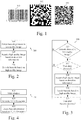
- Figure 1 illustrates some exemplary barcodes.
- the EAN-codes European Article Number codes
- EAN-codes European Article Number codes
- Figure 1 illustrates some exemplary barcodes.
- the EAN-codes European Article Number codes
- EAN-codes may, for example, be scanned at the counter of grocery stores.
- An EAN-code is an example of a one-dimensional barcode.
- An example of a two-dimensional barcode is represented by the exemplary data matrix 102.
- This exemplary data matrix is built up by square modules.
- QR-codes Quadick Response codes
- QR-codes Quad Response codes
- the QR-code is also built up by square modules. In Figure 1 , the modules are depicted as being black or white, but as long as there is acceptable contrast between the colors, any two colors may be used.
- a QR-code is surrounded by a margin, which is commonly referred to as the quiet zone or the safe zone. This margin may be four modules wide.
- QR-codes are widely used in Japan.
- Barcodes may be read by optical scanners, such as laser-equipped scanners for EAN-codes, or scanned from an image by special software adapted to read barcodes of a particular type.
- acquisition of the image that is used for barcode reading can be divided into user assisted image acquisition and automatic image acquisition.
- the user In user assisted image acquisition, the user must perform some kind of action, for example pressing a key or button (take a snapshot), in order to capture the image containing the barcode.
- Some kind of action for example pressing a key or button (take a snapshot)
- the requirement of user action makes such systems less user-friendly.
- the user In a typical situation, the user must hold the object with the barcode on with one hand, hold the phone/camera that is used to capture the image with the other hand and then press a small button on the phone/camera. This may be rather cumbersome.
- the act of pressing of the snapshot button may in itself create motion blur in the captured image, since the camera might be moved slightly when pressing the button.
- an image acquisition system may continually capture images and process them in order to read barcodes.
- the user no longer has to press a button or key, which makes the system more user-friendly.
- requiring the capturing of a continuous stream of images implies other disadvantages. For example, it is not possible to use advanced image capturing features such as flash and/or auto-focus. Hence, the quality of automatically acquired images may be lower than user assisted acquired images.
- a method of retrieving information comprised in a barcode comprises detecting that the barcode is present in a first image having a first image quality and capturing a first region, acquiring, when it is detected that the barcode is present, a second image having a second image quality and capturing a second region, and decoding the barcode based on the second image to retrieve the information.
- the second image quality is higher than the first image quality, and the second region at least partly overlaps the first region.
- the barcode may be a one-dimensional barcode, and in some embodiments, the barcode may be a two-dimensional barcode.
- the first image may be an image of an image stream
- the second image may be a snapshot image
- the first image quality may have a first resolution
- the second image quality may have a second resolution and the first resolution may be lower than the second resolution
- the acquiring step may comprise applying an auto-focus function. In some embodiments, the acquiring step may comprise illuminating the barcode.
- the second region may be equal to the first region in some embodiments, and in some embodiments the second region may be a part if the first region.
- the detecting step may be activated without user interaction.
- the detecting step may be iterated continuously and may further comprise generating a user alert when it is detected that the barcode is present.
- the detecting step, the acquiring step and the decoding step may be activated without user interaction and the method may further comprise generating a user alert when the barcode has been decoded.
- the method may further comprise using the information to look up further information on an Internet server.
- the detection step may comprise sliding a window having a first window size over the first image, wherein the first window size is smaller than the first region, generating YUV-histograms - luma and chrominance histograms - for one or more window positions, and evaluating, for one or more window positions, the corresponding YUV-histograms to determine of the barcode is present at the window position.
- the evaluation step may be performed by a support vector machine algorithm.
- the first image may be represented by a first image signal
- the detection step may comprise applying one or more gradient filters to the first image signal to produce one or more gradient filtered signals, applying one or more dilation filters to the one or more gradient filtered signals to produce one or more dilation filtered signals, applying one or more erosion filters to the one or more dilation filtered signals to produce one or more erosion-filtered signals, finding closed areas in the one or more erosion filtered signals, and calculating, for at least one closed area, corresponding centre of gravity coordinates.
- the corresponding centre of gravity coordinates may be calculated for all closed areas with a size that is greater than a threshold.
- the method may, in some embodiments, further comprise calculating, for at least one closed area, a corresponding side length.
- the method may further comprise creating at least one sub-image based on the at least the closed area and the corresponding centre of gravity coordinates, applying an erosion filter to the at least one sub-image to produce at least one erosion filtered sub-image, detecting edges in the at least one erosion filtered sub-image, transforming the at least one erosion filtered sub-image to a Hough domain, and extracting one or more squares from the at least Hough domain sub-image.
- the method may further comprise verifying the one or more extracted squares based on the detected edges.
- the step of detecting edges may be performed by a Canny edge detector algorithm.
- a computer program product comprises a computer readable medium, having thereon a computer program comprising program instructions.
- the computer program is loadable into a data-processing unit and adapted to cause the data-processing unit to execute method steps according the first aspect of the invention when the computer program is run by the data-processing unit.
- an arrangement comprising an image-acquiring device adapted to acquire the first and second images according to the first aspect of the invention, and logic adapted to perform at least the detecting and decoding steps according the first aspect of the invention.
- the image-acquiring device is a digital camera.
- a communication device which comprises the arrangement according to the third aspect of the invention.
- Another advantage of embodiments of the invention is that barcode information may be reliably read.
- Another advantage of embodiments of the invention is that barcode information may be read in a user-friendly way.
- Another advantage of embodiments of the invention is that a barcode may be detected in an image having a quality that is not suitable for barcode decoding.
- Detection of a barcode and possibly its position may be forwarded to the decoding algorithm. This additional information may speed up the decoding process and thus the entire barcode reading process.
- a low quality image may be used to determine or detect whether or not a barcode is present in the image.
- the image may for example be an image of an image stream that is fed from a camera to a display.
- the image quality may not be good enough for actual barcode decoding to be possible.
- the algorithms used in this step do not try to retrieve any information from the barcode.
- the algorithms used in this step do not even try to localize certain patterns of the barcode (such as the "position patterns” or "finding patterns” of a QR-code). Instead, these embodiments focus on finding an entire barcode based on general code features.
- an image of higher quality may be acquired if it is determined, based on the low quality image, that a barcode is present. This step may or may not involve user action.
- This higher quality image may be acquired as a snapshot of a camera device.
- the higher quality image may be acquired using quality-enhancing features, such as auto-focus, flash, lamp or other illumination features and/or using higher resolution than the low quality image.
- the higher quality image may cover the same or a different image area than the lower quality image used in the determining step. In some embodiments, the higher quality image covers only the region where the barcode, as detected in the previous step, is found (either exactly or a slightly larger region).
- the higher quality image is used to decode the barcode information. Since the image used in the decoding is of a higher quality, there is a better chance of decoding the bar code correctly than if the lower quality image would have been used in the decoding.
- the entire process may be fully automatic. In such embodiments no user action is required, and the cumbersome process described above in connection with user assisted image acquisition is avoided. On the other hand, high quality images can be acquired, which avoids the problems described above with regard to automatic image acquisition.
- the barcode reader may be running in the background without the user even noticing it.
- the barcode reader may be turned on as soon as the user uses the camera (e.g. removes the lens cover or activates a camera menu).
- the first step is running in the background and the user is alerted when a barcode is detected.
- the user may be asked by a prompt whether or not it is desirable to decode the detected barcode.
- all of the three steps are running in the background and the user is not alerted until a successful barcode decoding has been performed.
- FIG. 2 is a flowchart illustrating an example of a method 200 according to some embodiments of the invention.
- step 210 it is detected whether a barcode is present in a low quality image.
- step 220 an image of higher quality is acquired when a barcode is detected.
- step 230 the higher quality image is used to decode the detected barcode.
- FIG. 3 is a flowchart illustrating an example method 300 according to some embodiments of the invention.
- step 310 it is detected whether a barcode is present in a low quality image.
- the detecting step is running continuously (NO-path out of step 310) as described above, possibly without user interaction.
- step 315 When a barcode is detected (YES-path out of step 310) the process proceeds to optional step 315, where a user alert informs the user that a barcode was detected and possibly asks the user if it is desirable to retrieve the barcode information. If the user does not wish to retrieve the barcode information (NO-path out of step 315), the process returns to step 310. If, however, the user wishes to retrieve the barcode information (YES-path out of step 315), the process proceeds to step 320.
- step 320 an image of higher quality is acquired, and the process proceeds to step 330.
- step 330 the higher quality image is used to decode the detected barcode, and the process proceeds to optional step 335; where a user is informed that a barcode has been successfully decoded and is possibly given the barcode information.
- Such a robust detection algorithm uses a detector that searches for rectangular regions in an image.
- a detector may be designed to be much more robust than a barcode reading software (e.g. a barcode decoding algorithm). Since, for example, a QR-code is necessarily a rectangle, it may be sufficient to look for rectangular structures in the low quality image to be able to detect a barcode. When such a structure is found, a higher quality image is acquired and decoded (using a different algorithm than in the detecting step) as explained above.
- the detection step may comprise extracting features from a histogram associated with a barcode. Instead of looking for e.g. the "finding patterns" of a QR-code, the whole code is taken into consideration. Some of these embodiments may use a support vector machine in the detection step.
- An image of a QR-code may generate distinguishing YUV-histograms (luma and chrominance histograms). Properties from these histograms may be used as features for detecting the presence of a barcode.
- the histograms are evaluated, and if the average luminance (Y-component) is in the center of the spectrum (meaning that the luminance variance is large and no color is under- or overrepresented), then a determination may be made that the image shows, for example, a QR-code.
- a histogram does not contain information regarding pixel position.
- some embodiments use a window that is slid over the image. Then some embodiments use a SVM (support vector machine) to evaluate, for each position of the window, whether the window is positioned over a barcode or not. Some embodiments determine that a barcode is present if an area of the image is filled with pixels that are noted as possible barcode pixels by the SVM.
- Some embodiments of the invention process the resulting binary image (comprising pixels that either are or are not possible barcode pixels) further.
- the binary image may be processed by erosion filters and minimum size conditions may be applied to separate actual barcodes.
- Figure 4 is a flowchart illustrating an example method 400 according to some embodiments of the invention.
- the method 400 may, for example, be performed as part of method step 210 or 310 of Figures 2 and 3 respectively.
- a window is slid over the image to be analyzed.
- the window may be slid over the entire image or over only a part of the image.
- YUV-histograms are generated for each or some of the window positions.
- it is evaluated for each or some of the window positions where a YUV-histogram was generated whether this window position represents a possible barcode pixel (in some embodiments; a group of possible barcode pixels).
- steps 410, 420 and 430 may be performed iteratively (e.g. performing all steps for one window position, then all steps for the next window position, etc.) or in sequence (e.g. first performing step 410 for all window positions, then 420 for all window positions, etc.).
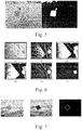
- Figure 5 demonstrates a result obtained by using some embodiments of the invention.
- the left image shows the original image, and the right image shows the resulting binary image after a window has been slid over the image and YUV-histograms have been generated and evaluated.
- the example algorithm described in connection to Figure 4 aims at finding areas that vary substantially between black and white.
- An alternative approach may be to look for high gradients in the image.
- Some embodiments employing this alternative focus on features of the code structure, and explore the intensity contrast between pixels in a code.
- a highly varying intensity may imply a large gradient magnitude, which may indicate the presence of a barcode.
- Some of these embodiments use gradient filters and closing filters.
- the barcode area contains pixels with high intensity differences between each other, which should result in large gradients.
- areas comprising many pixels with a large gradient magnitude are assumed to imply that the area is a barcode, such as a QR-code.
- QR-code example it can also be noted that such a barcode has gradients in all directions.
- Some embodiments take advantage of this property.
- Some embodiments that use the gradient properties aim at providing a fast method that gives an indication of the location and size of a possible barcode. According to some embodiments, this indication may be used in more complex methods that distinguish true barcode indications from false alarms.
- some embodiments that use the gradient properties aim at providing a method that has a low probability of a missed barcode and leaves it to the more complex subsequent method to determine which indications are actually true barcodes.
- Some embodiments focus on separating the environment from the barcode by applying four gradient filters in four different directions and combining the result.
- An algorithm may be provided that applies a Sobel gradient filter in four different directions and creates four gradient images. These images may be turned into binary images using a threshold value. The binary images may be processed with closing filters and then combined into a result image, for example using a logical AND operation.
- Some embodiments define all closed areas in the result image as barcodes. In some embodiments, the closed area has to be larger than a predefined threshold to be defined as a barcode.
- Figure 6 demonstrates that a QR-code gives rise to high gradients in all four directions, while other image material is unlikely to do so.
- (a) is the original image
- (b), (c), (d) and (e) demonstrate the gradient images for the four different directions
- (f) demonstrates the result after performing a logical AND operation between (b), (c), (d) and (e).
- the algorithm according to gradient-exploring embodiments may not only present a barcode position but also the approximate barcode size.
- An advantage of some of these embodiments is that the algorithm is not depending on one threshold, a solution that may be quite sensitive (e.g. making it hard to find the right threshold and making the threshold heavily associated with the data set used to train the algorithm), but instead depends on many thresholds, which makes the algorithm more stable and robust.
- some embodiments handle this by applying a closing filter to each gradient image.
- the closing filter may be designed to fill out gaps in the barcode and the filter design may also consider the width of the quiet zone.
- four different closing filters, one for each gradient image are used. Some embodiments close the gradient image that evaluates the horizontal gradient more in the horizontal direction than in the vertical direction. Thus, the quiet zone in the horizontal direction stays untouched. A similar closing operation may be performed for the other gradient images before combining them.
- the quiet zone has a higher probability of being preserved intact, and that the gradient threshold can be set with even less precision than in the case with an ordinary, rectangular or square shaped closing filter.
- the gradient-evaluating embodiments thus described may be used alone to locate a barcode.
- the output from these algorithms may be viewed as a first step in detecting barcodes.
- the result may be further evaluated to avoid a large amount of false alarms.
- the output may be an approval or a rejection of an area defined by the gradient method.
- Some embodiments extract barcodes from images using its shape (e.g. a square) as the main property.
- Some embodiments use an erosion filter, a Canny edge detector, the Hough transform and some basic algebra.
- the regions defined by the gradient method are further evaluated such that if a sub-image centered at the position returned from the gradient method portrays a square with roughly the same size as that concluded by the gradient method, then that area is classified as a barcode.
- the evaluation may employ a Hough transform.
- the computational complexity of the Hough transform increases with a required high detection accuracy and with the size of the detection range.
- limiting the range by using the information from the gradient method regarding barcode size and position decreases the computational complexity.
- the method is divided into three parts: preprocessing (where the contrast of the barcode is enhanced), square finding, and square verification.
- preprocessing where the contrast of the barcode is enhanced
- square finding may reduce detection errors.
- square verification may reduce detection errors.
- this method may aim at preserving a low probability of a miss and, in addition, at getting a low probability of false alarms.
- edge detection it may be important for successful square detection of, for example, a QR-code to have a good contrast between the quiet zone and the actual barcode. If edge detection is used directly, there is a risk that a square relating to a barcode may not be properly closed and also that there may be many edges found within the barcode square.
- some embodiments may use an erosion filter before applying the edge detection to avoid edges inside the code.
- Figure 7 demonstrates an example result of such embodiments.
- the left image is the original image
- the middle image is the result of the erosion filtering
- the right image is the result of applying an edge detector (Canny edge detector) to the erosion-filtered image.
- the erosion filter may be designed to account for the width of the quiet zone.
- a square search may be performed.
- a method of extracting squares from images as proposed in C. R. Jung and R. Schramm, "Rectangle Detection based on a Windowed Hough Transform", Brazilian Symposium on Computer Graphics and Image Processing, 2004 may be used in the square finding step. For each pixel in an edge image, a sub-window covering a certain neighborhood is applied and the Hough transform for lines is computed for the sub-window. By analyzing the Hough transform image, squares (or rectangles) may be found. According to some embodiments, the Hough transform only has to be applied to image parts where it is probable (based on the output from the gradient method) that a barcode is located.
- the square search may be implemented as a full search where all peaks are tested against the others without symmetry concern.
- the square search may be carried out in one Hough image for the entire preprocessed image instead of in one Hough image for each pixel and the complexity may be reduced.
- a square When a square is found in Hough space it may be validated according to some embodiments of the invention.
- the square validation may be carried out against the binary edge image.
- the square validation may result in that the number of false alarms is further reduced. If all sides of a square that was found in the Hough image can be verified in the binary edge image, then the square may be approved according to some embodiments.
- Figure 8 demonstrates the edge extraction and square finding for an example image.
- the left image is the original image
- the middle image is the result of the edge extraction
- the right image shows the square found through the Hough transform overlaid on the result of the edge extraction.
- Figure 9 is a flowchart illustrating a method 900 according to some embodiments of the invention.
- the method 900 may, for example, be performed as part of method step 210 or 310 of Figures 2 and 3 respectively.
- step 910 one or more gradient filters are applied to an image (possibly in several directions), and in step 920 a closing filter is applied to the result of step 910.
- the closing filter may comprise a dilation filter and an erosion filter as illustrated by sub-steps 921 and 922.
- step 930 closed areas are found in the image resulting from step 920. This may comprise applying a logical AND operation to the filtered images as explained above. In optional step 935, all found closed areas that are smaller than a threshold may be removed. Then, the center of gravity and side length of each of the remaining closed areas are calculated in steps 940 and 950 respectively.
- the side length may, for example, be calculated as the square root of the number of pixels in the area.
- Steps 910 through 950 represent the gradient method as elaborated on previously.
- the method may end in step 950 and the result may be used when performing steps 220 or 320 of Figures 2 and 3 respectively.
- step 950 is also optional. If the side length is not calculated the entire image area or a sub-image area of predefined size and centered at the center of gravity may, for example, be used when performing steps 220 or 320.
- step 960 where one or more sub-images are extracted from the original image based on the information found in steps 940 and 950.
- each of the sub-images are preprocessed to detect edges comprised in the sub-images.
- the preprocessing may comprise applying an erosion filter and an edge-detecting algorithm (such as a Canny edge detector) as illustrated by sub-steps 971 and 972.
- the process continues to step 980, where squares are found in the resulting sub-images output from step 970.
- the square finding may comprise applying a Hough transform and analyzing the result to extract squares as illustrated by sub-steps 981 and 982.
- step 980 The method may end in step 980 and the result may be used when performing steps 220 or 320 of Figures 2 and 3 respectively.
- the method proceeds to step 990, where the squares found in step 980 are verified with the edges found in step 970. If it is determined that a found square does not have corresponding edges to a sufficient degree, then the found square may be rejected.
- Steps 960 through 990 represent the square-finding method as elaborated on previously.
- Embodiments of the invention have been described that, by using a simple filter-based method (such as the gradient method) in a step of identifying barcode candidates and then validating the identified areas with a square finding method, can obtain fast and accurate barcode detection results.
- a simple filter-based method such as the gradient method
- Optimal parameter setting may vary depending on the application and may, for example, be found through training data and simulations. Further, different parameter settings may be applied depending on the requirements on the probabilities of a miss and false alarm respectively.
- Figure 10 illustrates an example mobile terminal 1010 comprising arrangements according to embodiments of the invention.
- the mobile terminal 1010 may be connected, through a radio link, to a base station site.
- the mobile terminal 1010 is illustrated as a mobile telephone in a schematic front view.
- This example mobile terminal 1010 comprises an antenna 1011 mounted on the housing of the apparatus.
- the mobile terminal 1010 may have an internal antenna mounted within the housing of the apparatus.
- the mobile terminal 1010 may even comprise multiple antennas.
- the mobile terminal 1010 may further comprise a display, a keypad, a loudspeaker, and a microphone, which together provides a man-machine interface for operating the mobile terminal 1010.
- the mobile terminal further comprises an image-acquiring device 1012, such as a camera.
- the example mobile terminal 1010 may be adapted to connect to a mobile telecommunication network via the wireless link to a radio base station.
- a user of the mobile terminal 1010 may use conventional circuit-switched telecommunication services such as voice calls, data calls, video calls, and fax transmissions, and/or packet-based services such as electronic messaging, VoIP, Internet browsing, electronic commerce, etc.
- the mobile terminal 1010 and the base station may be compliant with at least one mobile telecommunication standard, for instance UMTS (Universal Mobile Telecommunication System) or UMTS LTE (UMTS Long Term Evolution).
- a connection to a mobile communication network may provide the possibility to use decoded barcode information to look up further information (e.g. relating to a product or an event) on an Internet server accessible via the mobile communication network.
- DSP digital signal processors
- CPU central processing units
- ASIC application-specific integrated circuits
- the invention may be embodied within an electronic apparatus comprising circuitry/logic or performing methods according to any of the embodiments of the invention.
- the electronic apparatus may, for example, be a portable or handheld mobile radio communication equipment, a mobile radio terminal, a mobile telephone, a communicator, an electronic organizer, a smartphone, a digital camera, a barcode scanner, a computer, a mobile gaming device, or a (wrist) watch.
- a computer program product comprises a computer readable medium such as, for example, a diskette or a CD-ROM.
- the computer readable medium may have stored thereon a computer program comprising program instructions.
- the computer program may be loadable into a data-processing unit, which may, for example, be comprised in a mobile terminal. When loaded into the data-processing unit, the computer program may be stored in a memory associated with or integral to the data-processing unit.
- the computer program may, when loaded into and run by the data-processing unit, cause the data-processing unit to execute method steps according to, for example, the methods shown in any of the Figures 2-4 or 9 .
Claims (28)
- Procédé d'extraction d'informations comprises dans un code-barres, comprenant de :détecter (210, 310) si ou non le code-barres est présent dans une première image, la première image étant acquise par un dispositif d'acquisition d'image, ayant une première qualité d'image et capturant une première région, dans lequel l'étape de détection est itérée en continu ;acquérir (220, 320) par le dispositif d'acquisition d'image, quand il est détecté que le code-barres est présent, une seconde image ayant une seconde qualité d'image et capturant une seconde région, dans lequel la seconde qualité d'image est plus haute que la première qualité d'image, et dans lequel la seconde région se superpose au moins partiellement à la première région ; etdécoder (230, 330) le code-barres sur la base de la seconde image pour extraire l'information.
- Procédé selon la revendication 1, dans lequel le code-barres est un code-barres monodimensionnel.
- Procédé selon la revendication 1, dans lequel le code-barres est un code-barres bidimensionnel.
- Procédé selon une quelconque des revendications 1 à 3, dans lequel la première image est une image d'un flux d'images.
- Procédé selon une quelconque des revendications 1 à 4, dans lequel la seconde image est une image d'instanané.
- Procédé selon une quelconque des revendications 1 à 5, dans lequel la première qualité d'image a une première résolution, la seconde qualité d'image a une seconde résolution et la première résolution est inférieure à la seconde résolution.
- Procédé selon une quelconque des revendications 1 à 6, dans lequel l'étape d'acquisition comprend d'appliquer une fonction autofocus.
- Procédé selon une quelconque des revendications 1 à 7, dans lequel l'étape d'acquisition comprend d'illuminer le code-barres.
- Procédé selon une quelconque des revendications 1 à 8, dans lequel la seconde région est égale à la première région.
- Procédé selon une quelconque des revendications 1 à 8, dans lequel la seconde région est une partie de la première région.
- Procédé selon une quelconque des revendications 1 à 10, dans lequel au moins l'étape de détection est activée sans interaction d'utilisateur.
- Procédé selon la revendication 11, comprenant en outre de générer (315) une alerte d'utilisateur quand il est détecté que le code-barres est présent.
- Procédé selon la revendication 11, dans lequel l'étape de détection, l'étape d'acquisition et l'étape de décodage sont activées sans interaction d'utilisateur et comprenant en outre de générer (335) une alerte d'utilisateur lorsque le code-barres a été décodé.
- Procédé selon une quelconque des revendications 1 à 13, comprenant en outre d'utiliser l'information pour rechercher une information supplémentaire sur un serveur Internet.
- Procédé selon une quelconque des revendications 1 à 14, dans lequel l'étape de détection comprend de :faire glisser (410) une fenêtre ayant une première taille de fenêtre sur la première image, dans lequel la première taille de fenêtre est plus petite que la première région ;générer (420) des histogrammes YUV, luma et de chrominance pour une ou plusieurs positions de fenêtre ; etévaluer (430), pour une ou plusieurs positions de fenêtre, les histogrammes YUV correspondants pour déterminer si le code-barres est présent à la position de fenêtre.
- Procédé selon la revendication 15, dans lequel l'étape d'évaluation est effectuée par un algorithme de machine à vecteur de support.
- Procédé selon une quelconque des revendications 1 à 14, dans lequel la première image est représentée par un premier signal d'image, et l'étape de détection comprend de :appliquer (910) un ou plusieurs filtres de gradient au premier signal d'image pour produire un ou plusieurs signaux filtrés de gradient ;appliquer (921) un ou plusieurs filtres de dilatation au ou aux signaux filtrés de gradient pour produire un ou plusieurs signaux filtrés de dilatation ;appliquer (922) un ou plusieurs filtres d'érosion au ou aux signaux filtrés de dilatation pour produire un ou plusieurs signaux filtrés d'érosion ;trouver (930) des zones fermées dans le ou les signaux filtrés d'érosion ; etcalculer (940), pour au moins une zone fermée, des coordonnées de centre de gravité correspondantes.
- Procédé selon la revendication 17, dans lequel le ou les filtres de gradient comprennent deux ou plus filtres de gradient dans des directions différentes.
- Procédé selon la revendication 17, dans lequel le ou les filtres de gradient comprennent quatre filtres de gradient dans quatre directions différentes.
- Procédé selon la revendication 17, dans lequel les coordonnées de centre de gravité correspondantes sont calculées pour toutes les zones fermées avec une taille qui est supérieure à un seuil.
- Procédé selon une quelconque des revendications 16 à 17, comprenant en outre de calculer (950), pour au moins une zone fermée, une longueur latérale correspondante.
- Procédé selon une quelconque des revendications 17 à 21, comprenant en outre de :créer (960) au moins une sous-image sur la base d'au moins la zone fermée et les coordonnées de centre de gravité correspondantes ;appliquer (971) un filtre d'érosion à au moins une sous-image pour produire au moins une sous-image filtrée d'érosion ;détecter (972) des bords dans au moins une sous-image filtrée d'érosion ;transformer (981) au moins une sous-image filtrée d'érosion en un domaine de Hough ; etextraire (982) un ou plusieurs carrés d'au moins une sous-image de domaine de Hough.
- Procédé selon la revendication 22, comprenant en outre de vérifier (990) le ou les carrés extraits sur la base des bords détectés.
- Procédé selon une quelconque des revendications 22 à 23, dans lequel l'étape de détection des bords est effectuée par un algorithme de détecteur de bord Canny.
- Produit de programme informatique comprenant un support lisible par ordinateur, renfermant un programme informatique comprenant des instructions de programme, le programme informatique étant chargeable dans une unité de traitement de données et adapté pour amener l'unité de traitement de données à exécuter les étapes de procédé selon une quelconque des revendications 1 à 24 lorsque le programme informatique est exécuté par l'unité de traitement de données.
- Agencement comprenant :un dispositif d'acquisition d'image (1012) adapté pour acquérir la première et seconde images selon une quelconque des revendications 1 à 24 ; etune logique adaptée pour effectuer au moins les étapes de détection et décodage selon une quelconque des revendications 1 à 24.
- Agencement selon la revendication 26, dans lequel le dispositif d'acquisition d'image est une caméra numérique.
- Dispositif de communication (1010) comprenant l'agencement selon une quelconque des revendications 26 à 27.
Priority Applications (3)
| Application Number | Priority Date | Filing Date | Title |
|---|---|---|---|
| US12/918,378 US8494268B2 (en) | 2008-02-25 | 2009-02-24 | Method and arrangement for retrieving information comprised in a barcode |
| JP2010547197A JP5318122B2 (ja) | 2008-02-25 | 2009-02-24 | バーコードに含まれている情報を読み出す方法及び装置 |
| PCT/EP2009/052150 WO2009106518A1 (fr) | 2008-02-25 | 2009-02-24 | Procédé et agencement pour récupérer des informations comprises dans un code à barres |
Applications Claiming Priority (1)
| Application Number | Priority Date | Filing Date | Title |
|---|---|---|---|
| US3118608P | 2008-02-25 | 2008-02-25 |
Publications (2)
| Publication Number | Publication Date |
|---|---|
| EP2093697A1 EP2093697A1 (fr) | 2009-08-26 |
| EP2093697B1 true EP2093697B1 (fr) | 2017-08-23 |
Family
ID=40612893
Family Applications (1)
| Application Number | Title | Priority Date | Filing Date |
|---|---|---|---|
| EP08153834.0A Active EP2093697B1 (fr) | 2008-02-25 | 2008-03-31 | Procédé et agencement pour récupérer des informations contenues dans un code-barres |
Country Status (4)
| Country | Link |
|---|---|
| US (2) | US8494268B2 (fr) |
| EP (1) | EP2093697B1 (fr) |
| JP (1) | JP5318122B2 (fr) |
| WO (1) | WO2009106518A1 (fr) |
Families Citing this family (34)
| Publication number | Priority date | Publication date | Assignee | Title |
|---|---|---|---|---|
| US20110135144A1 (en) * | 2009-07-01 | 2011-06-09 | Hand Held Products, Inc. | Method and system for collecting voice and image data on a remote device and coverting the combined data |
| JP4971483B2 (ja) | 2010-05-14 | 2012-07-11 | 任天堂株式会社 | 画像表示プログラム、画像表示装置、画像表示システム、および画像表示方法 |
| EP2395474A3 (fr) | 2010-06-11 | 2014-03-26 | Nintendo Co., Ltd. | Support de stockage doté d'un programme de reconnaissance d'images stocké sur celui-ci, appareil de reconnaissance d'images, système de reconnaissance d'images et procédé de reconnaissance d'images |
| US8313030B2 (en) * | 2010-11-11 | 2012-11-20 | Psion Inc. | System and method for barcode scanning with color image sensors |
| US8584953B2 (en) | 2011-02-24 | 2013-11-19 | Psion, Inc. | System and method for decoding barcodes not easily perceptible by human vision |
| US8500023B2 (en) | 2011-02-24 | 2013-08-06 | Psion Inc. | System and method for providing sufficient illumination quality for barcodes captured with a color image sensor |
| US8079525B1 (en) * | 2011-02-24 | 2011-12-20 | Psion Inc. | System and method for decoding barcodes captured with a color image sensor |
| US9100576B2 (en) | 2011-12-05 | 2015-08-04 | Xerox Corporation | Camera positioning tool for symbology reading |
| US8867857B2 (en) | 2011-12-28 | 2014-10-21 | Samsung Electronics Co., Ltd. | Method for restoration of blurred barcode images |
| US8763908B1 (en) * | 2012-03-27 | 2014-07-01 | A9.Com, Inc. | Detecting objects in images using image gradients |
| US9111258B2 (en) * | 2012-10-25 | 2015-08-18 | Microsoft Technology Licensing, Llc | Connecting to meetings with barcodes or other watermarks on meeting content |
| US9807263B2 (en) | 2012-10-31 | 2017-10-31 | Conduent Business Services, Llc | Mobile document capture assistance using augmented reality |
| US9600703B2 (en) * | 2013-03-15 | 2017-03-21 | Cognex Corporation | Systems and methods for sorting image acquisition settings for pattern stitching and decoding using multiple captured images |
| CN105359165B (zh) * | 2013-06-28 | 2018-01-26 | 柯达阿拉里斯股份有限公司 | 确定文档中的条形码位置 |
| MX2017001811A (es) | 2014-08-08 | 2017-07-17 | Georgia Pacific Consumer Products Lp | Dispensadores de producto de hoja y metodos relacionados para reducir el uso del producto de hoja. |
| JP6455832B2 (ja) * | 2014-12-02 | 2019-01-23 | インターナショナル・ビジネス・マシーンズ・コーポレーションInternational Business Machines Corporation | バーコード検出方法、バーコード検出システムおよびそのためのプログラム |
| CN105991999B (zh) * | 2015-02-15 | 2019-12-24 | 联想(北京)有限公司 | 信息处理方法及电子设备 |
| JP6352875B2 (ja) | 2015-09-11 | 2018-07-04 | 株式会社東芝 | マーカ生成方法、マーカ復号方法、マーカ復号装置およびマーカ読取装置 |
| US10628736B2 (en) | 2015-09-24 | 2020-04-21 | Huron Technologies International Inc. | Systems and methods for barcode annotations for digital images |
| KR101807566B1 (ko) | 2016-06-17 | 2017-12-11 | 인천대학교 산학협력단 | 바코드 검출 방법 및 장치 |
| CN106039332A (zh) * | 2016-07-30 | 2016-10-26 | 山东中保康医疗器具有限公司 | 病毒灭活添加、过滤检视方法及系统 |
| US11367092B2 (en) * | 2017-05-01 | 2022-06-21 | Symbol Technologies, Llc | Method and apparatus for extracting and processing price text from an image set |
| US20180314908A1 (en) * | 2017-05-01 | 2018-11-01 | Symbol Technologies, Llc | Method and apparatus for label detection |
| US11042772B2 (en) | 2018-03-29 | 2021-06-22 | Huron Technologies International Inc. | Methods of generating an encoded representation of an image and systems of operating thereof |
| ES2848842T3 (es) | 2018-05-15 | 2021-08-12 | Wooptix S L | Método de detección de código de barras |
| JP2020064373A (ja) | 2018-10-15 | 2020-04-23 | 富士通株式会社 | コード情報読取装置、方法、及びプログラム |
| JP2020064374A (ja) | 2018-10-15 | 2020-04-23 | 富士通株式会社 | コード情報読取装置、方法、及びプログラム |
| US11941478B2 (en) | 2018-10-19 | 2024-03-26 | Diagnostics Instruments, Inc. | Barcode scanning of bulk sample containers |
| US11054431B2 (en) | 2018-10-19 | 2021-07-06 | Diagnostic Instruments, Inc. | Barcode scanning of bulk sample containers |
| CA3118014A1 (fr) | 2018-11-05 | 2020-05-14 | Hamid Reza Tizhoosh | Systemes et procedes de gestion d'images medicales |
| US10762317B2 (en) * | 2018-11-06 | 2020-09-01 | International Business Machines Corporation | Quick response (QR) code deformation |
| US11620806B2 (en) * | 2019-06-07 | 2023-04-04 | Qualcomm Incorporated | Optical character detection using a low-power sensor |
| EP4252190A1 (fr) | 2020-11-24 | 2023-10-04 | Huron Technologies International Inc. | Systèmes et procédés de génération de représentations codées pour de multiples grossissements de données d'image |
| CN113962976B (zh) * | 2021-01-20 | 2022-09-16 | 赛维森(广州)医疗科技服务有限公司 | 用于病理玻片数字图像的质量评估方法 |
Family Cites Families (19)
| Publication number | Priority date | Publication date | Assignee | Title |
|---|---|---|---|---|
| US5262871A (en) * | 1989-11-13 | 1993-11-16 | Rutgers, The State University | Multiple resolution image sensor |
| US5487115A (en) * | 1992-05-14 | 1996-01-23 | United Parcel Service | Method and apparatus for determining the fine angular orientation of bar code symbols in two-dimensional CCD images |
| JPH07143335A (ja) | 1993-11-18 | 1995-06-02 | Fuji Xerox Co Ltd | カラー複写機における複写禁止原稿複写防止装置及び方法 |
| US5504319A (en) * | 1994-02-09 | 1996-04-02 | Symbol Technologies, Inc. | Method and system for bar code acquisition |
| US5784102A (en) * | 1995-05-15 | 1998-07-21 | Welch Allyn, Inc. | Optical reader having improved interactive image sensing and control circuitry |
| JPH1038542A (ja) | 1996-07-19 | 1998-02-13 | Tsubakimoto Chain Co | 物体認識方法及び装置並びに記録媒体 |
| US6082619A (en) | 1998-12-16 | 2000-07-04 | Matsushita Electric Industrial Co., Ltd. | Method for locating and reading a two-dimensional barcode |
| TW419634B (en) * | 1999-02-02 | 2001-01-21 | Ind Tech Res Inst | Automatic detection system and method using bar code positioning |
| US6688525B1 (en) * | 1999-09-22 | 2004-02-10 | Eastman Kodak Company | Apparatus and method for reading a coded pattern |
| US6695209B1 (en) * | 1999-10-04 | 2004-02-24 | Psc Scanning, Inc. | Triggerless optical reader with signal enhancement features |
| US6941026B1 (en) * | 2000-06-13 | 2005-09-06 | Cognex Corporation | Method and apparatus using intensity gradients for visual identification of 2D matrix symbols |
| US7268924B2 (en) * | 2001-01-22 | 2007-09-11 | Hand Held Products, Inc. | Optical reader having reduced parameter determination delay |
| JP2003203198A (ja) | 2002-01-08 | 2003-07-18 | Canon Inc | 撮像装置、撮像方法、コンピュータ読み取り可能な記憶媒体及びコンピュータプログラム |
| US6993573B2 (en) * | 2003-06-06 | 2006-01-31 | Neomedia Technologies, Inc. | Automatic access of internet content with a camera-enabled cell phone |
| FI20040858A (fi) * | 2004-06-18 | 2005-12-19 | Valtion Teknillinen | Menetelmä koodin tunnistamiseksi matkaviestimen avulla ja matkaviestin |
| US20060011724A1 (en) * | 2004-07-15 | 2006-01-19 | Eugene Joseph | Optical code reading system and method using a variable resolution imaging sensor |
| US20070069028A1 (en) * | 2004-12-10 | 2007-03-29 | Yaron Nemet | System to improve reading performance and accuracy of single or two dimensional data codes in a large field of view |
| US8150163B2 (en) * | 2006-04-12 | 2012-04-03 | Scanbuy, Inc. | System and method for recovering image detail from multiple image frames in real-time |
| TWI479428B (zh) * | 2008-10-14 | 2015-04-01 | Sicpa Holding Sa | 用於物品識別之方法及系統 |
-
2008
- 2008-03-31 EP EP08153834.0A patent/EP2093697B1/fr active Active
-
2009
- 2009-02-24 JP JP2010547197A patent/JP5318122B2/ja not_active Expired - Fee Related
- 2009-02-24 WO PCT/EP2009/052150 patent/WO2009106518A1/fr active Application Filing
- 2009-02-24 US US12/918,378 patent/US8494268B2/en active Active
-
2013
- 2013-06-19 US US13/921,571 patent/US8774453B2/en active Active
Also Published As
| Publication number | Publication date |
|---|---|
| JP2011513809A (ja) | 2011-04-28 |
| EP2093697A1 (fr) | 2009-08-26 |
| US20130292473A1 (en) | 2013-11-07 |
| US20110007967A1 (en) | 2011-01-13 |
| US8494268B2 (en) | 2013-07-23 |
| US8774453B2 (en) | 2014-07-08 |
| WO2009106518A1 (fr) | 2009-09-03 |
| JP5318122B2 (ja) | 2013-10-16 |
Similar Documents
| Publication | Publication Date | Title |
|---|---|---|
| EP2093697B1 (fr) | Procédé et agencement pour récupérer des informations contenues dans un code-barres | |
| EP2221746B1 (fr) | Appareil et procédé pour améliorer la capacité de reconnaissance de texte | |
| EP2650821B1 (fr) | Procédé de rognure d'image de texte | |
| EP1434164A2 (fr) | Procédé d'extraction d'une région de dents d'une image dentaire et procédé et appareil d'identification de personnes avec cette image | |
| US10540532B2 (en) | System and method for detecting optical codes with damaged or incomplete finder patterns | |
| EP2974261A2 (fr) | Systèmes et procédés pour classifier des objets dans des images numériques capturées à l'aide de dispositifs mobiles | |
| WO2013044875A1 (fr) | Procédé et système d'identification de code barres linéaire | |
| Chen et al. | A two-stage quality measure for mobile phone captured 2D barcode images | |
| US20200302135A1 (en) | Method and apparatus for localization of one-dimensional barcodes | |
| KR20180111639A (ko) | 정보 처리 장치, 그의 제어 방법, 및 기억 매체 | |
| JP6630341B2 (ja) | シンボルの光学的検出方法 | |
| CN108108646B (zh) | 条码信息识别方法、终端和计算机可读存储介质 | |
| CN111178347B (zh) | 证件图像的模糊度检测方法、装置、设备及存储介质 | |
| CN110610178A (zh) | 图像识别方法、装置、终端及计算机可读存储介质 | |
| Gallo et al. | Reading challenging barcodes with cameras | |
| CN108769521B (zh) | 一种拍照方法、移动终端及计算机可读存储介质 | |
| CN106557766B (zh) | 模糊字符处理方法、系统及电子设备 | |
| WO2017219562A1 (fr) | Procédé et appareil permettant de générer un code bidimensionnel | |
| JP5220482B2 (ja) | 対象物検出装置及びプログラム | |
| KR20150130253A (ko) | 정보 유출 방지를 위한 이미지 적응적 비정형 개인 정보 추출 방법 및 이를 수행하는 장치 | |
| CN110543799A (zh) | 二维码处理方法、装置、存储介质与移动终端 | |
| CN107113380B (zh) | 一种计算系统、方法和机器可读非暂时性存储介质 | |
| CN112329572B (zh) | 一种基于边框和闪光点的快速静态活体检测方法及装置 | |
| Chen et al. | Video-based content recognition of bank cards with mobile devices | |
| Xiao et al. | A new binarization method for PDF417 bar code by camera phone |
Legal Events
| Date | Code | Title | Description |
|---|---|---|---|
| PUAI | Public reference made under article 153(3) epc to a published international application that has entered the european phase |
Free format text: ORIGINAL CODE: 0009012 |
|
| AK | Designated contracting states |
Kind code of ref document: A1 Designated state(s): AT BE BG CH CY CZ DE DK EE ES FI FR GB GR HR HU IE IS IT LI LT LU LV MC MT NL NO PL PT RO SE SI SK TR |
|
| AX | Request for extension of the european patent |
Extension state: AL BA MK RS |
|
| 17P | Request for examination filed |
Effective date: 20091208 |
|
| AKX | Designation fees paid |
Designated state(s): AT BE BG CH CY CZ DE DK EE ES FI FR GB GR HR HU IE IS IT LI LT LU LV MC MT NL NO PL PT RO SE SI SK TR |
|
| GRAP | Despatch of communication of intention to grant a patent |
Free format text: ORIGINAL CODE: EPIDOSNIGR1 |
|
| INTG | Intention to grant announced |
Effective date: 20161123 |
|
| GRAS | Grant fee paid |
Free format text: ORIGINAL CODE: EPIDOSNIGR3 |
|
| GRAA | (expected) grant |
Free format text: ORIGINAL CODE: 0009210 |
|
| AK | Designated contracting states |
Kind code of ref document: B1 Designated state(s): AT BE BG CH CY CZ DE DK EE ES FI FR GB GR HR HU IE IS IT LI LT LU LV MC MT NL NO PL PT RO SE SI SK TR |
|
| REG | Reference to a national code |
Ref country code: GB Ref legal event code: FG4D |
|
| REG | Reference to a national code |
Ref country code: CH Ref legal event code: EP |
|
| REG | Reference to a national code |
Ref country code: AT Ref legal event code: REF Ref document number: 922082 Country of ref document: AT Kind code of ref document: T Effective date: 20170915 |
|
| REG | Reference to a national code |
Ref country code: IE Ref legal event code: FG4D |
|
| REG | Reference to a national code |
Ref country code: DE Ref legal event code: R096 Ref document number: 602008051721 Country of ref document: DE |
|
| REG | Reference to a national code |
Ref country code: NL Ref legal event code: MP Effective date: 20170823 |
|
| REG | Reference to a national code |
Ref country code: LT Ref legal event code: MG4D |
|
| REG | Reference to a national code |
Ref country code: AT Ref legal event code: MK05 Ref document number: 922082 Country of ref document: AT Kind code of ref document: T Effective date: 20170823 |
|
| PG25 | Lapsed in a contracting state [announced via postgrant information from national office to epo] |
Ref country code: NO Free format text: LAPSE BECAUSE OF FAILURE TO SUBMIT A TRANSLATION OF THE DESCRIPTION OR TO PAY THE FEE WITHIN THE PRESCRIBED TIME-LIMIT Effective date: 20171123 Ref country code: HR Free format text: LAPSE BECAUSE OF FAILURE TO SUBMIT A TRANSLATION OF THE DESCRIPTION OR TO PAY THE FEE WITHIN THE PRESCRIBED TIME-LIMIT Effective date: 20170823 Ref country code: FI Free format text: LAPSE BECAUSE OF FAILURE TO SUBMIT A TRANSLATION OF THE DESCRIPTION OR TO PAY THE FEE WITHIN THE PRESCRIBED TIME-LIMIT Effective date: 20170823 Ref country code: SE Free format text: LAPSE BECAUSE OF FAILURE TO SUBMIT A TRANSLATION OF THE DESCRIPTION OR TO PAY THE FEE WITHIN THE PRESCRIBED TIME-LIMIT Effective date: 20170823 Ref country code: NL Free format text: LAPSE BECAUSE OF FAILURE TO SUBMIT A TRANSLATION OF THE DESCRIPTION OR TO PAY THE FEE WITHIN THE PRESCRIBED TIME-LIMIT Effective date: 20170823 Ref country code: LT Free format text: LAPSE BECAUSE OF FAILURE TO SUBMIT A TRANSLATION OF THE DESCRIPTION OR TO PAY THE FEE WITHIN THE PRESCRIBED TIME-LIMIT Effective date: 20170823 Ref country code: AT Free format text: LAPSE BECAUSE OF FAILURE TO SUBMIT A TRANSLATION OF THE DESCRIPTION OR TO PAY THE FEE WITHIN THE PRESCRIBED TIME-LIMIT Effective date: 20170823 |
|
| PG25 | Lapsed in a contracting state [announced via postgrant information from national office to epo] |
Ref country code: PL Free format text: LAPSE BECAUSE OF FAILURE TO SUBMIT A TRANSLATION OF THE DESCRIPTION OR TO PAY THE FEE WITHIN THE PRESCRIBED TIME-LIMIT Effective date: 20170823 Ref country code: LV Free format text: LAPSE BECAUSE OF FAILURE TO SUBMIT A TRANSLATION OF THE DESCRIPTION OR TO PAY THE FEE WITHIN THE PRESCRIBED TIME-LIMIT Effective date: 20170823 Ref country code: GR Free format text: LAPSE BECAUSE OF FAILURE TO SUBMIT A TRANSLATION OF THE DESCRIPTION OR TO PAY THE FEE WITHIN THE PRESCRIBED TIME-LIMIT Effective date: 20171124 Ref country code: ES Free format text: LAPSE BECAUSE OF FAILURE TO SUBMIT A TRANSLATION OF THE DESCRIPTION OR TO PAY THE FEE WITHIN THE PRESCRIBED TIME-LIMIT Effective date: 20170823 Ref country code: BG Free format text: LAPSE BECAUSE OF FAILURE TO SUBMIT A TRANSLATION OF THE DESCRIPTION OR TO PAY THE FEE WITHIN THE PRESCRIBED TIME-LIMIT Effective date: 20171123 Ref country code: IS Free format text: LAPSE BECAUSE OF FAILURE TO SUBMIT A TRANSLATION OF THE DESCRIPTION OR TO PAY THE FEE WITHIN THE PRESCRIBED TIME-LIMIT Effective date: 20171223 |
|
| REG | Reference to a national code |
Ref country code: FR Ref legal event code: PLFP Year of fee payment: 11 |
|
| PG25 | Lapsed in a contracting state [announced via postgrant information from national office to epo] |
Ref country code: DK Free format text: LAPSE BECAUSE OF FAILURE TO SUBMIT A TRANSLATION OF THE DESCRIPTION OR TO PAY THE FEE WITHIN THE PRESCRIBED TIME-LIMIT Effective date: 20170823 Ref country code: CZ Free format text: LAPSE BECAUSE OF FAILURE TO SUBMIT A TRANSLATION OF THE DESCRIPTION OR TO PAY THE FEE WITHIN THE PRESCRIBED TIME-LIMIT Effective date: 20170823 Ref country code: RO Free format text: LAPSE BECAUSE OF FAILURE TO SUBMIT A TRANSLATION OF THE DESCRIPTION OR TO PAY THE FEE WITHIN THE PRESCRIBED TIME-LIMIT Effective date: 20170823 |
|
| REG | Reference to a national code |
Ref country code: DE Ref legal event code: R097 Ref document number: 602008051721 Country of ref document: DE |
|
| PG25 | Lapsed in a contracting state [announced via postgrant information from national office to epo] |
Ref country code: IT Free format text: LAPSE BECAUSE OF FAILURE TO SUBMIT A TRANSLATION OF THE DESCRIPTION OR TO PAY THE FEE WITHIN THE PRESCRIBED TIME-LIMIT Effective date: 20170823 Ref country code: SK Free format text: LAPSE BECAUSE OF FAILURE TO SUBMIT A TRANSLATION OF THE DESCRIPTION OR TO PAY THE FEE WITHIN THE PRESCRIBED TIME-LIMIT Effective date: 20170823 Ref country code: EE Free format text: LAPSE BECAUSE OF FAILURE TO SUBMIT A TRANSLATION OF THE DESCRIPTION OR TO PAY THE FEE WITHIN THE PRESCRIBED TIME-LIMIT Effective date: 20170823 |
|
| PLBE | No opposition filed within time limit |
Free format text: ORIGINAL CODE: 0009261 |
|
| STAA | Information on the status of an ep patent application or granted ep patent |
Free format text: STATUS: NO OPPOSITION FILED WITHIN TIME LIMIT |
|
| 26N | No opposition filed |
Effective date: 20180524 |
|
| PG25 | Lapsed in a contracting state [announced via postgrant information from national office to epo] |
Ref country code: SI Free format text: LAPSE BECAUSE OF FAILURE TO SUBMIT A TRANSLATION OF THE DESCRIPTION OR TO PAY THE FEE WITHIN THE PRESCRIBED TIME-LIMIT Effective date: 20170823 |
|
| REG | Reference to a national code |
Ref country code: CH Ref legal event code: PL |
|
| PG25 | Lapsed in a contracting state [announced via postgrant information from national office to epo] |
Ref country code: MC Free format text: LAPSE BECAUSE OF FAILURE TO SUBMIT A TRANSLATION OF THE DESCRIPTION OR TO PAY THE FEE WITHIN THE PRESCRIBED TIME-LIMIT Effective date: 20170823 |
|
| REG | Reference to a national code |
Ref country code: BE Ref legal event code: MM Effective date: 20180331 |
|
| REG | Reference to a national code |
Ref country code: IE Ref legal event code: MM4A |
|
| PG25 | Lapsed in a contracting state [announced via postgrant information from national office to epo] |
Ref country code: LU Free format text: LAPSE BECAUSE OF NON-PAYMENT OF DUE FEES Effective date: 20180331 |
|
| PG25 | Lapsed in a contracting state [announced via postgrant information from national office to epo] |
Ref country code: IE Free format text: LAPSE BECAUSE OF NON-PAYMENT OF DUE FEES Effective date: 20180331 |
|
| PG25 | Lapsed in a contracting state [announced via postgrant information from national office to epo] |
Ref country code: LI Free format text: LAPSE BECAUSE OF NON-PAYMENT OF DUE FEES Effective date: 20180331 Ref country code: CH Free format text: LAPSE BECAUSE OF NON-PAYMENT OF DUE FEES Effective date: 20180331 Ref country code: BE Free format text: LAPSE BECAUSE OF NON-PAYMENT OF DUE FEES Effective date: 20180331 |
|
| PG25 | Lapsed in a contracting state [announced via postgrant information from national office to epo] |
Ref country code: MT Free format text: LAPSE BECAUSE OF NON-PAYMENT OF DUE FEES Effective date: 20180331 |
|
| PG25 | Lapsed in a contracting state [announced via postgrant information from national office to epo] |
Ref country code: TR Free format text: LAPSE BECAUSE OF FAILURE TO SUBMIT A TRANSLATION OF THE DESCRIPTION OR TO PAY THE FEE WITHIN THE PRESCRIBED TIME-LIMIT Effective date: 20170823 |
|
| PG25 | Lapsed in a contracting state [announced via postgrant information from national office to epo] |
Ref country code: PT Free format text: LAPSE BECAUSE OF FAILURE TO SUBMIT A TRANSLATION OF THE DESCRIPTION OR TO PAY THE FEE WITHIN THE PRESCRIBED TIME-LIMIT Effective date: 20170823 Ref country code: HU Free format text: LAPSE BECAUSE OF FAILURE TO SUBMIT A TRANSLATION OF THE DESCRIPTION OR TO PAY THE FEE WITHIN THE PRESCRIBED TIME-LIMIT; INVALID AB INITIO Effective date: 20080331 |
|
| PG25 | Lapsed in a contracting state [announced via postgrant information from national office to epo] |
Ref country code: CY Free format text: LAPSE BECAUSE OF FAILURE TO SUBMIT A TRANSLATION OF THE DESCRIPTION OR TO PAY THE FEE WITHIN THE PRESCRIBED TIME-LIMIT Effective date: 20170823 |
|
| PGFP | Annual fee paid to national office [announced via postgrant information from national office to epo] |
Ref country code: FR Payment date: 20230327 Year of fee payment: 16 |
|
| P01 | Opt-out of the competence of the unified patent court (upc) registered |
Effective date: 20230523 |
|
| PGFP | Annual fee paid to national office [announced via postgrant information from national office to epo] |
Ref country code: DE Payment date: 20240327 Year of fee payment: 17 Ref country code: GB Payment date: 20240327 Year of fee payment: 17 |