EP0784745B1 - Systeme electronique de commande de moteur a combustion interne - Google Patents
Systeme electronique de commande de moteur a combustion interne Download PDFInfo
- Publication number
- EP0784745B1 EP0784745B1 EP96908000A EP96908000A EP0784745B1 EP 0784745 B1 EP0784745 B1 EP 0784745B1 EP 96908000 A EP96908000 A EP 96908000A EP 96908000 A EP96908000 A EP 96908000A EP 0784745 B1 EP0784745 B1 EP 0784745B1
- Authority
- EP
- European Patent Office
- Prior art keywords
- internal combustion
- combustion engine
- control system
- electronic control
- ignition
- Prior art date
- Legal status (The legal status is an assumption and is not a legal conclusion. Google has not performed a legal analysis and makes no representation as to the accuracy of the status listed.)
- Expired - Lifetime
Links
Images
Classifications
-
- F—MECHANICAL ENGINEERING; LIGHTING; HEATING; WEAPONS; BLASTING
- F02—COMBUSTION ENGINES; HOT-GAS OR COMBUSTION-PRODUCT ENGINE PLANTS
- F02D—CONTROLLING COMBUSTION ENGINES
- F02D41/00—Electrical control of supply of combustible mixture or its constituents
- F02D41/02—Circuit arrangements for generating control signals
- F02D41/04—Introducing corrections for particular operating conditions
- F02D41/042—Introducing corrections for particular operating conditions for stopping the engine
-
- F—MECHANICAL ENGINEERING; LIGHTING; HEATING; WEAPONS; BLASTING
- F02—COMBUSTION ENGINES; HOT-GAS OR COMBUSTION-PRODUCT ENGINE PLANTS
- F02D—CONTROLLING COMBUSTION ENGINES
- F02D41/00—Electrical control of supply of combustible mixture or its constituents
- F02D41/009—Electrical control of supply of combustible mixture or its constituents using means for generating position or synchronisation signals
-
- F—MECHANICAL ENGINEERING; LIGHTING; HEATING; WEAPONS; BLASTING
- F02—COMBUSTION ENGINES; HOT-GAS OR COMBUSTION-PRODUCT ENGINE PLANTS
- F02D—CONTROLLING COMBUSTION ENGINES
- F02D41/00—Electrical control of supply of combustible mixture or its constituents
- F02D41/02—Circuit arrangements for generating control signals
- F02D41/04—Introducing corrections for particular operating conditions
- F02D41/06—Introducing corrections for particular operating conditions for engine starting or warming up
- F02D41/062—Introducing corrections for particular operating conditions for engine starting or warming up for starting
-
- F—MECHANICAL ENGINEERING; LIGHTING; HEATING; WEAPONS; BLASTING
- F02—COMBUSTION ENGINES; HOT-GAS OR COMBUSTION-PRODUCT ENGINE PLANTS
- F02N—STARTING OF COMBUSTION ENGINES; STARTING AIDS FOR SUCH ENGINES, NOT OTHERWISE PROVIDED FOR
- F02N99/00—Subject matter not provided for in other groups of this subclass
- F02N99/002—Starting combustion engines by ignition means
- F02N99/006—Providing a combustible mixture inside the cylinder
-
- F—MECHANICAL ENGINEERING; LIGHTING; HEATING; WEAPONS; BLASTING
- F02—COMBUSTION ENGINES; HOT-GAS OR COMBUSTION-PRODUCT ENGINE PLANTS
- F02D—CONTROLLING COMBUSTION ENGINES
- F02D41/00—Electrical control of supply of combustible mixture or its constituents
- F02D41/009—Electrical control of supply of combustible mixture or its constituents using means for generating position or synchronisation signals
- F02D2041/0092—Synchronisation of the cylinders at engine start
-
- F—MECHANICAL ENGINEERING; LIGHTING; HEATING; WEAPONS; BLASTING
- F02—COMBUSTION ENGINES; HOT-GAS OR COMBUSTION-PRODUCT ENGINE PLANTS
- F02D—CONTROLLING COMBUSTION ENGINES
- F02D41/00—Electrical control of supply of combustible mixture or its constituents
- F02D41/009—Electrical control of supply of combustible mixture or its constituents using means for generating position or synchronisation signals
- F02D2041/0095—Synchronisation of the cylinders during engine shutdown
-
- F—MECHANICAL ENGINEERING; LIGHTING; HEATING; WEAPONS; BLASTING
- F02—COMBUSTION ENGINES; HOT-GAS OR COMBUSTION-PRODUCT ENGINE PLANTS
- F02D—CONTROLLING COMBUSTION ENGINES
- F02D41/00—Electrical control of supply of combustible mixture or its constituents
- F02D41/0097—Electrical control of supply of combustible mixture or its constituents using means for generating speed signals
Definitions
- the invention is based on an electronic control system for an internal combustion engine according to the preamble of the main claim.
- Such an encoder system is, for example, from the DE-OS 43 04 163 known.
- the encoder system described there is used in a device for controlling the Fuel injection in an internal combustion engine if possible quickly after starting the engine to generate correct injection pulses so that a faster Speed ramp is possible.
- the electronic control system for a Internal combustion engine with the features of claim 1 Advantage that a compared to the known facilities further reduction of the start time is possible. Achieved is this advantage by in the control unit of the internal combustion engine the position of the internal combustion engine, i.e. the Angular position of the crankshaft and / or camshaft and the cylinder position is determined until the time at which all Waves have stopped. Just before this Standstill occurs, i.e. at a time when the Speed of the internal combustion engine a predeterminable value, the is also referred to as the minimum speed, at least one additional injection is triggered. This injection takes place in an inlet valve that shortly before the internal combustion engine comes to a standstill is.
- Another advantage of the invention is that it can be used in all internal combustion engines that either have an absolute angle encoder system that immediately provides a clear signal after switching on or the carry out a run-out detection, the standstill position immediately after switching on again.
- the electronic Control system related to an internal combustion engine can be used with start / stop systems.
- the internal combustion engine to save fuel independently under specified conditions off and on again.
- the control unit is not switched off and detects whether one of the Shafts of internal combustion engines has rotated.
- An automatic start / stop is usually between the ignition and the stop and start of the internal combustion engine (KL15) not switched off.
- the restart can be done without actuation the starter, it is also possible the starter to operate and additionally with the injection according to the invention to support the starter to get a quick one To achieve speed ramp-up.
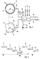
- Figure 1 which is largely known from DE-OS 43 04 163 is necessary to explain the invention
- Components of an internal combustion engine shown as an example 10 denotes an encoder disk, which rigidly connected to the crankshaft 11 of the internal combustion engine is and on its circumference a variety of similar angle marks 12 has.
- a reference mark 13 which is exemplary is realized by two missing angle marks.
- a second encoder disk 14 is connected to the camshaft 15 Internal combustion engine connected and has on its circumference Segment 16 or possibly further segments 16a, b, c of different lengths with which the phase position the reference mark on the crankshaft pulley becomes.
- At 17 is the existing between the crankshaft and camshaft Connection that the crankshaft at half crankshaft speed turns, symbolizes. From knowledge of the angular position the crankshaft or camshaft can be known the position of the internal combustion engine, for example what the cylinder position is or which intake valves are open or closed.
- the two encoder disks 10, 14 are supported by sensors 18, 19 scanned when the angle marks pass in the Signals generated by sensors become, for example, square-wave signals processed and evaluated in the control unit 20. From the chronological sequence of the individual edges of the square-wave signals both the speed and the information with regard to the angular positions of the crankshaft or camshaft win.
- the control unit 20 receives further, via various inputs, for the control or regulation of the internal combustion engine required input quantities from corresponding sensors 21, 22, 23 can be measured.
- an "ignition on” signal is input 24 supplied that when the ignition switch 25 is closed by the Terminal KL15 of the ignition lock is supplied. Via clamp KL15 can also be connected to the starter of the internal combustion engine actuate.
- control unit 20 does not provide this computing or storage means shown and one with 30 designated permanent memory includes, signals for the ignition and injection for unspecified corresponding ones Components of the internal combustion engine are available. These signals are via the outputs 26 and 27 of the control unit 20 delivered.
- the control unit 20 is supplied with voltage in usually with the help of a battery 28, which has a Switch 29 during operation of the internal combustion engine as well as during a run-on phase after the engine has been switched off is connected to the control unit 20.
- a boundary condition for restarting for example be provided that after a gas request, that is, after the accelerator pedal is actuated, the internal combustion engine is started again. Since in automatic start / stop between Stop and start of the engine the ignition lock KL15 usually not switched off, the start can be very done quickly.
- a possible course of action by the electronic control system can be represented as follows: If the control unit 20 detects that the internal combustion engine corresponding control pulses are to be switched off generates a shutdown of injection and / or ignition cause, there are no more burns and the engine is turned off. As a result of her However, indolence turns for a while, during this time there is a leak detection, while in the control unit the angular positions of Crankshaft and / or camshaft as well as the cylinder positions be determined. Furthermore, speed measurements are also carried out carried out. This leakage detection ultimately provides the parking position of the internal combustion engine or Motors.
- the speed signals in the shutdown phase are as Reverse angle included in the starting position. Is in during the shutdown phase an inadmissible twisting of the engine, for example recognized across a compression point, the following start algorithm is prohibited. Is one Rotation direction detection before, the rotation angle during the parking position included in the starting position.
- control unit 20 requests "engine start” recognized, is in the cylinder or cylinders, the one or the other after the compression point (ZOT), an ignition is issued.
- This ignition ignites that due to the last one Flammable injections prior to standstill Air-fuel mixture. This will start the engine to turn immediately. After the next cylinder the ZOT has reached an ignition in this cylinder too triggered.
- the position of the internal combustion engine continue by means of the known starting position and the Encoder signals determined during start-up. A additional support for the rotary movement by the starter the internal combustion engine is possible.
- Engine start begins like that from DE-OS 43 04 163 known device for controlling the fuel injection injection in an internal combustion engine. It can be referred to as zero or first splashes Injections take place. After the synchronization, so after the reference mark has been recognized by the control unit to one of the well-known controls for ignition and injection (For example, sequential fuel injection SEFI).
- the described electronic control system can be used with all Internal combustion engines are used, the appropriate encoder systems have, for example, with incremental encoder systems with or without phase encoder or with segment systems with encoder on the crankshaft and / or camshaft as well as brands in the area of the ignition OT.
- FIG 2 is an example of a four-cylinder engine the relationship between injection and ignition in the shutdown phase, in the shutdown position of the internal combustion engine and the start phase, with the shutdown phase with Ab, the start phase with St and the engine shutdown position are designated with MA.
- MA Areas of intake valves E1 to E4 that correspond to the corresponding Cylinders are assigned, open.
- In the intake valves E2 and E3 are injected when turned off, which are designated with A1A or A2A.
- In the intake valve E4 is an injection before the start of rotation Internal combustion engine sold. This injection is called Zero splash N designated. Once the engine has started rotating Injections labeled EEE. These injections may take place before synchronization.
- Z0 to ZX are ignitions in the individual cylinders.
- Z0 denotes the ignition of the when it is turned off injected fuel (ignition according to ZOT).
- Z1 designated the ignition of the fuel injected when switching off (Regular ignition).
- Z2 to Z4 the ignitions are then remaining cylinders designated when starting with fuel be supplied. The following applies with regard to the cylinder position: With the A1A injection, the cylinder is still at the start before top dead center (ZOT), so there is still one "regular" ignition possible. At injection A2A stands the cylinder when restarting after ZOT.
Landscapes
- Engineering & Computer Science (AREA)
- Chemical & Material Sciences (AREA)
- Combustion & Propulsion (AREA)
- Mechanical Engineering (AREA)
- General Engineering & Computer Science (AREA)
- Combined Controls Of Internal Combustion Engines (AREA)
- Output Control And Ontrol Of Special Type Engine (AREA)
- Electrical Control Of Air Or Fuel Supplied To Internal-Combustion Engine (AREA)
Claims (8)
- Système de commande électronique d'un moteur à combustion interne comprenant une installation de calcul qui détermine et exploite la position angulaire du vilebrequin et/ou de l'arbre à cames et fournit ainsi les positions de cylindre ou la position du moteur à combustion interne ainsi que la vitesse de rotation par des signaux donnés par des capteurs, pour former des signaux de commande d'injection de carburant et/ou d'allumage, l'installation de calcul comprenant des moyens qui reconnaissent la phase de coupure du moteur à combustion interne et interrompent l'injection de carburant et/ou d'allumage et en phase de coupure, lorsque la vitesse de rotation diminue, on continue de déterminer la position du moteur à combustion interne jusqu'à déceler la position d'arrêt,
caractérisé en ce qu'
en cas de dépassement vers le bas d'une vitesse de rotation minimale au moins une injection supplémentaire dans l'un des cylindres qui ne peuvent plus être alimentés en carburant probablement lors du nouveau démarrage parce que les soupapes d'admission sont déjà fermées, mais qui se trouvent encore dans la période de combustion ou doivent atteindre cette période est ainsi déclenchée. - Système de commande électronique selon la revendication 1,
caractérisé en ce que
les injections en phase d'arrêt se font également dans les soupapes d'injection, les cylindres étant associés pour qu'a priori, lors du démarrage suivant, ils se trouvent déjà dans une position avec un point mort haut d'allumage mais ne fournissent toutefois pas encore de participation au couple. - Système de commande électronique selon la revendication 1 ou 2 ,
caractérisé en ce que
l'installation de calcul est l'appareil de commande du moteur à combustion interne qui détermine la position d'arrêt prévisible avant que l'arrêt ne se produise effectivement. - Système de commande électronique selon l'une quelconque des revendications précédentes
caractérisé en ce qu'
on détermine en continu le gradient de la vitesse de rotation et on fixe la vitesse de rotation minimale en fonction du gradient de vitesse de rotation. - Système de commande électronique selon l'une quelconque des revendications 1, 2, 3,
caractérisé en ce que
dès que l'appareil de commande reconnaít une demande de démarrage pour le moteur à combustion interne, dans le cylindre dans lequel du carburant a continué d'être injecté avant la coupure du moteur, on déclenche l'allumage. - Système de commande électronique selon l'une des revendications précédentes,
caractérisé en ce qu'
après le début de la rotation, mais avant la synchronisation, on déclenche d'autres injections et/ou allumages et les cylindres correspondants sont déterminés par l'appareil de commande en tenant compte de la position d'arrêt mise en mémoire pour le moteur à combustion interne. - Système de commande électronique selon l'une quelconque des revendications précédentes,
caractérisé en ce que
les capteurs déterminant la position angulaire du vilebrequin et/ou de l'arbre à cames sont des capteurs absolus ou effectuant une reconnaissance de fin de course et mettant en mémoire les positions angulaires dans la position d'arrêt. - Système de commande électronique selon l'une des revendications précédentes,
caractérisé en ce qu'
il est utilisé en liaison avec des systèmes automatiques démarrage/arrêt.
Applications Claiming Priority (3)
| Application Number | Priority Date | Filing Date | Title |
|---|---|---|---|
| DE19527503 | 1995-07-27 | ||
| DE1995127503 DE19527503A1 (de) | 1995-07-27 | 1995-07-27 | Elektronisches Steuersystem für eine Brennkraftmaschine |
| PCT/DE1996/000584 WO1997005372A1 (fr) | 1995-07-27 | 1996-04-03 | Systeme electronique de commande de moteur a combustion interne |
Publications (2)
| Publication Number | Publication Date |
|---|---|
| EP0784745A1 EP0784745A1 (fr) | 1997-07-23 |
| EP0784745B1 true EP0784745B1 (fr) | 1999-01-27 |
Family
ID=7767956
Family Applications (1)
| Application Number | Title | Priority Date | Filing Date |
|---|---|---|---|
| EP96908000A Expired - Lifetime EP0784745B1 (fr) | 1995-07-27 | 1996-04-03 | Systeme electronique de commande de moteur a combustion interne |
Country Status (4)
| Country | Link |
|---|---|
| EP (1) | EP0784745B1 (fr) |
| JP (1) | JP3957752B2 (fr) |
| DE (2) | DE19527503A1 (fr) |
| WO (1) | WO1997005372A1 (fr) |
Families Citing this family (25)
| Publication number | Priority date | Publication date | Assignee | Title |
|---|---|---|---|---|
| DE19705340C1 (de) * | 1997-02-12 | 1998-08-13 | Siemens Ag | Verfahren und Vorrichtung zum Ansteuern einer Brennkraftmaschine |
| DE19852228A1 (de) * | 1998-11-12 | 2000-05-18 | Bayerische Motoren Werke Ag | Verfahren und Vorrichtung zum kontrollierten Abstellen eines Verbrennungsmotors |
| SE522243C2 (sv) | 1998-11-19 | 2004-01-27 | Scania Cv Ab | Anordning vid förbränningsmotorer |
| FR2827911B1 (fr) * | 2001-07-27 | 2004-01-30 | Peugeot Citroen Automobiles Sa | Procede de reglage de l'arret et procede de redemarrage d'un moteur a combustion interne |
| JP3571014B2 (ja) * | 2001-08-30 | 2004-09-29 | 本田技研工業株式会社 | 内燃機関の自動停止始動制御装置 |
| LU90909B1 (en) * | 2002-04-16 | 2003-10-17 | Delphi Tech Inc | Method for operating an engine providing improved starting characteristics |
| DE10221393B4 (de) * | 2002-05-14 | 2005-12-22 | Siemens Ag | Vorrichtung und Verfahren zum Starten einer mehrzylindrigen Brennkraftmaschine |
| JP3815441B2 (ja) * | 2003-02-04 | 2006-08-30 | トヨタ自動車株式会社 | 内燃機関の停止始動制御装置 |
| JP3941705B2 (ja) * | 2003-02-13 | 2007-07-04 | トヨタ自動車株式会社 | 内燃機関の停止始動制御装置 |
| DE10320046B4 (de) * | 2003-02-27 | 2014-03-20 | Robert Bosch Gmbh | Anordnung zur Bestimmung der Kurbelwellenlage einer mehrzylindrigen Brennkraftmaschine |
| DE10322361A1 (de) * | 2003-05-09 | 2004-11-25 | Robert Bosch Gmbh | Verfahren und Vorrichtung zum Verbessern des Startverhaltens eines Verbrennungsmotors |
| DE10351891B4 (de) | 2003-11-06 | 2017-03-30 | Robert Bosch Gmbh | Verfahren und Steuergerät zum Neustarten einer Brennkraftmaschine |
| DE10360798B3 (de) * | 2003-12-23 | 2005-06-30 | Bayerische Motoren Werke Ag | Verfahren zur Vorbereitung eines Starts einer Brennkraftmaschine |
| JP4345587B2 (ja) * | 2004-06-21 | 2009-10-14 | トヨタ自動車株式会社 | 内燃機関の機関始動制御システム |
| JP4424153B2 (ja) * | 2004-10-22 | 2010-03-03 | トヨタ自動車株式会社 | 内燃機関装置および内燃機関の停止位置推定方法並びに内燃機関の制御方法 |
| JP4385940B2 (ja) * | 2004-11-17 | 2009-12-16 | トヨタ自動車株式会社 | 内燃機関装置およびこれを搭載する自動車並びに内燃機関の運転停止方法 |
| JP4371047B2 (ja) * | 2004-12-08 | 2009-11-25 | トヨタ自動車株式会社 | 内燃機関装置および内燃機関の制御方法 |
| JP4453536B2 (ja) * | 2004-12-10 | 2010-04-21 | トヨタ自動車株式会社 | 駆動装置およびこれを搭載する自動車並びに駆動装置の制御方法 |
| EP1679438A1 (fr) | 2005-01-10 | 2006-07-12 | Ford Global Technologies, LLC, A subsidary of Ford Motor Company | Méthode de démarrage d'un moteur à explosion |
| US7461621B2 (en) | 2005-09-22 | 2008-12-09 | Mazda Motor Corporation | Method of starting spark ignition engine without using starter motor |
| CN101688482B (zh) * | 2008-05-12 | 2012-08-15 | 丰田自动车株式会社 | 内燃机的停止起动控制装置 |
| TWI567293B (zh) * | 2013-07-03 | 2017-01-21 | 山葉發動機股份有限公司 | 引擎系統及跨坐型車輛 |
| US9631575B2 (en) | 2013-07-18 | 2017-04-25 | Ford Global Technologies, Llc | Methods and systems for improving engine starting |
| DE102013221638A1 (de) | 2013-10-24 | 2015-04-30 | Volkswagen Aktiengesellschaft | Nockenwellenanordnung einer Hubkolbenrennkraftmaschine sowie Hubkolbenbrennkraftmaschine mit einer solchen Nockenwellenanordnung |
| JP7310461B2 (ja) * | 2019-09-03 | 2023-07-19 | トヨタ自動車株式会社 | パワートレーンシステム |
Citations (2)
| Publication number | Priority date | Publication date | Assignee | Title |
|---|---|---|---|---|
| US4273089A (en) * | 1979-09-12 | 1981-06-16 | Essex Group, Inc. | Open loop computer-controlled spark ignition timing system |
| US4364343A (en) * | 1981-05-08 | 1982-12-21 | General Motors Corporation | Automatic engine shutdown and restart system |
Family Cites Families (2)
| Publication number | Priority date | Publication date | Assignee | Title |
|---|---|---|---|---|
| IT1184957B (it) * | 1985-06-04 | 1987-10-28 | Weber Spa | Sistema di alimentazione di carburante all avviamento di un motore endotermico comprendente un sistema di iniezione elettronica |
| US4875443A (en) * | 1987-02-17 | 1989-10-24 | Nippondenso Co., Ltd. | Start control system for internal combustion engine |
-
1995
- 1995-07-27 DE DE1995127503 patent/DE19527503A1/de not_active Withdrawn
-
1996
- 1996-04-03 EP EP96908000A patent/EP0784745B1/fr not_active Expired - Lifetime
- 1996-04-03 DE DE59601222T patent/DE59601222D1/de not_active Expired - Lifetime
- 1996-04-03 WO PCT/DE1996/000584 patent/WO1997005372A1/fr active IP Right Grant
- 1996-04-03 JP JP50706197A patent/JP3957752B2/ja not_active Expired - Fee Related
Patent Citations (2)
| Publication number | Priority date | Publication date | Assignee | Title |
|---|---|---|---|---|
| US4273089A (en) * | 1979-09-12 | 1981-06-16 | Essex Group, Inc. | Open loop computer-controlled spark ignition timing system |
| US4364343A (en) * | 1981-05-08 | 1982-12-21 | General Motors Corporation | Automatic engine shutdown and restart system |
Also Published As
| Publication number | Publication date |
|---|---|
| JP3957752B2 (ja) | 2007-08-15 |
| WO1997005372A1 (fr) | 1997-02-13 |
| JPH10506694A (ja) | 1998-06-30 |
| EP0784745A1 (fr) | 1997-07-23 |
| DE19527503A1 (de) | 1997-01-30 |
| DE59601222D1 (de) | 1999-03-11 |
Similar Documents
| Publication | Publication Date | Title |
|---|---|---|
| EP0784745B1 (fr) | Systeme electronique de commande de moteur a combustion interne | |
| EP0683855B1 (fr) | Installation de commande de l'injection de carburant d'un moteur a combustion interne | |
| DE60036034T2 (de) | Steuerapparat, um einen Verbrennungsmotor anzulassen und Kraftstoffnaturermittlungsapparat | |
| DE112005002825B4 (de) | Brennkraftmaschinenanhalte- und -startverfahren | |
| DE19521277A1 (de) | Einrichtung zur Zylindererkennung bei einer mehrzylindrigen Brennkraftmaschine | |
| EP1159527A1 (fr) | Dispositif et procede pour arreter, de maniere controlee, un moteur a combustion interne | |
| WO1998012432A1 (fr) | Procede permettant de determiner l'angle de phase d'un moteur a combustion interne a quatre temps et a nombre impair de cylindres | |
| DE19963516A1 (de) | Steuervorrichtung für einen Antriebsmotor eines Motors | |
| DE10304449B4 (de) | Verfahren zur Steuerung einer direkten Einspitzung einer Brennkraftmaschine | |
| EP0638717B1 (fr) | Dispositif pour commander l'injection en carburant et l'allumage d'un moteur à combustion | |
| EP1045967B1 (fr) | Dispositif de reconnaissance de phase | |
| DE19810214B4 (de) | Verfahren zur Synchronisation einer mehrzylindrigen Brennkraftmaschine | |
| DE4243178A1 (de) | Verfahren zur Erkennung undichter Einspritzventile bei einer Brennkraftmaschine | |
| DE4418579B4 (de) | Einrichtung zur Regelung einer Brennkraftmaschine | |
| DE102017112693A1 (de) | Motor-Stopp-Positionssteuerungssystem und Verfahren | |
| EP0684375A1 (fr) | Dispositif pour la régulation d'un moteur à combustion interne | |
| DE10310365B4 (de) | Steuervorrichtung für einen Verbrennungsmotor | |
| DE102007027709A1 (de) | Verfahren zum Start einer Brennkraftmaschine | |
| EP1457652A2 (fr) | Procédé et dispositif de commande pour commander le fonctionnement marche-arrêt d'un moteur à combustion interne | |
| DE69532493T2 (de) | Synchronisationsvorrichtung ohne Nockenwellenpositionssensor für eine innere Brennkraftmaschine | |
| DE4418578B4 (de) | Einrichtung zur Erkennung der Phasenlage bei einer Brennkraftmaschine | |
| DE19517767C2 (de) | Kraftstoffeinspritz-Steuersystem für eine Brennkraftmaschine | |
| DE102013205023B4 (de) | Verfahren zur steuerung eines nockenwellenphasenstellers | |
| DE10324858B4 (de) | Verfahren zur Rückdreherkennung einer Brennkraftmaschine | |
| DE10320046B4 (de) | Anordnung zur Bestimmung der Kurbelwellenlage einer mehrzylindrigen Brennkraftmaschine |
Legal Events
| Date | Code | Title | Description |
|---|---|---|---|
| PUAI | Public reference made under article 153(3) epc to a published international application that has entered the european phase |
Free format text: ORIGINAL CODE: 0009012 |
|
| AK | Designated contracting states |
Kind code of ref document: A1 Designated state(s): DE FR GB IT |
|
| 17P | Request for examination filed |
Effective date: 19970813 |
|
| GRAG | Despatch of communication of intention to grant |
Free format text: ORIGINAL CODE: EPIDOS AGRA |
|
| 17Q | First examination report despatched |
Effective date: 19980416 |
|
| GRAG | Despatch of communication of intention to grant |
Free format text: ORIGINAL CODE: EPIDOS AGRA |
|
| GRAH | Despatch of communication of intention to grant a patent |
Free format text: ORIGINAL CODE: EPIDOS IGRA |
|
| GRAH | Despatch of communication of intention to grant a patent |
Free format text: ORIGINAL CODE: EPIDOS IGRA |
|
| GRAA | (expected) grant |
Free format text: ORIGINAL CODE: 0009210 |
|
| AK | Designated contracting states |
Kind code of ref document: B1 Designated state(s): DE FR GB IT |
|
| REF | Corresponds to: |
Ref document number: 59601222 Country of ref document: DE Date of ref document: 19990311 |
|
| ET | Fr: translation filed | ||
| ITF | It: translation for a ep patent filed |
Owner name: STUDIO JAUMANN P. & C. S.N.C. |
|
| GBT | Gb: translation of ep patent filed (gb section 77(6)(a)/1977) |
Effective date: 19990330 |
|
| PLBE | No opposition filed within time limit |
Free format text: ORIGINAL CODE: 0009261 |
|
| STAA | Information on the status of an ep patent application or granted ep patent |
Free format text: STATUS: NO OPPOSITION FILED WITHIN TIME LIMIT |
|
| 26N | No opposition filed | ||
| REG | Reference to a national code |
Ref country code: GB Ref legal event code: IF02 |
|
| PGFP | Annual fee paid to national office [announced via postgrant information from national office to epo] |
Ref country code: GB Payment date: 20030324 Year of fee payment: 8 |
|
| PG25 | Lapsed in a contracting state [announced via postgrant information from national office to epo] |
Ref country code: GB Free format text: LAPSE BECAUSE OF NON-PAYMENT OF DUE FEES Effective date: 20040403 |
|
| GBPC | Gb: european patent ceased through non-payment of renewal fee | ||
| PGFP | Annual fee paid to national office [announced via postgrant information from national office to epo] |
Ref country code: FR Payment date: 20120511 Year of fee payment: 17 |
|
| PGFP | Annual fee paid to national office [announced via postgrant information from national office to epo] |
Ref country code: IT Payment date: 20120424 Year of fee payment: 17 |
|
| REG | Reference to a national code |
Ref country code: FR Ref legal event code: ST Effective date: 20131231 |
|
| PG25 | Lapsed in a contracting state [announced via postgrant information from national office to epo] |
Ref country code: FR Free format text: LAPSE BECAUSE OF NON-PAYMENT OF DUE FEES Effective date: 20130430 Ref country code: IT Free format text: LAPSE BECAUSE OF NON-PAYMENT OF DUE FEES Effective date: 20130403 |
|
| PGFP | Annual fee paid to national office [announced via postgrant information from national office to epo] |
Ref country code: DE Payment date: 20140626 Year of fee payment: 19 |
|
| REG | Reference to a national code |
Ref country code: DE Ref legal event code: R119 Ref document number: 59601222 Country of ref document: DE |
|
| PG25 | Lapsed in a contracting state [announced via postgrant information from national office to epo] |
Ref country code: DE Free format text: LAPSE BECAUSE OF NON-PAYMENT OF DUE FEES Effective date: 20151103 |