EP0784254B1 - Vorrichtung zur Regelung des Durchflusses einer Flüssigkeit - Google Patents
Vorrichtung zur Regelung des Durchflusses einer Flüssigkeit Download PDFInfo
- Publication number
- EP0784254B1 EP0784254B1 EP96120467A EP96120467A EP0784254B1 EP 0784254 B1 EP0784254 B1 EP 0784254B1 EP 96120467 A EP96120467 A EP 96120467A EP 96120467 A EP96120467 A EP 96120467A EP 0784254 B1 EP0784254 B1 EP 0784254B1
- Authority
- EP
- European Patent Office
- Prior art keywords
- valve
- wafer crystal
- valve plate
- flow channel
- electrodes
- Prior art date
- Legal status (The legal status is an assumption and is not a legal conclusion. Google has not performed a legal analysis and makes no representation as to the accuracy of the status listed.)
- Expired - Lifetime
Links
Images


Classifications
-
- G—PHYSICS
- G01—MEASURING; TESTING
- G01F—MEASURING VOLUME, VOLUME FLOW, MASS FLOW OR LIQUID LEVEL; METERING BY VOLUME
- G01F23/00—Indicating or measuring liquid level or level of fluent solid material, e.g. indicating in terms of volume or indicating by means of an alarm
- G01F23/0053—Indicating or measuring liquid level or level of fluent solid material, e.g. indicating in terms of volume or indicating by means of an alarm with over-flow pipes
-
- F—MECHANICAL ENGINEERING; LIGHTING; HEATING; WEAPONS; BLASTING
- F15—FLUID-PRESSURE ACTUATORS; HYDRAULICS OR PNEUMATICS IN GENERAL
- F15C—FLUID-CIRCUIT ELEMENTS PREDOMINANTLY USED FOR COMPUTING OR CONTROL PURPOSES
- F15C5/00—Manufacture of fluid circuit elements; Manufacture of assemblages of such elements integrated circuits
-
- F—MECHANICAL ENGINEERING; LIGHTING; HEATING; WEAPONS; BLASTING
- F16—ENGINEERING ELEMENTS AND UNITS; GENERAL MEASURES FOR PRODUCING AND MAINTAINING EFFECTIVE FUNCTIONING OF MACHINES OR INSTALLATIONS; THERMAL INSULATION IN GENERAL
- F16K—VALVES; TAPS; COCKS; ACTUATING-FLOATS; DEVICES FOR VENTING OR AERATING
- F16K31/00—Actuating devices; Operating means; Releasing devices
- F16K31/02—Actuating devices; Operating means; Releasing devices electric; magnetic
-
- G—PHYSICS
- G01—MEASURING; TESTING
- G01F—MEASURING VOLUME, VOLUME FLOW, MASS FLOW OR LIQUID LEVEL; METERING BY VOLUME
- G01F15/00—Details of, or accessories for, apparatus of groups G01F1/00 - G01F13/00 insofar as such details or appliances are not adapted to particular types of such apparatus
- G01F15/005—Valves
-
- G—PHYSICS
- G01—MEASURING; TESTING
- G01F—MEASURING VOLUME, VOLUME FLOW, MASS FLOW OR LIQUID LEVEL; METERING BY VOLUME
- G01F23/00—Indicating or measuring liquid level or level of fluent solid material, e.g. indicating in terms of volume or indicating by means of an alarm
- G01F23/22—Indicating or measuring liquid level or level of fluent solid material, e.g. indicating in terms of volume or indicating by means of an alarm by measuring physical variables, other than linear dimensions, pressure or weight, dependent on the level to be measured, e.g. by difference of heat transfer of steam or water
- G01F23/24—Indicating or measuring liquid level or level of fluent solid material, e.g. indicating in terms of volume or indicating by means of an alarm by measuring physical variables, other than linear dimensions, pressure or weight, dependent on the level to be measured, e.g. by difference of heat transfer of steam or water by measuring variations of resistance of resistors due to contact with conductor fluid
- G01F23/241—Indicating or measuring liquid level or level of fluent solid material, e.g. indicating in terms of volume or indicating by means of an alarm by measuring physical variables, other than linear dimensions, pressure or weight, dependent on the level to be measured, e.g. by difference of heat transfer of steam or water by measuring variations of resistance of resistors due to contact with conductor fluid for discrete levels
Definitions
- the invention relates to a device for regulating the flow a liquid in a capillary dimension Flow channel in the preamble of claim 1 specified type.
- Control loops for such devices basically have a sensor, an electrical or mechanical regulator and an actuator. Because in the regulation of mechanical quantities very different physical effects are used, are the individual components of such control loops usually realized by special discrete assemblies, which too can be interconnected in a control system. Because of the different Requirements and manufacturing methods result comparatively for the manufacture of the complete system high manufacturing costs. Other than that, it can connect technical difficulties of the individual assemblies. Such difficulties can arise with capillaries, for example Flow systems at the transition points of individual channels, which due to higher flow resistance a flow inhibition or even interrupt the river.
- DE 43 05 924 A1 and DE 43 06 061 A1 are specific applications known at which difficulties explained above may occur.
- a liquid, fed from a pressurized reservoir is removed capillary from a nozzle.
- To regulate the Fluid intake becomes necessary by means of a sensor that the liquid level in a capillary buffer or Overflow chamber monitored, determined to match the level regulate the fluid supply by means of a valve.
- Suitable components for this are from the above-mentioned publications known.
- From DE 43 20 715 A1 is also a miniaturized valve known for the above Application is basically suitable.
- the present invention has for its object a Device for controlling the liquid flow with Flow channel, level sensor and valve to create at which the disadvantages explained above are avoided and its Functional components, especially with the smallest dimensions are inexpensive to manufacture. This task is solved with a device of the type specified in claim 1.
- the basic idea of the invention is all functional components in a compact component made of uniform material to unite. Building on that from the references mentioned above known technology is according to the present invention also the valve, consisting of valve plate and valve seat and an electromechanical converter, in this module integrated.
- valve plate is integrated in the carrier plate and with this over a thin-walled, elastically deformable Membrane connected.
- Such a configuration can be most conveniently according to Claim 3 together with the channels and chambers by etching produce.
- the electrodes for the sensor can, however, according to claim 4 deposited in the form of flat conductor tracks on the second carrier plate, e.g. B. evaporated or sputtered.
- etching processes it is suitable for the carrier plate a silicon chip.
- electrodes are also suitable for borosilicate glass, which has a similar expansion coefficient as silicon has and with a silicon chip according to claim 6 in simpler Can be connected by gluing or bonding.
- This transducer which is preferably made of piezoelectric ceramic exists, can be designed as a bending transducer according to claim 8 be.
- valve chamber capillary coupled so that the liquid from the valve chamber transported into the flow channel by capillary forces becomes.
- Optical sensors are generally suitable as sensors DE 43 05 924 A1, capacitive sensors according to DE 43 06 061 A1 and Piezoelectric sensors according to DE 43 16 148 A1.
- the electrical connection of the electrodes are used according to claim 16 contact pads, with which leads preferably are conductively connected by bonding.
- Fluid regulators of the type described here can be particularly advantageous Way using known silicon processing methods getting produced.
- the completed controller modules are expedient mounted on a plastic carrier, e.g. B. using epoxy resin adhesive glued. They can also be overmoulded with plastic or snapped into plastic housing parts.
- the piezoelectric bending transducer is not immediately in one of the carrier plates is integrated, it can be retrofitted by means of a suitable adhesive, e.g. B. a two-component adhesive, be connected to the carrier plate.
- a suitable adhesive e.g. B. a two-component adhesive
- connection block In the same way, one containing electronics Mechanically connect the connection block to the controller module, whereby the electrical connection is made using bonded gold wires can.
- the carrier chip can be made of borosilicate glass (Trade name Pyrexglas) exist. In this case it is anodic bonding makes it easier to connect the chips. This must be in the area of the valve, i.e. the valve plate or the inlet opening, a connection-preventing Layer, e.g. B. a chrome-gold layer to be deposited.
- a connection-preventing Layer e.g. B. a chrome-gold layer to be deposited.
- capillary channels and chambers are incorporated into the carrier plate and without resistance-increasing mechanical joints merge into one another is simple and reliable flow control guaranteed.
- planar surfaces of the chips make it easy Installation of any hybrid or integrated drive, preferably in the form of a piezoelectric one Layer.
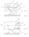
- the channel carrier plate 10 the so-called channel chip, consists of a thin-walled silicon plate into which the flow channel 11, the overflow chamber 12 and an electrode chamber 13 are etched are.
- the Carrier plate 10 on the left in the drawing for production an elastically deformable membrane 14 diluted in the middle an island-like stiffener that acts as a valve plate or valve disk is used.
- the flow channel 11 opens in the area of the membrane 14 and is to the chamber 16, the is formed by membrane 14 electrode support plate 20, capillary coupled.
- the chambers open into the other end of the flow channel 11 12 and 13, the chamber 12 having a first electrode 21 as an overflow chamber and the chamber 13 for receiving the second electrode to serve.
- the electrodes 21 and 22 assigned to these chambers 12 and 13 are designed as conductor tracks. Their contact pad 21a and 22a are located in an area that will be used later Joining the two plates 10 and 20 for contacting of the connecting wires remain free. Furthermore, the electrode carrier plate has the carrier chip 20, inlet and outlet openings 23 and 24 on which the passage channel 11 on the one hand and on the other hand are assigned to the valve plate (15).
- This assignment can be more precisely the representations according to the figure 5 and 6, which remove the completed controller module reveal.
- This consists of the two connected Carrier plates 10 and 20, which both the flow channel 11 and the chambers 12 and 13 limit.
- the assembly passes through the valve opening 23 as far as the valve plate 15 by means of a not shown here Converter raised and thus the valve opened is.
- the liquid collects in the valve chamber 16 and is from this due to capillary forces in the flow channel 11 sucked to the regulator through the outlet opening 24 again to leave.
- the overflow or buffer chamber fills up 12.
- At the end of this chamber is in the form of a conductor track trained electrode 21 provided with the liquid when the overflow chamber 12 is completely filled in galvanic Contact came.
- the second electrode 22 which is arranged in the chamber 13, with the liquid in galvanic contact.
Landscapes
- Engineering & Computer Science (AREA)
- Physics & Mathematics (AREA)
- General Engineering & Computer Science (AREA)
- Fluid Mechanics (AREA)
- General Physics & Mathematics (AREA)
- Mechanical Engineering (AREA)
- Microelectronics & Electronic Packaging (AREA)
- Computer Hardware Design (AREA)
- Theoretical Computer Science (AREA)
- Thermal Sciences (AREA)
- Micromachines (AREA)
- Electrically Driven Valve-Operating Means (AREA)
- Flow Control (AREA)
Description
- Figur 1
- Aufsicht auf die Kanalträgerplatte (Kanalchip),
- Figur 2
- Schnitt längs der Linie II-II in Figur 1,
- Figur 3
- Aufsicht auf die Elektrodenträgerplatte (Trägerchip),
- Figur 4
- Schnitt längs der Linie IV-IV in Figur 3,
- Figur 5
- Aufsicht auf den kompletten Reglerbaustein und
- Figur 6
- Schnitt längs der Linie VI-VI. in Figur 5.
- 1
- Reglerbaustein (Reglermodul)
- 10
- Trägerplatte für Kanäle (Kanalchip)
- 11
- Durchflußkanal
- 12
- Puffer- bzw. Überlaufkammer
- 13
- Elektrodenkammer
- 14
- Ventilmembran
- 15
- Ventilplatte
- 16
- Ventilkammer
- 20
- Trägerplatte für Elektroden (Trägerchip)
- 21, 22
- Elektroden bzw. Leiterbahnen für Elektroden
- 21a, 22a
- Kontaktanschlußflächen
- 23
- Einlaßöffnung als Ventilöffnung und Ventilsitz
- 24
- Auslaßöffnung
Claims (16)
- Vorrichtung zur Regelung des Durchflusses einer Flüssigkeit in einem Ein- und Auslaß aufweisenden Durchflußkanal, bestehend aus einer Überlaufkammer, welche zwischen Ein- und Auslaß fluidmäßig mit dem Durchlaßkanal verbunden ist, einem Sensor mit Elektroden zur Überwachung des Flüssigkeitsstandes in der Überlaufkammer sowie einem elektrisch in Abhängkeit vom Füllstand steuerbaren Ventil, welches den Ein- oder Auslaß sperrt bzw freigibt, dadurch gekennzeichnet, daß der Durchflußkanal (11), die Überlaufkammer (12) und eine auslenkbare Ventilplatte (15) des Ventils in einer ersten Trägerplatte (10) und die Elektroden (21, 22) des Sensors sowie die Ein- und Auslässe (23, 24) in einer zweiten Trägerplatte (20) angeordnet sind, wobei der Ein- bzw. Auslaß (23, 24) den Ventilsitz bildet, daß die beiden Platten (10, 20) miteinander zu einem kompakten Baustein verbunden sind und daß der Ventilplatte (15) ein elektromechanischer Wandler zur Steuerung des Ventils (14, 15, 23) zugeordnet ist.
- Vorrichtung nach Anspruch 1, dadurch gekennzeichnet, daß die Ventilplatte (15) mit der Trägerplatte (10) über eine dünnwandige, elastisch verformbare Membran (14) verbunden ist.
- Vorrichtung nach Anspruch 1 oder 2, dadurch gekennzeichnet, daß mindestens die erste Trägerplatte (10) aus einem Siliziumchip besteht, bei welchem die Kanäle (11) und Kammern (12) sowie die die Ventilplatte (15) tragende Membran (14) durch Ätzen hergestellt sind.
- Vorrichtung nach Anspruch 1, 2 oder 3, dadurch gekennzeichnet, daß die Elektroden (21, 22) in Form ebener Leiterbahnen auf die zweite Trägerplatte (20) aufgedampft oder aufgesputtert sind.
- Vorrichtung nach Anspruch 4, dadurch gekennzeichnet, daß die zweite Trägerplatte (20) aus Silizium bzw. Borosilikatglas besteht.
- Vorrichtung nach einem der Ansprüche 1 bis 5, dadurch gekennzeichnet, daß die Trägerplatten (10, 20) durch Kleben oder Bonden miteinander bleibend verbunden sind.
- Vorrichtung nach einem der Ansprüche 1 bis 6, dadurch gekennzeichnet, daß die die Ventilplatte (15) aufweisende Trägerplatte (10) mit einem piezoelektrischen Wandler zur Auslenkung der Ventilplatte (15) versehen ist.
- Vorrichtung nach Anspruch 7, dadurch gekennzeichnet, daß der vorzugsweise aus Keramik bestehende piezoelektrische Wandler ein Biegewandler ist.
- Vorrichtung nach Anspruch 7 oder 8, dadurch gekennzeichnet, daß der Wandler scheibenförmig ausgebildet und an der Außenseite der die Ventilplatte (15) aufweisenden Trägerplatte (10) vorzugsweise durch Kleben oder Bonden befestigt ist.
- Vorrichtung nach einem der Ansprüche 1 bis 6, dadurch gekennzeichnet, daß die Trägerplatte einen in diese integrierten Schichtwandler zur Auslenkung der Ventilplatte aufweist.
- Vorrichtung nach Anspruch 10, dadurch gekennzeichnet, daß der Schichtwandler durch eine auf die Trägerplatte aufgebrachte piezoelektrische Schicht gebildet ist.
- Vorrichtung nach einem der Ansprüche 1 bis 10, dadurch gekennzeichnet, daß die Ventilmembran (14) mit der Ventilplatte (15) und die Trägerplatte (20) eine Ventilkammer (16) begrenzen, an welche der Durchflußkanal (11) kapillar angekoppelt ist.
- Vorrichtung nach einem der Ansprüche 1 bis 12, dadurch gekennzeichnet, daß die Überlaufkammer (12) im Vergleich zum Durchflußkanal (11) einen großen Querschnitt aufweist.
- Vorrichtung nach einem der Ansprüche 1 bis 13, dadurch gekennzeichnet, daß der Überlaufkammer (12) und dem Durchflußkanal (11) jeweils eine metallische Elektrode (21, 22) zugeordnet ist, welche mit der in der Überlaufkammer (12) bzw. dem Durchflußkanal (11) befindlichen Flüssigkeit in galvanischen Kontakt gelangt, und daß die beiden Elektroden (21, 22) der Leitfähigkeitsmessung des in der Überlaufkammer (12) befindlichen Mediums dienen.
- Vorrichtung nach einem der Ansprüche 1 bis 14, dadurch gekennzeichnet, daß die metallischen Elektroden (21, 22) gegenüber der Oberfläche der Trägerplatte (20) durch eine Siliziumnitrid (Si3 N4)-Schicht isoliert sind.
- Vorrichtung nach einem der Ansprüche 1 bis 15, dadurch gekennzeichnet, daß die Elektroden (21, 22) mit Kontaktanschlußflächen (21a, 22a) versehen sind, mit welchen die Trägerplatte (20) durchsetzende Anschlußdähte vorzugsweise durch Bonden elektrisch leitend verbunden sind.
Applications Claiming Priority (2)
| Application Number | Priority Date | Filing Date | Title |
|---|---|---|---|
| DE19548220A DE19548220A1 (de) | 1995-12-22 | 1995-12-22 | Vorrichtung zur Regelung des Durchflusses einer Flüssigkeit |
| DE19548220 | 1995-12-22 |
Publications (3)
| Publication Number | Publication Date |
|---|---|
| EP0784254A2 EP0784254A2 (de) | 1997-07-16 |
| EP0784254A3 EP0784254A3 (de) | 1998-05-20 |
| EP0784254B1 true EP0784254B1 (de) | 1999-10-27 |
Family
ID=7781068
Family Applications (1)
| Application Number | Title | Priority Date | Filing Date |
|---|---|---|---|
| EP96120467A Expired - Lifetime EP0784254B1 (de) | 1995-12-22 | 1996-12-19 | Vorrichtung zur Regelung des Durchflusses einer Flüssigkeit |
Country Status (2)
| Country | Link |
|---|---|
| EP (1) | EP0784254B1 (de) |
| DE (2) | DE19548220A1 (de) |
Families Citing this family (7)
| Publication number | Priority date | Publication date | Assignee | Title |
|---|---|---|---|---|
| DE19741816C1 (de) * | 1997-09-23 | 2000-02-17 | Inst Mikrotechnik Mainz Gmbh | Mikroventil |
| DE19940259A1 (de) * | 1999-08-23 | 2001-03-22 | Hartmann Hieber | Anordnung zur automatischen Messung des Wasserpegels |
| DE10314386A1 (de) * | 2003-03-28 | 2004-10-07 | Abb Research Ltd. | Durchflussregeleinrichtung |
| DE10314387A1 (de) * | 2003-03-28 | 2004-10-07 | Abb Research Ltd. | Ventil |
| DE102010023319B4 (de) | 2009-07-20 | 2023-03-02 | Aventics Gmbh | Anschlussplatte für Aktuatoren |
| DE102010040895A1 (de) * | 2010-09-16 | 2012-03-22 | Consens Gmbh | Verfahren und Vorrichtung zur Messung von Fluidströmen |
| CN113877646B (zh) * | 2021-11-08 | 2025-08-08 | 北京乐普智慧医疗科技有限公司 | 一种微流控分配芯片 |
Family Cites Families (12)
| Publication number | Priority date | Publication date | Assignee | Title |
|---|---|---|---|---|
| US3958157A (en) * | 1975-02-12 | 1976-05-18 | The United States Of America As Represented By The Secretary Of The Navy | Oil level detection circuit |
| US4611219A (en) * | 1981-12-29 | 1986-09-09 | Canon Kabushiki Kaisha | Liquid-jetting head |
| DE3342844A1 (de) * | 1983-11-26 | 1985-06-05 | Philips Patentverwaltung Gmbh, 2000 Hamburg | Mikroplanarer tintenstrahldruckkopf |
| DE3621331A1 (de) * | 1986-06-26 | 1988-01-14 | Fraunhofer Ges Forschung | Mikroventil |
| JPH0712679B2 (ja) * | 1987-03-24 | 1995-02-15 | 株式会社テック | 印刷装置 |
| DE4035852A1 (de) * | 1990-11-10 | 1992-05-14 | Bosch Gmbh Robert | Mikroventil in mehrschichtenaufbau |
| DE4305924C2 (de) * | 1993-02-26 | 2002-08-14 | Hahn Schickard Ges | Vorrichtung zur Detektion der Überfüllung eines Überlaufkanals für Flüssigkeiten |
| DE4306061C2 (de) * | 1993-02-27 | 2002-02-28 | Hahn Schickard Ges | Vorrichtung zur Detektion des Füllstandes eines kapillaren Überlaufkanals |
| DE4320715A1 (de) * | 1993-06-23 | 1995-01-05 | Hahn Schickard Ges | Ventil für geringe Durchflußraten in einem Flüssigkeitskanal |
| DE4405026A1 (de) * | 1994-02-17 | 1995-08-24 | Rossendorf Forschzent | Mikro-Fluidmanipulator |
| DE4417251A1 (de) * | 1994-05-17 | 1995-11-23 | Bosch Gmbh Robert | Druckausgeglichenes Mikroventil |
| DE4422941A1 (de) * | 1994-06-30 | 1996-01-04 | Bosch Gmbh Robert | Mikroventil |
-
1995
- 1995-12-22 DE DE19548220A patent/DE19548220A1/de not_active Ceased
-
1996
- 1996-12-19 DE DE59603482T patent/DE59603482D1/de not_active Expired - Fee Related
- 1996-12-19 EP EP96120467A patent/EP0784254B1/de not_active Expired - Lifetime
Also Published As
| Publication number | Publication date |
|---|---|
| DE19548220A1 (de) | 1997-06-26 |
| EP0784254A3 (de) | 1998-05-20 |
| DE59603482D1 (de) | 1999-12-02 |
| EP0784254A2 (de) | 1997-07-16 |
Similar Documents
| Publication | Publication Date | Title |
|---|---|---|
| DE69735143T2 (de) | Tintenstrahlaufzeichnungskopf | |
| EP0623824B1 (de) | Mikromechanische Beschleunigungsmessvorrichtung und Verfahren zu deren Herstellung | |
| DE4133009C2 (de) | Kapazitiver Drucksensor und Herstellungsverfahren hierzu | |
| DE69408166T2 (de) | Piezoelektrisches flüssigkeitssteuerventil | |
| DE69408565T2 (de) | Piezoelektrische Anordnung | |
| DE19524634B4 (de) | Vorrichtung zur Messung der Masse eines strömenden Mediums | |
| DE3621331C2 (de) | ||
| DE19964218C2 (de) | Elektromechanisches Bauelement mit einem Polymerkörper und Verfahren zur Herstellung desselben | |
| EP1661190B1 (de) | Piezoaktor | |
| DE10031879B4 (de) | Luftmengenmesser mit Heizwiderstand | |
| EP1141670A1 (de) | Drucksensor | |
| DE19600400C2 (de) | Mikromechanisches Bauteil mit planarisiertem Deckel auf einem Hohlraum und Herstellverfahren | |
| EP0633468B1 (de) | Mikrokapillare mit integrierten chemischen Mikrosensoren und Verfahren zu ihrer Herstellung | |
| WO1999058841A1 (de) | Mikroventil | |
| EP1382952A1 (de) | Mikromechanischer Druckgeber mit Sensor an Trennmembran des Gehäuses | |
| EP0784254A2 (de) | Vorrichtung zur Regelung des Durchflusses einer Flüssigkeit | |
| DE3817035C1 (en) | Micromechanical switch for optical fibres | |
| DE10135569B4 (de) | Mikromechanisches Bauteil | |
| DE19948613C2 (de) | Elektromechanisches Bauelement mit einem Polymerkörper und Verfahren zur Herstellung desselben | |
| DE102014115803A1 (de) | MEMS-Sensor, insbesondere Differenzdrucksensor | |
| EP1688997B1 (de) | Elektronisches Bauteil mit gestapelten Halbleiterchips | |
| DE102007001290A1 (de) | Halbleitermodul | |
| EP2138450A2 (de) | Elektrodenstruktur für ein mikromechanisches Bauelement | |
| DE10393265T5 (de) | Mikrovorrichtung und Verfahren zu deren Herstellung | |
| DE102005006158A1 (de) | Wärmevorgang-Luftmengenmesser und Verfahren zu seiner Herstellung |
Legal Events
| Date | Code | Title | Description |
|---|---|---|---|
| PUAI | Public reference made under article 153(3) epc to a published international application that has entered the european phase |
Free format text: ORIGINAL CODE: 0009012 |
|
| AK | Designated contracting states |
Kind code of ref document: A2 Designated state(s): CH DE FR GB IT LI |
|
| PUAL | Search report despatched |
Free format text: ORIGINAL CODE: 0009013 |
|
| AK | Designated contracting states |
Kind code of ref document: A3 Designated state(s): CH DE FR GB IT LI |
|
| 17P | Request for examination filed |
Effective date: 19980428 |
|
| GRAG | Despatch of communication of intention to grant |
Free format text: ORIGINAL CODE: EPIDOS AGRA |
|
| GRAG | Despatch of communication of intention to grant |
Free format text: ORIGINAL CODE: EPIDOS AGRA |
|
| GRAH | Despatch of communication of intention to grant a patent |
Free format text: ORIGINAL CODE: EPIDOS IGRA |
|
| 17Q | First examination report despatched |
Effective date: 19990319 |
|
| GRAH | Despatch of communication of intention to grant a patent |
Free format text: ORIGINAL CODE: EPIDOS IGRA |
|
| GRAA | (expected) grant |
Free format text: ORIGINAL CODE: 0009210 |
|
| AK | Designated contracting states |
Kind code of ref document: B1 Designated state(s): CH DE FR GB IT LI |
|
| PG25 | Lapsed in a contracting state [announced via postgrant information from national office to epo] |
Ref country code: IT Free format text: LAPSE BECAUSE OF FAILURE TO SUBMIT A TRANSLATION OF THE DESCRIPTION OR TO PAY THE FEE WITHIN THE PRE;WARNING: LAPSES OF ITALIAN PATENTS WITH EFFECTIVE DATE BEFORE 2007 MAY HAVE OCCURRED AT ANY TIME BEFORE 2007. THE CORRECT EFFECTIVE DATE MAY BE DIFFERENT FROM THE ONE RECORDED.SCRIBED TIME-LIMIT Effective date: 19991027 |
|
| REG | Reference to a national code |
Ref country code: CH Ref legal event code: EP |
|
| GBT | Gb: translation of ep patent filed (gb section 77(6)(a)/1977) |
Effective date: 19991021 |
|
| REF | Corresponds to: |
Ref document number: 59603482 Country of ref document: DE Date of ref document: 19991202 |
|
| ET | Fr: translation filed | ||
| PLBE | No opposition filed within time limit |
Free format text: ORIGINAL CODE: 0009261 |
|
| STAA | Information on the status of an ep patent application or granted ep patent |
Free format text: STATUS: NO OPPOSITION FILED WITHIN TIME LIMIT |
|
| 26N | No opposition filed | ||
| PG25 | Lapsed in a contracting state [announced via postgrant information from national office to epo] |
Ref country code: LI Free format text: LAPSE BECAUSE OF NON-PAYMENT OF DUE FEES Effective date: 20001231 Ref country code: CH Free format text: LAPSE BECAUSE OF NON-PAYMENT OF DUE FEES Effective date: 20001231 |
|
| REG | Reference to a national code |
Ref country code: CH Ref legal event code: PL |
|
| REG | Reference to a national code |
Ref country code: GB Ref legal event code: IF02 |
|
| PGFP | Annual fee paid to national office [announced via postgrant information from national office to epo] |
Ref country code: GB Payment date: 20021212 Year of fee payment: 7 |
|
| PGFP | Annual fee paid to national office [announced via postgrant information from national office to epo] |
Ref country code: FR Payment date: 20021217 Year of fee payment: 7 |
|
| PG25 | Lapsed in a contracting state [announced via postgrant information from national office to epo] |
Ref country code: GB Free format text: LAPSE BECAUSE OF NON-PAYMENT OF DUE FEES Effective date: 20031219 |
|
| GBPC | Gb: european patent ceased through non-payment of renewal fee |
Effective date: 20031219 |
|
| PG25 | Lapsed in a contracting state [announced via postgrant information from national office to epo] |
Ref country code: FR Free format text: LAPSE BECAUSE OF NON-PAYMENT OF DUE FEES Effective date: 20040831 |
|
| REG | Reference to a national code |
Ref country code: FR Ref legal event code: ST |
|
| PGFP | Annual fee paid to national office [announced via postgrant information from national office to epo] |
Ref country code: DE Payment date: 20070126 Year of fee payment: 11 |
|
| PG25 | Lapsed in a contracting state [announced via postgrant information from national office to epo] |
Ref country code: DE Free format text: LAPSE BECAUSE OF NON-PAYMENT OF DUE FEES Effective date: 20080701 |