EP0783868B1 - Vorrichtung zum einstellen der eindringtiefe einer lanzette - Google Patents
Vorrichtung zum einstellen der eindringtiefe einer lanzette Download PDFInfo
- Publication number
- EP0783868B1 EP0783868B1 EP96925082A EP96925082A EP0783868B1 EP 0783868 B1 EP0783868 B1 EP 0783868B1 EP 96925082 A EP96925082 A EP 96925082A EP 96925082 A EP96925082 A EP 96925082A EP 0783868 B1 EP0783868 B1 EP 0783868B1
- Authority
- EP
- European Patent Office
- Prior art keywords
- cap
- adjusting
- lancet
- pricking
- assembly
- Prior art date
- Legal status (The legal status is an assumption and is not a legal conclusion. Google has not performed a legal analysis and makes no representation as to the accuracy of the status listed.)
- Expired - Lifetime
Links
Images


Classifications
-
- A—HUMAN NECESSITIES
- A61—MEDICAL OR VETERINARY SCIENCE; HYGIENE
- A61B—DIAGNOSIS; SURGERY; IDENTIFICATION
- A61B5/00—Measuring for diagnostic purposes; Identification of persons
- A61B5/15—Devices for taking samples of blood
- A61B5/151—Devices specially adapted for taking samples of capillary blood, e.g. by lancets, needles or blades
- A61B5/15186—Devices loaded with a single lancet, i.e. a single lancet with or without a casing is loaded into a reusable drive device and then discarded after use; drive devices reloadable for multiple use
-
- A—HUMAN NECESSITIES
- A61—MEDICAL OR VETERINARY SCIENCE; HYGIENE
- A61B—DIAGNOSIS; SURGERY; IDENTIFICATION
- A61B5/00—Measuring for diagnostic purposes; Identification of persons
- A61B5/15—Devices for taking samples of blood
- A61B5/150007—Details
- A61B5/150015—Source of blood
- A61B5/150022—Source of blood for capillary blood or interstitial fluid
-
- A—HUMAN NECESSITIES
- A61—MEDICAL OR VETERINARY SCIENCE; HYGIENE
- A61B—DIAGNOSIS; SURGERY; IDENTIFICATION
- A61B5/00—Measuring for diagnostic purposes; Identification of persons
- A61B5/15—Devices for taking samples of blood
- A61B5/150007—Details
- A61B5/150175—Adjustment of penetration depth
- A61B5/150183—Depth adjustment mechanism using end caps mounted at the distal end of the sampling device, i.e. the end-caps are adjustably positioned relative to the piercing device housing for example by rotating or screwing
-
- A—HUMAN NECESSITIES
- A61—MEDICAL OR VETERINARY SCIENCE; HYGIENE
- A61B—DIAGNOSIS; SURGERY; IDENTIFICATION
- A61B5/00—Measuring for diagnostic purposes; Identification of persons
- A61B5/15—Devices for taking samples of blood
- A61B5/150007—Details
- A61B5/150374—Details of piercing elements or protective means for preventing accidental injuries by such piercing elements
- A61B5/150381—Design of piercing elements
- A61B5/150412—Pointed piercing elements, e.g. needles, lancets for piercing the skin
Definitions
- the present invention relates to an assembly which is mounted onto an injector (or a projector) which ejects (or projects) a lancet (a needle for blood correction) from which a pricking element protrudes, and the assembly adjusts a pricking depth of the pricking element Into an object to be pricked.
- IDDM insulin dependent diabetes mellitus
- NIDDM non-insulin dependent diabetes mellitus
- blood has to be collected in an amount between several microliters and 20 ⁇ l depending on a performance of the paper.
- a lancet and an injector which ejects the lancet are used, and blood is usually collected from a finger tip.
- a commercially available lancet has a needle as a pricking element of which diameter is 0.8 mm (20 gauge), 0.65 mm (23 gauge), 0.5 mm (25 gauge) or 0.4 mm (28 gauge), and its pricking depth into a skin is in the range between about 2.3 mm and 3 mm.
- the diabetes patients range over the infant, the adult and the old or the male and the female, and over various human races, on which a skin thickness of the finger tip from which the blood is collected depends.
- the lancet used for the blood collection those having the above mentioned pricking elements are often used.
- a manufacturer who produces an apparatus for blood sugar concentration measurement usually sells, in addition to the test paper, a lancet and an injector which ejects (or projects) the lancet.
- cap elements which are so constructed that they are mounted onto an end of the conventional injector: one of which has a thicker end surface (or thick wall) having an opening (for shallower pricking); and the other of which has a thinner end surface (or thin wall) having an opening (for deeper pricking). Then, the pricking depth can be changed by replacing the cap with the other. Thus, the depth may be very roughly changed, for example 0.4 mm or 0.7 mm.
- Boehringer Mannheim GmbH Germany has sold "Softclix (registered trade mark)" as a blood collection assembly since 1993 which can adjust the pricking depth of the pricking element of the lancet step-wise using a single cap element.
- the assembly can adjust the pricking depth of the pricking element of the lancet in multi steps (six steps) by rotating the cap element which is mounted onto an end of an injector body.
- An adjustable span In six steps total is about 1.2 mm and thus one step can change the depth by 0.2 mm.
- the pricking depth of the lancet is adjusted by rotating the cover element which is mounted onto an end of the cap element attached to the injector so that a distance from an opening of an end surface of the cover element to a needle tip (before the ejection of the lancet) Is made shorter for achieving to a longer pricking depth or longer for achieving to a shorter pricking depth.
- the cap element cannot be used for any other commercially available injector in place of "Softclix."
- the lancet itself to be used has to have in a specific configuration and particular a predetermined total length within a strict tolerance, so that it is necessary to use an exclusive lancet and an exclusive end cap and injector, otherwise no advantage is conveniently obtained from adjusting the pricking depth.
- other Injectors rather than "Softclix" generally have an advantage that they can use any of the commercially available several types of lancets without replacing the cap element.
- the problems of the prior art as described above are summarized as follows:
- the prior art injectors rather than Softclix cannot adjust the pricking depth of the lancet without replacing the end cap.
- they have the advantage that a single injector of them can use the several types of commercially available lancets.
- a single injector i.e. a combination of the injector body and the cap element
- the exclusive injector and cap element and the exclusive lancet have to be used.
- an assembly is provided which is attached to the commercially available injector body, with which the commercially available lancet can be used and which enables the pricking depth of the lancet to be adjusted with a single cap element.
- US-A-5 324 303 describes a combined lancet and multi-function cap for obtaining blood samples.
- the lancet includes a needle with a sharp end and elongated body of plastic material embedding the needle except for its sharp end.
- the multi-function cap is also made of plastic material and is detachably mounted onto one end of the body to embed the sharp end and keep it sterile until the lancet is used.
- the multi-function cap includes a ring having a central opening sized to let pass the sharp end of the needle but not the body of the lancet.
- EP-A-0 565 970 A1 describes a lancet device comprising a housing in which a lancet holder comprising a lancet is moved such that the tip end of the lancet is exposed.
- the amount of displacement of the lancet holder is controlled by means of an adjustment mechanism which transforms a torque into a longitudinal movement.
- the lancet device comprises a cap member which is enabled to be attached to the injector and a cover element through which the pricking element exposed outside extends and which has an opening against which the object to be pricked is placed.
- the present invention provides an assembly which is attached to an injector which ejects a lancet having a pricking element protruding therefrom and which adjusts a pricking depth of the pricking element into an object to be pricked, the assembly consisting substantially of
- the cover element, the adjusting element and the cap element are positioned substantially coaxially, and the cover element and the adjusting element are able to rotate together around the direction of the lancet ejection as an axis. Further, the adjusting element and the cap element are so constructed that they are able to achieve an engagement relationship by means of a screw mechanism.
- the cap element includes a cap element thread portion on the outside of an end portion thereof.
- the cover element may have a protruding portion on the inside thereof.
- the adjusting element may have an adjusting element thread portion on the inside thereof which is engaged with the cap element thread portion, and the adjusting element may have a recess portion on the outside thereof which is engaged with the protruding portion of the cover element in the said preferable embodiment.
- the cap element may have a stop portion which limits the rotation of the adjusting element by abutment of a protruding portion of the adjusting means against the stop portion.
- the adjusting element preferably has a plurality of slits which extend from its end attached to the injector so that the adjusting element is divided into flap portions which are connected together at the other end of the adjusting element, whereby the flap portions are able to be elastically deformed while supported at the other end as a base, and particularly they can open outward.
- the cover element has been engaged with the adjusting element, the elastic deformation of the adjusting element is. limited by the cover element.
- the present invention provides a blood collection device which comprises the assembly of adjusting the pricking depth of the pricking element (which is described above and will be described In detail below) and an injector.
- the present invention provides each of the elements of the assembly of adjusting the pricking depth of the pricking element which is described above and will be described in detail below, namely the cap element, the adjusting element and the cover element.
- numeral 1 indicates an assembly of adjusting a pricking depth
- numeral 3 does a cap element
- numeral 5 does an adjusting element
- numeral 7 does a cover element
- numeral 9 does an end portion
- numeral 11 does an end portion
- numeral 13 does a stop means
- numeral 15 does an opening
- numeral 17 does a cap element thread portion
- numeral 19 does a slit
- numeral 21 does a flap portion
- numeral 23 does a tab portion
- numeral 25 does a protruding portion
- numeral 29 does a recess portion
- numeral 31 does an opening
- numeral 33 does an opening against which an object to be pricked is placed
- numeral 35 does an end surface
- numeral 37 does a peripheral step portion
- numeral 39 does a recess portion for clicking
- numeral 41 does a recess portion
- numeral 43 does a stop portion
- numeral 45 does an annular ring portion
- numeral 47 does a
- the pricking element is an element having a sharp tip or edge portion which injures an object to be injured, namely an object to be pricked, for example a skin such as a finger tip, and concretely exemplified by an element in the form of a needle or a blade.
- pricking means that the pricking element injures the object to be injured to an extent that the object bleeds.
- the lancet having such a pricking element is an element having the pricking element used for conveniently collect blood as described in the background art description. The lancet is so constructed that it is projected by the injector toward the object to be pricked and then the pricking element injures the object to be pricked.
- the injector has a mechanism which stores a force by keeping an elastic element such as a spring in a compressed state, and then ejects the lancet toward the object to be pricked as a blood collection site by releasing the compression state of the elastic element and using a force of the element to recover toward its original state.
- an elastic element such as a spring
- the lancet which can be used in combination with the present invention is commercially available as Ames Lancet (trade name of Bayer), Monolet (trade name of Sherwood) or Lancets (trade name of Lifescan), and the injector which can be used in combination with the present invention Is commercially available as Glucolet (trade name of Bayer) and Penlet II (trade name of Lifescan).
- the pricking depth means an extent of a depth by which the pricking element penetrates into the object to be pricked.
- the pricking depth corresponds to a length of the pricking element which is exposed out of the opening of the cover element against which the object is placed.
- the present invention enables the length to be changed as required, namely, adjusted.
- the adjustment of the depth is related to adjustment of a bleeding amount from the object to be pricked.
- the assembly of adjusting the pricking depth comprises the cap element, the cover element and the adjusting element, and is so constructed that a relative positional relationship between the cap element and the cover element is changed along the direction of the lancet ejection by rotative movement of the adjusting element around an axis along the direction of the lancet ejection.
- any element is preferably made of a plastic material.
- the adjusting element and other element adjacent thereto are made of different plastic materials from each other, but it is of course possible that they are made of the same material.
- the adjusting element preferably has portions which can be elastically deformed repeatedly and has flex resistance as described below, the adjusting element is preferably made of a so-called engineering plastic material such as a polyacetal, a polybutylene terephthalate (PBT) or a polyamide (such as Nylon 6, Nylon 6-6).
- PBT polybutylene terephthalate
- polyamide such as Nylon 6, Nylon 6-6
- the material for the cap element or the cover element does not have to have so large elasticity or flex resistance as the adjusting element and it Is sufficient that the material have general stiffness.
- a general purpose plastic material is sufficient such as an ABS resin, an HI (high impact) polystyrene, a polypropylene and a polyethylene.
- the engineering plastic material as described above may be possible.
- the material of any element preferably has some resistance against an agent which is used for disinfection or washing of the element.
- the cap element of the assembly of the present invention comprises an injector connecting means at its one end which is engaged with the injector (or an injector body), and a stop means which prevents the lancet from further moving along the lancet ejection direction from a predetermined position after the lancet ejection (for example, the stop means is an end surface).
- the injector connecting means is for engagement of the injector with the cap element and there is no specific limitation on the means provided that the engagement is achieved.
- the connecting means is positioned at or near the end of the cap element which is positioned to be nearer to the injector, and the injector has a means which is engaged with the connecting means of the cap element.
- such a means may be a recess portion (when a commercially available injector has a protrusion portion) or a protrusion portion (when a commercially available injector has a recess portion) so that the cap element can be snap-fitted onto the injector.
- the injector and the cap element are engaged with each other through a screw mechanism.
- the stop means of the cap element may be the end face of the cap element which is opposite to the end having the injector connecting means.
- the end surface preferably has an opening in its center.
- a shape of the opening may be selected depending on a shape of a cross-section of the pricking element which passes through the opening.
- the opening may be circular when the pricking element Is a needle, and the opening may be rectangular or an elliptic when the pricking element is a blade.
- the elastic element of the Injector Upon the collection of blood, the elastic element of the Injector extends beyond its original free state with release of the stored energy so that the lancet which behaves together with the elastic element is ejected forward and the pricking element passes through the opening of the cap element, and then the end of the lancet having the pricking element strikes the stop means, whereby the movement of the lancet is stopped instantaneously and a kinetic energy of the lancet Is absorbed by the stop means. Thereafter, the elastic member of the injector returns to its original free state due to its spring back (i.e. its recovery behavior to Its original state).
- the injector is usually so constructed (for example by properly adjusting the elastic element) that a tip of the pricking element goes back from the opening of the stop means into a position that the tip is retracted inside of the cap element.
- the pricking element of the lancet is in such a position that the pricking element has passed the opening at the stop means and been exposed to the outside of the cap element. In such an exposed position, the pricking element has passed also through the opening of the cover element as described below so that it has been exposed to the outside of the cover element, which allows the pricking element to prick the object to be pricked which is abutted against the opening.
- the cover element and the adjusting element are so constructed that they are rotated together when they are assembled. That is, rotation of the cover element around a direction of the lancet ejection as an axis rotates the adjusting element similarly, so that the adjusting element rotates by substantially the same degrees of an angle (central angle) toward the same rotative direction as the cover element.
- the cover element has a protruding portion on its inside and the adjusting element has a recess portion on its outside with which the protruding portion is engaged. The engagement of the protruding portion with the recess portion allows the both element to behave together around a direction of the lancet ejection by the rotative action.
- the cap element preferably includes a cap element thread portion on its outside of or near the end portion thereof which includes the stop means, and the adjusting element has preferably an adjusting element thread portion on its inside.
- These thread portions are in a relationship that they are engaged with each other based on a screw mechanism.
- the relationship being "engaged with each other based on a screw mechanism" with respect to the cap element thread portion and the adjusting element thread portion means that a thread portion of one element is complementally fitted into a thread groove of the other element so that when one element is rotated relative to the other element around the lancet ejection direction as an axis, one element moves forward or backward relative to the other element along the lancet ejection direction.
- the both elements have threads which constitute the so-called bolt-and-nut relationship, in which the thread of one element is preferably discontinuous.
- the discontinuous thread means that the tread may be partially absent on the way along its spiral, in which partially present tread portions necessarily on the spiral having the same pitch.
- the partially present thread portions are provided on the inside of the adjusting element.
- the partially present thread portions may be such that most of their original basic thread are eliminated.
- the partially present thread portion may be of a point or a projection (or protrusion) (in the form having for example a circular or rectangular cross section) of which length along the spiral direction may be almost the same as the pitch of the thread spiral.
- At least one such point or projection preferably at least two such points or projections symmetrically around the rotation axis of the thread, and more preferably at least three or four such points or projections symmetrically around the rotation axis of the thread allows them to function as a thread. This is based on that the assembly according to the present invention does not require so large an engagement force (fastening force) between the cap element and the adjusting element.
- the cap element of the assembly according to the present invention has a step portion along its whole periphery near the cap element thread portion, for example adjacent thereto.
- the step portion includes a plurality of recess portions into which a protruding portion provided on the adjusting element is fitted so that clicking may be carried out as described below.
- the protruding portion is provided at a position which is remote a little from the end of the adjusting element.
- This step portion also functions as a wail which defines a recess portion as described below.
- the cap element according to the present invention has at least one partial recess portion along a peripheral direction of the cap element near, for example adjacent to the step portion, and the adjusting element has a protruding portion on its end (which is also referred to as a "tab portion") and a shape of the protruding portion Is adapted to being placed Into the recess portion.
- a length along the lancet ejection direction of the recess portion Is substantially at least a maximum variable pricking depth range (namely, a difference of the maximum distance from the minimum distance between the stop means of the cap element and the opening of the cover element against which the object to be pricked is placed) + a length of the protruding portion to be placed into along the lancet ejection direction.
- a peripheral length of the recess portion (thus, a length of the recess portion perpendicular to the lancet ejection direction) is at least equal to a peripheral length which corresponds to an angle achieving necessary rotation of the adjusting element so as to obtain the maximum variable range of the pricking depth (namely, an arc length corresponding to an angle of the necessary rotation) + a peripheral length of the protruding portion. More preferably, two or three such recess portions are provided on the cap element around the rotation axis symmetrically so that each recess portion is separated by a stop portion from each other.
- a level of this stop portion is higher than that of the step portion (namely, an outer surface of the stop portion extends beyond an outer surface of the step portion).
- the adjusting element After the rotation is thus once stopped, when a little larger force is applied along the rotation direction, the adjusting element is deformed to open a little due to its elasticity so that the protruding portion or the end can ride up and over the stop portion and then fall (or be placed) into the recess portion which is adjacent to the stop portion.
- the adjusting element returns to its original construction (namely closes), the protruding portion is such that it cannot get out of the recess portion by riding up and over a wall which defines the recess portion with application of a rotative force provided that a larger force is intentionally applied so as to open the adjusting element.
- the protruding portion is movable only within the recess portion.
- the protruding portion(s) of which number corresponds to the number of the recess portion(s) and which are provided on the inside at or near the injector side end of the adjusting element are such that they fall into the recess portion(s) as described above.
- the cover element is positioned onto the adjusting element so that the cover element prevents the deformation of the adjusting element so as to interferes outward movement of the tab portion having the protruding portion.
- the adjusting element of the present invention is made of the elastically deformable material, and is of a cylinder form as a whole. It has a plurality of silts extending along the lancet ejection direction from the end thereof near the injector, and those slits divide the cylindrical side surface of the element into a plurality of peripheral flap portions. These flap portions are connected together at the other end of the adjusting element through an annular ring portion. Thus, the peripheral flap portions can be opened when a force is applied thereto as described above, and substantially return to their original shape when the force is removed.
- a size relationship between the adjusting element and the cap element on which the adjusting element is put does not have to achieve a tight engagement only with the both, and it is rather preferable that there is a small space (or clearance) between them so as to make the incorporation of the adjusting element onto the cap element easier.
- a situation of the small space is changed to a situation of substantially absence of the space when the cover element is put on the adjusting element so that the inside of the cover element presses at least a portion of the adjusting element (for example, a protruding portion) and the pressed adjusting element in turn presses the cap element inwardly.
- the rotation of the cap element relative to the adjusting element is possible while the cap element, the adjusting element and the cover element are engaged tightly.
- the pricking depth of the assembly of the present invention can be adjusted continuously by changing a rotation angle of the adjusting element relative to the cap element.
- the assembly is conveniently so constructed that it is clicked to change the pricking depth by a predetermined pricking depth interval.
- the cap element may have at least one recess portion on the step portion and the adjusting element may have a protruding portion near the end of the element as the tab portion of the flap portion which protrusion is adapted to being fitted in the recess portion.
- the adjusting element has at least one recess portion on its outside which allows the element to be engaged together and rotate together with the cover element.
- the recess portion is provided adjacent to the end which is remote from the injector side and so shaped and sized that the recess portion is engaged with a protruding portion provided onto the Inside of the cover element.
- the adjusting element and the cover element are preferably such that they are engaged with each other by means of snap-fitting.
- the cover element is in the form of a cylinder having both ends, and one end near the injector is fully opened so that the adjusting elements and the underlying cap element pass through such an opening.
- the other end has an end surface against which the object to be pricked is placed, and the end surface has an opening in its center through which the pricking element of the ejected lancet passes. Immediately after pricking the object, the pricking element is retracted inside.
- a shape of the opening is similar to that of the opening of the cap element.
- a distance between the end of the cap element through which the pricking element passes and the end of the cover element (against which the object is to be placed) is shorter than a protruding length of the pricking element from the lancet end, and considering that such a protruding length is not so long (for example about 3.2 mm), the distance is preferably about 2.4 mm at the maximum and about 1.4 mm at the minimum.
- the end of the cap element is spaced from the end surface of the cover element having the opening for the pricking element through the annular ring portion of the adjusting element by a distance which provides the shortest pricking depth (thus, the distance is the longest), or a distance which provides the longest pricking depth (thus, the distance is the shortest).
- the adjusting element is put on the end portion of the cap element, and then these elements are relatively rotated in a direction so that the screw mechanism brings these element close to each other. After the rotation is once stopped when the end of the adjusting element abuts against the stop portion, a larger force is further applied to continue the rotation so that the end get over the stop portion, whereby the protruding portion provided onto the end of the adjusting element falls into the recess portion of the cap element.
- the cap element and the adjusting elements may be brought close to each other along the axial direction thereof so that the protruding portion falls into the recess portion.
- the cover element is pushed onto the adjusting element axially so as to fit the protruding portion of the cover element into the recess portion provided outside the adjusting element, whereby the assembly of adjusting the pricking depth according to the present invention is finally completed.
- the pricking depth is adjusted by rotating the cover element relative to the cap element depending on a desired amount of blood to be collected.
- either or both of the cover element and the cap element may be provided with a mark for identifying a rotation position of the cover element and the cap element, numerals which shows an adjusted pricking depth and so on.
- the completed assembly is attached onto an injector (or an injector body) to which a lancet has been already placed.
- Such attachment is carried out using engagement means which are provided on the injector body and the cap element (for example, snap fitting is used for the attachment).
- the injector bodies of commercially available injector have various shapes and sizes, and the means with which the cap element is attached to the injector body are different such as a screw means or a snap fitting means.
- the cap element is designed to adapt to the injector body, and the adjusting element and the cover element do not have to be changed.
- the cover element can be easily pulled out along the lancet ejection direction, and then the cap element on to which the adjusting element is attached and the cover element can be washed, respectively. Further, the adjusting element is reversely rotated with a large force or the flap portions are opened so that the end of the adjusting element can be out of the recess portion and then the adjusting element is rotated in an unfastening direction or is directly pulled out as it is, whereby the adjusting element is disengaged from the cap element.
- the assembly according to the present invention can be disassembled into each element separately, which can be washed and then assembled again.
- the flap portions of the adjusting element are opened around the annular ring portion as the base (or axis) and return to their original forms upon assembling into the assembly or disassembling for washing, and thus the adjusting element Is In particular preferably made of the material having the flex resistance (or fatigue resistance).
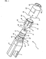
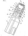
- Fig. 1 One example of preferable embodiments of the assembly of adjusting the pricking depth according to the present invention is shown in Fig. 1 in an exploded perspective view and in shown In Fig. 2 in a partially cut-away and assembled perspective view.
- the assembly 1 is composed of the cap element 3, the adjusting element 5 and the cover element 7.
- the adjusting element 5 is put onto the end portion 11 of the cap element 3 and then rotated or pushed into as it is, and then the cover element 7 is pushed onto and fitted to the adjusting element 5, whereby the present assembly 1 according to the present invention is completed.
- the assembly according to the present invention is generally in the form of a cylinder and preferably a cylinder partially containing tapered portions.
- the assembly has been formed by assembling those elements coaxially.
- the cap element 3 its one end portion 9 is so constructed that an injector (not shown) is fitted into the end portion for engagement, and the adjusting element 5 is mounted onto other end portion 11.
- the other end portion 11 comprises a cylindrical portion having the stop means 13, the cap element thread portion 17, the step portions 37 and the recess portions 41.
- An end surface of the end portion 11 functions as the stop means 13 and has the opening 15 in its center portion.
- an engagement means is provided onto the Inside of the end portion 9 of the cap element 3, and the injector has an engagement means which is mated with the engagement means of the cap element.
- the engagement of the cap element 3 with the injector may achieved in any suitable manner.
- the cap element 3 is conveniently mounted onto or disengaged from the Injector with snap-fitting or screw mechanism fastening.
- the embodiment shown in the drawings corresponds to the snap-fitting engagement, and a protruding portion (which cannot be seen) of the cap element 3 is such that it is engaged with a recess portion of the injector.
- a lancet After a lancet has been ejected by the injector, it rapidly moves within the inside of the cap element 3 along a direction of the arrow A and a pricking element of the lancet passes through the opening 15 to expose out of the cap element 3. Thus, a tip of the pricking element passes through the opening 33 of the cover element 7 and is exposed outside of the cover element 7.
- an end portion of the lancet abuts against the inside of the end surface 13 so that kinetic energy that the lancet has is absorbed, immediately after which the lancet goes back toward the injector (i.e. a direction opposite to the arrow A) by an elastic member of the injector which tends to recover its original free state. That is, the lancet is retracted into the inside of the cap element 3 through the opening 15.
- the end portion 11 includes the thread portion 17, which may be such that ridge and groove portions are flat as shown or have U or V-shaped cross sections.
- the number of turns of the thread is not specifically limited, but a lead of the thread (a proceeding length of the thread with one turn) is selected so that preferably about half turn (or rotation), and more preferably about 3/8 - 4/9 turn achieves a whole variable pricking depth range (i.e. from the deepest pricking depth to the shallowest pricking depth). By such selection, a desired pricking depth is available without unnecessarily large number of rotations.
- the cap element 3 has the peripheral step portion 37 which is adjacent to the thread portion 17, and the step portion includes at least one recess portion (for example groove) 39 for clicking.
- the recess portion has a shape and a size which allow the protruding portion 57 provided onto the adjusting element 5 (see Fig. 2) to fit into the recess portion 39 so as to achieve clicking.
- the adjusting element 5 and the cap element 3 are in an engagement state with clicking at a predetermined rotation position so that a user easily recognizes that a desired pricking depth has been set.
- the cap element 3 comprises at least two peripheral recess portions (concave portions) 41 adjacent to the step portions 37 into which recess portions the protruding portions 51 provided on the end portions 23 of the adjusting element 5 are placed respectively, whereby the adjusting element 5 is engaged with but axially rotatable around the cap element 3.
- Each of those plural recess portions 41 has a predetermined peripheral length and a predetermined axial length (or width), and they are separated by the stop portion 43 from each other. Therefore, the recess portions 41 and the stop portions 43 are arranged alternatively around the cap element 3 symmetrically and regularly.
- the protruding portion 51 placed into the recess portion 41 can move along the same direction as that of the thread portion, but the movement within the portion 41 is limited along the peripheral direction since the protruding portion 51 abuts against the stop portion 43 at an end of the recess portion 41.
- the adjusting element 5 moves axially relative to the cap element 3 by the rotation thereof, and the width of the recess portion 41 is such that it does not prevent the axial relative movement. That is, the protruding portion 51 has to be moved axially in the recess portion 41 by a distance by which the adjusting element 5 axially moves relative to the cap element 3.
- a peripheral length of the recess portion 41 is such that the adjusting element 5 can be rotated as desired. That is, the length is one which is required for the thread portion 17 to follow so as to achieve a desired variable pricking depth range. Also, an axial length of the recess portion 41 is one which allows the desired rotation.
- the adjusting element 5 is generally in the form of a cylinder as a whole, and so constructed that it receives the end portion 11 of the cap element 3 except the vicinity of the end surface 13 in the inside thereof.
- the adjusting element 5 comprises a plurality of the slits 19 which extend longitudinally from an end of the element 5 which is near the injector when the assembly is assembled. These slits divide a cylindrical side surface of the adjusting element into a plurality of the peripheral flap portions 21, which are connected together at the other end through the annular ring portion 45.
- the flap portions 21 can be opened outward elastically at the annular ring portion 45 as a base.
- At least one of the peripheral flap portion 21 comprises the tab portion 23 which has the protruding portion 51 on its inside end.
- the protruding portion 51 falls into the recess portion 41 of the cap element as described above, whereby the peripheral screw-like rotation of the protruding portion 51 of the adjusting element 5 is allowed within the recess portion 41 while undue removal of the adjusting element 5 from the cap element 3 is prevented.
- At least one of the peripheral flap portion 21 of the adjusting element 5 comprises another protruding portion 53 as a thread portion on its Inside.
- the thread portion 53 is so constructed that it is engaged with the thread portion 17 of the cap element 3 through the screw engagement mechanism, and thus the protruding portio 53 is present as a thread which is placed into the thread groove 47 of the thread portion 17.
- a length along a spiral direction (i.e. the direction of the arrow B in Fig. 2) of the thread portion 53 is not specifically limited, and it may be very short.
- a length along a screw proceeding direction (i.e. the direction of the arrow C in Fig. 2) of the thread portion 53 is preferably such that the thread portion 53 is substantially tightly fitted into the thread groove 47 to achieve the screw like rotation, whereby rattling is prevented between the cap element 3 and the adjusting element 5, which improves adjustment accuracy of the pricking depth.
- the engagement of the thread groove 47 with the thread portion 53 makes the adjusting element 5 possible to go forward or backward relative to the cap element 3 along axis of these element when the adjusting element 5 is rotated relative to the cap element 3.
- the above rotation is limited by the stop portion 43 of the cap element 3. That is, the peripheral movement of the protruding portion 51 within the recess portion 41 is stopped by abutment of the protruding element 51 against the stop portion 43.
- the protruding portion 51 upon being stopped, the protruding portion 51 abuts against the wall portion 61 or 63 at an edge on a lancet ejection side or an opposite side thereto of the recess portion 41.
- the wall portions of the recess portion 41 function as stop means (one of the wall portions 63 simultaneously forms the stop portion 37).
- the protruding portion 51 moves along a combined direction of the directions of the arrows B and C (or opposite directions thereto), namely the direction of the thread upon the rotation of the adjusting element 5.
- the cap element 3 comprises the recess portions 39 for clicking on the step portion 37 in the shown embodiment.
- the protruding portion 57 for clicking provided on the Inside of the tab portion 23 of the adjusting element is fitted into the recess portions 39.
- a clicking situation upon fitting as described above when the cover element 7 is incorporated onto the adjusting element 5, there is a small space between the tab portion 23 and an inner wall of the cover element 7 as seen from Fig. 2.
- the adjusting element 5 moves between the cap element 3 and the cover element 7 while the tab portion 23 is opened outward a little.
- Such clicking and the movement as described are possible since the element constituting material can be deformed elastically.
- the recess portions 39 and the protruding portion 57 may be eliminated.
- the adjusting element 5 has the recess portion 29 on its outside, which is so constructed that the protruding portion 65 (schematically shown in the broken line) provided on the inside of the cover element 7 is engaged with the recess portion 29.
- this engagement is easily formed by pushing the cover element 7 along the direction opposite to the arrow A onto the adjusting element 5, and easily disengaged by pulling the cover element 7 along the direction of the arrow A in a completed assembly.
- the engagement and the disengagement are achieved by the use of interference fit.
- the recess portion 29 is preferably fully opened at the end surface of the adjusting element 5. The engagement state allows the adjusting element 5 and the cover element 7 to peripherally rotate together while the formation or the release of the engagement is possible by applying a force along the arrow A direction or the opposite direction thereto.
- the cover element 7 comprises the opening 31 into which the adjusting element Is inserted and the end surface 35 having the opening 33 against which the object to be pricked is placed. As shown in the drawings, the end surface 35 may be retracted a little from the end of the cover element 7.
- the adjusting element 5 When assembled as shown in Fig. 2, the adjusting element 5 is rotated upon the rotation of the cover element 7 around its axis, whereby the adjusting element 5 and the cover element 7 which is integral therewith moves forward or backward relative to the cap element 3 by means of the screw mechanism. That is, a length between the end surface 13 of the cap element 3 and the end surface 35 of the cover element 7 is changed, which enables the pricking depth of the pricking element to be adjusted.
- the pricking depth corresponds to a protruding length of the pricking element from the end surface 35; since the movement of the lancet is stopped by the end surface 13 after the ejection of the lancet, when the length is changed between the end surfaces 13 and 35, the protruding length of the pricking element from the end surface (and thus the pricking depth) is changed even though the protruding length from the end surface 13 of the pricking element is constant.
- the cover element 7 and the adjusting element 5 moves together relative to the cap element along the lancet ejection direction, whereby the distance between the end surfaces 13 and 35 is changed.
- the lancet is stopped by the stop means 13, and thus the protruding length of the pricking element from the end surface 35 is changeable.
- the adjusting element 5 comprises at least one protruding portion 25 on its outside surface.
- the protruding portion 25 may be engaged with the recess portion 55 provided on the inside of the cover element 7 by means of snap-fitting.
- the numbers of the protruding portions 25 and the recess portions 55 are not specifically limited provided that sufficient engagement is achieved between the cover element 7 and the peripheral flap portions 21 of the adjusting element 5. This engagement prevents undue outward opening of the flap portions 21 of the adjusting element 5.
- the adjusting element 5 is put onto the end portion 11 having the end surface 13, and then the adjusting element 5 and the cap element 3 are then relatively rotated along the screw fastening directions so as to place the tab portions 23 on the step portions 37.
- the tab portions 23 abut stop portions 43 so that the rotation is stopped.
- the cover element 7 is incorporated onto the adjusting element 5 which has been incorporated onto the cap element 3.
- This incorporation may be carried out by moving the cover element 7 along the direction opposite to the arrow A so as to put the cover element 7 on the adjusting element 5 and engage the protruding portion 65 provided on the inside of the cover element 7 with the recess portion 29 of the adjusting element 5.
- Such movement fits the protruding portions 25 of the adjusting element into the recess portions 55 of the cover element, whereby the ends of the peripheral flap portions 21 and the tabs 23 push the step portions 37 properly.
- the term "properly” means that the cover element 7 and the adjusting element 5 incorporated together can be rotated relative to the cap element 3 with clicking at a predetermined interval by means of a force applied with fingers.
- the present assembly is based on the screw mechanism as described above.
- the assembly in a position of the maximum pricking depth is shown in Fig. 3 and the assembly in a position of the minimum pricking depth is shown in Fig. 4, each of which is shown in a schematic cross sectional view.
- the end surface 13 of the cap element 3 is in contact with the end surface 35 of the cover element 7, and when the depth is the minimum, there is a cavity 71 between these end surfaces.
- the protruding portion 51 provided on the tab portion of the adjusting element 5 has moved within the recess portion 41 along the lancet ejection direction. In the embodiment shown in Fig. 3, the protruding portion 51 abuts against the wall portion 61.
- Figs. 3 and 4 show the lancet 75 having the protruding pricking element 73 at a moment when the end 77 of the lancet 75 has just abutted against the end surface 13 as the stop means.
- the protruding length of the pricking element from the end surface 35 is substantially equal to the pricking depth.
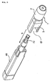
- the rear end 81 of the cap element was provided with a cross section and an engagement means which allow the attachment of the cap element to the injector body 83 of "PENLET II" injector (thus, the same cross section and the same engagement means as those of the cap element of "PENLET II” injector ), whereby the present assembly 1 including the cap element 3 was attached to the injector 83 so as to give it the pricking depth (multistage) adjusting function.
- Fig. 5 the injector 83 and the present assembly 1 are shown separately, but the attachment of the assembly to the injector is achieved by pushing, along the arrow D direction, the present assembly onto the injector 83 to which the lancet 75 has been attached.
- Each element of the present assembly were formed using an injection molders and metal molds.
- the thread portion, the stop portions and the recess portions and so on were formed in the end portions of the cap element, and only this end portion was fabricated into a split mold.
- As the molder 40-ton injection molder (from Nissei Plastic Industrial Co., Ltd.) was used, and the molded elements were obtained.
- the cap element had the following sizes: Total length 52.9 mm Width 14.6 mm Height 14.6 mm Thickness of end surface as stop means 0.4 mm
- the pitch of the thread was 4 mm
- a rotation angle range of the adjusting ring was 90 degrees
- a difference between positions of the maximum pricking depth and the minimum pricking depth (thus, the pricking depth variable range) was 1.0 mm, which was divided into 5 stages by provisions of five recess portions for clicking.
- an adjustable pricking depth by a single stage was 0.25 mm each.
- a polyacetal resin (Tenac #4520 commercially available from Asahi Chemical Industry Co., Ltd.) was used as a material for the adjusting element considering elastic properties, resistance to fatigue from flexing and sliding friction resistance with respect to the ABS resin.
- the element was such that it had the protruding portions which fall into and connect to the recess portions of the cap element, the protruding portions which corresponds to the thread portions of the cap element, the four slits to divide the cylindrical wall into the flap portions, the recess portion which is engaged with the cover element and so on.
- the metal mold was fabricated for a single piece. 20-Ton injection molder (Nissei Plastic Industrial Co., Ltd.) was used, and the molded elements having the following sizes were obtained: Outer diameter 13.0 mm Inner diameter 10.04 mm Length 14.2 mm
- a PBT resin (PBT #1401X07 commercially available from Toray Industries, Inc.) was used as a material for the cover element considering resistance against body fluid contamination, texture upon handling, stiffness required to press the adjusting element against the cap element and so on.
- Protruding portion was provided on the inside of the cover element.
- the metal mold was fabricated for a single piece. 40-Ton injection molder (Nissel Plastic Industrial Co., Ltd.) was used, and the molded elements having the following sizes were obtained: Length 22.0 mm Outer diameter 14.8 mm Inner diameter 13.3 mm Thickness of end surface at front end 0.4 mm
- the adjusting element was pushed straight onto the cap element while both axes were aligned.
- the flap portions opened outward because of the elasticity of the adjusting ring (or element), in particular the elastic behavior of the flap portions, so that incorporation was easy even with straight pushing without rotation of the adjusting element. That is, the protruding portions provided on the inside of the tab portions were placed Into the recess portions of the cap element.
- the unitary cover element + adjusting element as the pricking depth adjusting mechanism was rotated to the first adjusting stage.
- the adjusting mechanism was stopped at a position of the first stage with a clicking sound.
- the cover element When measured using a slide gauge, the cover element advanced 0.25 mm relative to the cap element. Then, rotating through the second stage to the fifth stage, and the rotation was surely stopped at every stage with the clicking sound and the advance length of 0.25 mm each. When reversely rotated, receding by every 0.25 mm was ensured.
- the cover element did not slip on the adjusting element.
- a lancet was attached to the injector, and then the present assembly was attached to the injector after setting to a predetermined pricking depth. Then, the lancet was ejected twenty times successively, and the adjusting mechanism was not changed from the set position at all.
- the adjusting mechanism was set at from the first stage to the fifth stage, and then from the fifth stage to the first stage successively fifty times, after which whether or not the adjusting mechanism stopped at every stage correctly was checked.
- the mechanism surely stopped at the same positions as in the original assembly before testing.
- the present assembly is suitable for the mass production in which no problem occurs in its function, and the assembly has stable product performance and quality.
Claims (10)
- Anordnung (1), die an einem Injektor angebracht ist, der eine Lanzette auswirft, die ein Pikierelement (73) aufweist, das davon vorsteht, und der die Pikiertiefe des Pikierelements (73) in ein zu pikierendes Objekt justiert, umfassend:dadurch gekennzeichnet, dassein Kappenelement (3), das an dem Injektor anbringbar ist; undein Abdeckelement (7), durch das das Pikierelement (73), das zur Außenseite freigegeben ist, sich erstreckt, und das eine Öffnung (33) aufweist, gegen die das zu pikierende Objekt platziert wird,
das Kappenelement (3) eine Anschlageinrichtung (13) aufweist, die die Bewegung der Lanzette, während das Pikierelement (73) zur Außenseite des Kappenelements freigegeben ist, nachdem die Lanzette ausgeworfen ist, durch Berührung eines Endes der Lanzette, aus der das Pikierelement vorsteht, gegen die Anschlageinrichtung (13) stoppt,
die Anordnung ein Justierelement umfasst, das mit dem Kappenelement (3) und dem Abdeckelement (7) zwischen diesen Elementen in Eingriff ist, und
ein Abstand zwischen der Anschlageinrichtung (13) und der Öffnung (33) entlang der Richtung des Lanzettenauswurfs durch Drehung des Justierelements (5) mit der Richtung des Lanzettenauswurfs als Drehpunkt veränderbar ist. - Anordnung (1) nach Anspruch 1, wobei das Abdeckelement (7) und das Justierelement (5) zusammen um die Richtung des Lanzettenauswurfs als Achse rotieren können und das Justierelement (5) und das Kappenelement (3) so konstruiert sind, dass sie ein Eingriffsverhältnis durch einen Schraubenmechanismus (17, 47, 53) eingehen.
- Anordnung (1) nach Anspruch 1 oder 2, wobei das Kappenelement (3) einen Kappenelement-Gewindebereich (17) auf der Außenseite eines Endbereichs des Kappenelements (3) umfasst, das Abdeckelement (7) einen vorspringenden Bereich (65) auf seiner Innenseite umfasst, und das Justierelement (5) einen Justierelement-Gewindebereich auf seiner Innenseite, der mit dem Kappenelement-Gewindebereich (17) in Eingriff ist, und einen ausgesparten Bereich (29) auf seiner Außenseite umfasst, der mit dem vorspringenden Bereich (65) des Abdeckelements im Eingriff ist.
- Anordnung (1) nach einem der Ansprüche 1 bis 3, wobei das Justierelement (5) mehrere Schlitze (19) aufweist, die sich von seinem an dem Injektor zu befestigenden Ende so erstrecken, dass das Justierelement (5) in Laschenbereiche (21) geteilt ist, die miteinander am anderen Ende des Justierelements (5) verbunden sind, und die Laschenbereiche (21) so gestaltet sind, dass sie elastisch zu öffnen sind, während sie am anderen Ende als Basis gestützt werden.
- Anordnung (1) nach einem der Ansprüche 1 bis 4, wobei das Kappenelement (3) einen Anschlagbereich (13) hat, gegen den ein vorspringender Bereich (25) des Justierelements (5) stößt, so dass die Rotation des Justierelements begrenzt ist.
- Anordnung (1) nach einem der Ansprüche 1 bis 5, wobei das Abdeckelement die elastische Deformation des Justierelements begrenzt.
- Blutsammeleinrichtung, die sich aus der Anordnung (1) nach einem der Ansprüche 1 bis 6 und einem Injektor zusammensetzt.
- Kappenelement (3) zur Bildung der Anordnung (1) nach einem der Ansprüche 1-6.
- Justierelement (5) zur Bildung der Anordnung (1) nach einem der Ansprüche 1-6.
- Abdeckelement (7) zur Bildung der Anordnung (1) nach einem der Ansprüche 1-6.
Applications Claiming Priority (4)
| Application Number | Priority Date | Filing Date | Title |
|---|---|---|---|
| JP192987/95 | 1995-07-28 | ||
| JP19298795 | 1995-07-28 | ||
| JP19298795 | 1995-07-28 | ||
| PCT/JP1996/002085 WO1997004707A1 (en) | 1995-07-28 | 1996-07-25 | Assembly for adjusting piercing depth of lancet |
Publications (3)
| Publication Number | Publication Date |
|---|---|
| EP0783868A1 EP0783868A1 (de) | 1997-07-16 |
| EP0783868A4 EP0783868A4 (de) | 1997-09-24 |
| EP0783868B1 true EP0783868B1 (de) | 2003-04-09 |
Family
ID=16300353
Family Applications (1)
| Application Number | Title | Priority Date | Filing Date |
|---|---|---|---|
| EP96925082A Expired - Lifetime EP0783868B1 (de) | 1995-07-28 | 1996-07-25 | Vorrichtung zum einstellen der eindringtiefe einer lanzette |
Country Status (6)
| Country | Link |
|---|---|
| US (1) | US5730753A (de) |
| EP (1) | EP0783868B1 (de) |
| JP (1) | JP3638958B2 (de) |
| CA (1) | CA2201317C (de) |
| DE (1) | DE69627288T2 (de) |
| WO (1) | WO1997004707A1 (de) |
Cited By (2)
| Publication number | Priority date | Publication date | Assignee | Title |
|---|---|---|---|---|
| US8905971B2 (en) | 2005-12-02 | 2014-12-09 | Owen Mumford, Ltd. | Injection method and apparatus |
| US8998855B2 (en) | 2008-11-17 | 2015-04-07 | Owen Mumford, Ltd. | Syringe and needle cover remover |
Families Citing this family (217)
| Publication number | Priority date | Publication date | Assignee | Title |
|---|---|---|---|---|
| US6395227B1 (en) | 1989-08-28 | 2002-05-28 | Lifescan, Inc. | Test strip for measuring analyte concentration over a broad range of sample volume |
| CA2551185C (en) * | 1994-03-28 | 2007-10-30 | Sdgi Holdings, Inc. | Apparatus and method for anterior spinal stabilization |
| US20020010406A1 (en) * | 1996-05-17 | 2002-01-24 | Douglas Joel S. | Methods and apparatus for expressing body fluid from an incision |
| US6015392A (en) * | 1996-05-17 | 2000-01-18 | Mercury Diagnostics, Inc. | Apparatus for sampling body fluid |
| US5951493A (en) * | 1997-05-16 | 1999-09-14 | Mercury Diagnostics, Inc. | Methods and apparatus for expressing body fluid from an incision |
| EP1579814A3 (de) * | 1996-05-17 | 2006-06-14 | Roche Diagnostics Operations, Inc. | Verfahren und Vorrichtung zur Probenahme und Analyse von Körperflüssigkeit |
| US7235056B2 (en) | 1996-05-17 | 2007-06-26 | Amira Medical | Body fluid sampling device and methods of use |
| ES2121564B1 (es) | 1996-05-17 | 2001-02-01 | Mercury Diagnostics Inc | Metodos y aparatos para extraer fluido corporal desde una incision. |
| US7828749B2 (en) * | 1996-05-17 | 2010-11-09 | Roche Diagnostics Operations, Inc. | Blood and interstitial fluid sampling device |
| US5916230A (en) * | 1997-06-16 | 1999-06-29 | Bayer Corporation | Blood sampling device with adjustable end cap |
| US5868772A (en) * | 1997-07-31 | 1999-02-09 | Bayer Corporation | Blood sampling device with anti-twist lancet holder |
| US5964718A (en) * | 1997-11-21 | 1999-10-12 | Mercury Diagnostics, Inc. | Body fluid sampling device |
| US6706000B2 (en) | 1997-11-21 | 2004-03-16 | Amira Medical | Methods and apparatus for expressing body fluid from an incision |
| US6036924A (en) | 1997-12-04 | 2000-03-14 | Hewlett-Packard Company | Cassette of lancet cartridges for sampling blood |
| WO1999032883A2 (en) | 1997-12-19 | 1999-07-01 | Amira Medical | Embossed test strip system |
| US6949111B2 (en) | 1998-02-13 | 2005-09-27 | Steven Schraga | Lancet device |
| US6391005B1 (en) | 1998-03-30 | 2002-05-21 | Agilent Technologies, Inc. | Apparatus and method for penetration with shaft having a sensor for sensing penetration depth |
| US6346114B1 (en) * | 1998-06-11 | 2002-02-12 | Stat Medical Devices, Inc. | Adjustable length member such as a cap of a lancet device for adjusting penetration depth |
| US7175641B1 (en) | 1998-06-11 | 2007-02-13 | Stat Medical Devices, Inc. | Lancet having adjustable penetration depth |
| US6022366A (en) * | 1998-06-11 | 2000-02-08 | Stat Medical Devices Inc. | Lancet having adjustable penetration depth |
| US6558402B1 (en) * | 1999-08-03 | 2003-05-06 | Becton, Dickinson And Company | Lancer |
| US6283982B1 (en) * | 1999-10-19 | 2001-09-04 | Facet Technologies, Inc. | Lancing device and method of sample collection |
| CA2287757A1 (en) | 1999-10-29 | 2001-04-29 | Medical Plastic Devices M.P.D. Inc. | Disposable lancet |
| US20050070945A1 (en) * | 1999-11-02 | 2005-03-31 | Steven Schraga | Single use lancet assembly |
| US6258112B1 (en) | 1999-11-02 | 2001-07-10 | Steven Schraga | Single use lancet assembly |
| US8814896B2 (en) | 1999-11-02 | 2014-08-26 | Stat Medical Devices, Inc. | Single use lancet assembly |
| US20060091006A1 (en) * | 1999-11-04 | 2006-05-04 | Yi Wang | Analyte sensor with insertion monitor, and methods |
| US6616819B1 (en) * | 1999-11-04 | 2003-09-09 | Therasense, Inc. | Small volume in vitro analyte sensor and methods |
| US6322575B1 (en) | 2000-01-05 | 2001-11-27 | Steven Schraga | Lancet depth adjustment assembly |
| US6530937B1 (en) | 2000-01-28 | 2003-03-11 | Stat Medical Devices, Inc. | Adjustable tip for a lancet device and method |
| US6706159B2 (en) * | 2000-03-02 | 2004-03-16 | Diabetes Diagnostics | Combined lancet and electrochemical analyte-testing apparatus |
| PL191428B1 (pl) * | 2000-04-06 | 2006-05-31 | Htl Strefa Sp Z Oo | Zespół regulacji głębokości nakłucia w przyrządzie do nakłuwania |
| US7344546B2 (en) * | 2000-04-05 | 2008-03-18 | Pathway Medical Technologies | Intralumenal material removal using a cutting device for differential cutting |
| DE10026172A1 (de) | 2000-05-26 | 2001-11-29 | Roche Diagnostics Gmbh | System zur Entnahme von Körperflüssigkeit |
| PL195673B1 (pl) * | 2000-06-09 | 2007-10-31 | Diabetes Diagnostics Inc | Nasadka do urządzenia nacinającego |
| TW495353B (en) | 2000-09-01 | 2002-07-21 | Bayer Ag | Adjustable endcap for lancing device |
| US8641644B2 (en) | 2000-11-21 | 2014-02-04 | Sanofi-Aventis Deutschland Gmbh | Blood testing apparatus having a rotatable cartridge with multiple lancing elements and testing means |
| EP1358844B1 (de) * | 2001-01-12 | 2010-09-01 | ARKRAY, Inc. | Punktiervorrichtung |
| US6530892B1 (en) * | 2001-03-07 | 2003-03-11 | Helen V. Kelly | Automatic skin puncturing system |
| EP1393678A4 (de) * | 2001-06-07 | 2007-05-09 | Arkray Inc | Ausstossvorrichtung |
| US20020188223A1 (en) * | 2001-06-08 | 2002-12-12 | Edward Perez | Devices and methods for the expression of bodily fluids from an incision |
| US7749174B2 (en) | 2001-06-12 | 2010-07-06 | Pelikan Technologies, Inc. | Method and apparatus for lancet launching device intergrated onto a blood-sampling cartridge |
| US9226699B2 (en) | 2002-04-19 | 2016-01-05 | Sanofi-Aventis Deutschland Gmbh | Body fluid sampling module with a continuous compression tissue interface surface |
| US7033371B2 (en) | 2001-06-12 | 2006-04-25 | Pelikan Technologies, Inc. | Electric lancet actuator |
| US8337419B2 (en) * | 2002-04-19 | 2012-12-25 | Sanofi-Aventis Deutschland Gmbh | Tissue penetration device |
| US7041068B2 (en) | 2001-06-12 | 2006-05-09 | Pelikan Technologies, Inc. | Sampling module device and method |
| ATE450210T1 (de) | 2001-06-12 | 2009-12-15 | Pelikan Technologies Inc | Selbstoptimierende lanzettenvorrichtung mit adaptationsmittel für zeitliche schwankungen von hauteigenschaften |
| US9795747B2 (en) | 2010-06-02 | 2017-10-24 | Sanofi-Aventis Deutschland Gmbh | Methods and apparatus for lancet actuation |
| US7981056B2 (en) | 2002-04-19 | 2011-07-19 | Pelikan Technologies, Inc. | Methods and apparatus for lancet actuation |
| EP1404232B1 (de) | 2001-06-12 | 2009-12-02 | Pelikan Technologies Inc. | Gerät und verfahren zur entnahme von blutproben |
| US7344507B2 (en) | 2002-04-19 | 2008-03-18 | Pelikan Technologies, Inc. | Method and apparatus for lancet actuation |
| US9427532B2 (en) | 2001-06-12 | 2016-08-30 | Sanofi-Aventis Deutschland Gmbh | Tissue penetration device |
| ATE497731T1 (de) | 2001-06-12 | 2011-02-15 | Pelikan Technologies Inc | Gerät zur erhöhung der erfolgsrate im hinblick auf die durch einen fingerstich erhaltene blutausbeute |
| CA2450711C (en) * | 2001-06-13 | 2010-11-02 | Steven Schraga | Single use lancet device |
| CN1267056C (zh) * | 2001-07-11 | 2006-08-02 | 爱科来株式会社 | 穿刺装置 |
| US8048097B2 (en) * | 2001-08-14 | 2011-11-01 | Steven Schraga | Single use lancet assembly |
| US6918918B1 (en) | 2001-08-14 | 2005-07-19 | Steven Schraga | Single use lancet assembly |
| EP1423049A2 (de) * | 2001-08-29 | 2004-06-02 | Roche Diagnostics GmbH | Drainageverfahren und -strukturen zur verwendung bei der probenentnahme von körperflüssigkeiten |
| US6645219B2 (en) * | 2001-09-07 | 2003-11-11 | Amira Medical | Rotatable penetration depth adjusting arrangement |
| AU2002324999A1 (en) * | 2001-09-13 | 2003-03-24 | Facet Technologies, Llc | Adjustable depth lancing device |
| EP1432353A1 (de) | 2001-09-26 | 2004-06-30 | Hoffman-La Roche AG | Verfahren und vorrichtung zur entnahme von körperflüssigkeiten |
| US20030100913A1 (en) * | 2001-10-09 | 2003-05-29 | Guoping Shi | Depth adjustable cap of lancing device |
| US20040098010A1 (en) * | 2001-10-22 | 2004-05-20 | Glenn Davison | Confuser crown skin pricker |
| WO2003037185A1 (fr) * | 2001-10-31 | 2003-05-08 | Arkray, Inc. | Dispositif a aiguille |
| CA2468983C (en) * | 2001-12-07 | 2013-12-17 | Micronix, Inc. | Consolidated body fluid testing device and method |
| US7357808B2 (en) * | 2002-01-31 | 2008-04-15 | Facet Technologies, Llc | Single use device for blood microsampling |
| US7004928B2 (en) | 2002-02-08 | 2006-02-28 | Rosedale Medical, Inc. | Autonomous, ambulatory analyte monitor or drug delivery device |
| GB2413964B (en) * | 2002-03-06 | 2006-02-08 | Htl Strefa Spolka Z O O | A device for puncturing patient's skin |
| US7229458B2 (en) | 2002-04-19 | 2007-06-12 | Pelikan Technologies, Inc. | Method and apparatus for penetrating tissue |
| US7371247B2 (en) | 2002-04-19 | 2008-05-13 | Pelikan Technologies, Inc | Method and apparatus for penetrating tissue |
| US7909778B2 (en) | 2002-04-19 | 2011-03-22 | Pelikan Technologies, Inc. | Method and apparatus for penetrating tissue |
| US7491178B2 (en) | 2002-04-19 | 2009-02-17 | Pelikan Technologies, Inc. | Method and apparatus for penetrating tissue |
| US8267870B2 (en) | 2002-04-19 | 2012-09-18 | Sanofi-Aventis Deutschland Gmbh | Method and apparatus for body fluid sampling with hybrid actuation |
| US7892185B2 (en) | 2002-04-19 | 2011-02-22 | Pelikan Technologies, Inc. | Method and apparatus for body fluid sampling and analyte sensing |
| US7374544B2 (en) * | 2002-04-19 | 2008-05-20 | Pelikan Technologies, Inc. | Method and apparatus for penetrating tissue |
| US9795334B2 (en) | 2002-04-19 | 2017-10-24 | Sanofi-Aventis Deutschland Gmbh | Method and apparatus for penetrating tissue |
| US7892183B2 (en) | 2002-04-19 | 2011-02-22 | Pelikan Technologies, Inc. | Method and apparatus for body fluid sampling and analyte sensing |
| US9314194B2 (en) | 2002-04-19 | 2016-04-19 | Sanofi-Aventis Deutschland Gmbh | Tissue penetration device |
| US7297122B2 (en) | 2002-04-19 | 2007-11-20 | Pelikan Technologies, Inc. | Method and apparatus for penetrating tissue |
| US8702624B2 (en) | 2006-09-29 | 2014-04-22 | Sanofi-Aventis Deutschland Gmbh | Analyte measurement device with a single shot actuator |
| US7291117B2 (en) | 2002-04-19 | 2007-11-06 | Pelikan Technologies, Inc. | Method and apparatus for penetrating tissue |
| US7674232B2 (en) | 2002-04-19 | 2010-03-09 | Pelikan Technologies, Inc. | Method and apparatus for penetrating tissue |
| US7717863B2 (en) | 2002-04-19 | 2010-05-18 | Pelikan Technologies, Inc. | Method and apparatus for penetrating tissue |
| US8221334B2 (en) | 2002-04-19 | 2012-07-17 | Sanofi-Aventis Deutschland Gmbh | Method and apparatus for penetrating tissue |
| US7331931B2 (en) * | 2002-04-19 | 2008-02-19 | Pelikan Technologies, Inc. | Method and apparatus for penetrating tissue |
| US7976476B2 (en) | 2002-04-19 | 2011-07-12 | Pelikan Technologies, Inc. | Device and method for variable speed lancet |
| US7232451B2 (en) | 2002-04-19 | 2007-06-19 | Pelikan Technologies, Inc. | Method and apparatus for penetrating tissue |
| US8579831B2 (en) | 2002-04-19 | 2013-11-12 | Sanofi-Aventis Deutschland Gmbh | Method and apparatus for penetrating tissue |
| US7198606B2 (en) | 2002-04-19 | 2007-04-03 | Pelikan Technologies, Inc. | Method and apparatus for a multi-use body fluid sampling device with analyte sensing |
| US7901362B2 (en) | 2002-04-19 | 2011-03-08 | Pelikan Technologies, Inc. | Method and apparatus for penetrating tissue |
| US8784335B2 (en) | 2002-04-19 | 2014-07-22 | Sanofi-Aventis Deutschland Gmbh | Body fluid sampling device with a capacitive sensor |
| US8360992B2 (en) | 2002-04-19 | 2013-01-29 | Sanofi-Aventis Deutschland Gmbh | Method and apparatus for penetrating tissue |
| US9248267B2 (en) | 2002-04-19 | 2016-02-02 | Sanofi-Aventis Deustchland Gmbh | Tissue penetration device |
| US7648468B2 (en) | 2002-04-19 | 2010-01-19 | Pelikon Technologies, Inc. | Method and apparatus for penetrating tissue |
| US7547287B2 (en) | 2002-04-19 | 2009-06-16 | Pelikan Technologies, Inc. | Method and apparatus for penetrating tissue |
| US20040039407A1 (en) * | 2002-04-29 | 2004-02-26 | Steven Schraga | Lancet device |
| US8715309B2 (en) | 2002-04-29 | 2014-05-06 | Steven Schraga | Lancet device |
| WO2003101297A2 (en) * | 2002-05-31 | 2003-12-11 | Facet Technologies, Llc | Precisely guided lancet |
| US7572237B2 (en) * | 2002-11-06 | 2009-08-11 | Abbott Diabetes Care Inc. | Automatic biological analyte testing meter with integrated lancing device and methods of use |
| CN100360086C (zh) * | 2002-11-15 | 2008-01-09 | 爱科来株式会社 | 刺血针以及穿刺装置 |
| US20060184189A1 (en) * | 2002-11-15 | 2006-08-17 | Lorin Olson | Cap for a dermal tissue lancing device |
| US20040127818A1 (en) | 2002-12-27 | 2004-07-01 | Roe Steven N. | Precision depth control lancing tip |
| US8574895B2 (en) | 2002-12-30 | 2013-11-05 | Sanofi-Aventis Deutschland Gmbh | Method and apparatus using optical techniques to measure analyte levels |
| EP1589873B1 (de) * | 2003-01-29 | 2011-12-21 | Roche Diagnostics GmbH | Integrierter lanzetten-teststreifen |
| AU2004200523A1 (en) * | 2003-02-19 | 2004-09-09 | Bayer Healthcare, Llc | Endcap for Lancing Device and Method of Use |
| US7288102B2 (en) * | 2003-03-20 | 2007-10-30 | Facet Technologies, Llc | Lancing device with decoupled lancet |
| US7494498B2 (en) * | 2003-03-24 | 2009-02-24 | Facet Technologies, Llc | Lancing device with floating lancet |
| US7052652B2 (en) | 2003-03-24 | 2006-05-30 | Rosedale Medical, Inc. | Analyte concentration detection devices and methods |
| KR200315777Y1 (ko) * | 2003-03-24 | 2003-06-11 | 김용필 | 일회용 사혈침기구 |
| US20040254599A1 (en) * | 2003-03-25 | 2004-12-16 | Lipoma Michael V. | Method and apparatus for pre-lancing stimulation of puncture site |
| US20080149524A1 (en) * | 2003-03-27 | 2008-06-26 | Rademaker William B | Food containers including dental cleaning devices and other personal care items |
| US7988957B2 (en) * | 2003-04-25 | 2011-08-02 | Genesis Healthcare Corp. | Gene introduction efficiency enhancer |
| US7621931B2 (en) * | 2003-05-20 | 2009-11-24 | Stat Medical Devices, Inc. | Adjustable lancet device and method |
| JP4761701B2 (ja) * | 2003-05-21 | 2011-08-31 | アークレイ株式会社 | 穿刺深さを調整可能な穿刺装置 |
| US8262614B2 (en) | 2003-05-30 | 2012-09-11 | Pelikan Technologies, Inc. | Method and apparatus for fluid injection |
| ES2490740T3 (es) | 2003-06-06 | 2014-09-04 | Sanofi-Aventis Deutschland Gmbh | Aparato para toma de muestras de fluido sanguíneo y detección de analitos |
| WO2006001797A1 (en) | 2004-06-14 | 2006-01-05 | Pelikan Technologies, Inc. | Low pain penetrating |
| US7905898B2 (en) * | 2003-08-15 | 2011-03-15 | Stat Medical Devices, Inc. | Adjustable lancet device and method |
| US7105006B2 (en) * | 2003-08-15 | 2006-09-12 | Stat Medical Devices, Inc. | Adjustable lancet device and method |
| JP3100042U (ja) * | 2003-08-26 | 2004-04-30 | アルプス電気株式会社 | テレビジョンチューナ |
| EP1671096A4 (de) | 2003-09-29 | 2009-09-16 | Pelikan Technologies Inc | Verfahren und apparatur für eine verbesserte probeneinfangvorrichtung |
| WO2005037095A1 (en) | 2003-10-14 | 2005-04-28 | Pelikan Technologies, Inc. | Method and apparatus for a variable user interface |
| US7481818B2 (en) * | 2003-10-20 | 2009-01-27 | Lifescan | Lancing device with a floating probe for control of penetration depth |
| US20050096686A1 (en) * | 2003-10-31 | 2005-05-05 | Allen John J. | Lancing device with trigger mechanism for penetration depth control |
| US20080082117A1 (en) * | 2003-11-12 | 2008-04-03 | Facet Technologies, Llc | Lancing device |
| US7822454B1 (en) | 2005-01-03 | 2010-10-26 | Pelikan Technologies, Inc. | Fluid sampling device with improved analyte detecting member configuration |
| WO2005065414A2 (en) | 2003-12-31 | 2005-07-21 | Pelikan Technologies, Inc. | Method and apparatus for improving fluidic flow and sample capture |
| US20050159768A1 (en) * | 2004-01-15 | 2005-07-21 | Home Diagnostics, Inc. | Lancing device |
| US7670352B1 (en) | 2004-03-24 | 2010-03-02 | Caribbean Medical Brokers, Inc. | Adjustable tip with integrated detent for blood lancet system |
| RU2006138486A (ru) * | 2004-04-01 | 2008-05-10 | БАЙЕР ХЕЛТКЭР ЭлЭлСи (US) | Наконечник для вакуумного прокалывающего приспособления |
| US20050234490A1 (en) * | 2004-04-16 | 2005-10-20 | Allen John J | Tiltable cap for a dermal tissue lancing device |
| US20050234489A1 (en) * | 2004-04-16 | 2005-10-20 | John Allen | Method for lancing a dermal tissue target site |
| US20050234491A1 (en) * | 2004-04-16 | 2005-10-20 | Allen John J | Method for lancing a dermal tissue target site employing a dermal tissue lancing device with a tiltable cap |
| GB0409354D0 (en) * | 2004-04-27 | 2004-06-02 | Owen Mumford Ltd | Removal of needles |
| US7322942B2 (en) | 2004-05-07 | 2008-01-29 | Roche Diagnostics Operations, Inc. | Integrated disposable for automatic or manual blood dosing |
| EP1751546A2 (de) | 2004-05-20 | 2007-02-14 | Albatros Technologies GmbH & Co. KG | Bedruckbares wassergel für biosensoren |
| EP1765194A4 (de) | 2004-06-03 | 2010-09-29 | Pelikan Technologies Inc | Verfahren und gerät für eine flüssigkeitsentnahmenvorrichtung |
| US9775553B2 (en) | 2004-06-03 | 2017-10-03 | Sanofi-Aventis Deutschland Gmbh | Method and apparatus for a fluid sampling device |
| US8257380B2 (en) * | 2004-06-29 | 2012-09-04 | Stat Medical Devices, Inc. | Adjustabable disposable/single-use lancet device and method |
| US7695676B2 (en) * | 2004-08-11 | 2010-04-13 | Hans Kloepfer | Methods and apparatus for analyzing an analysis fluid |
| US7488298B2 (en) | 2004-10-08 | 2009-02-10 | Roche Diagnostics Operations, Inc. | Integrated lancing test strip with capillary transfer sheet |
| US20060100655A1 (en) * | 2004-10-28 | 2006-05-11 | Koon-Wah Leong | Combined lancing and auxiliary device |
| US20060100656A1 (en) * | 2004-10-28 | 2006-05-11 | Olson Lorin P | Compact lancing device |
| US8105347B2 (en) * | 2004-11-16 | 2012-01-31 | Stat Medical Devices, Inc. | Adjustable disposable/single-use blade lancet device and method |
| US8066728B2 (en) * | 2004-11-30 | 2011-11-29 | Stat Medical Devices, Inc. | Disposable or single-use lancet device and method |
| US8652831B2 (en) | 2004-12-30 | 2014-02-18 | Sanofi-Aventis Deutschland Gmbh | Method and apparatus for analyte measurement test time |
| US9289161B2 (en) | 2005-01-28 | 2016-03-22 | Stat Medical Divices, Inc. | Multi-lancet unit, method and lancet device using the multi-lancet unit, and method of assembling and/or making the multi-lancet unit |
| US20060178686A1 (en) * | 2005-02-07 | 2006-08-10 | Steven Schraga | Single use lancet device |
| US20060247670A1 (en) * | 2005-05-02 | 2006-11-02 | Levaughn Richard W | Lancing device with automatic lancet release |
| US20060281187A1 (en) | 2005-06-13 | 2006-12-14 | Rosedale Medical, Inc. | Analyte detection devices and methods with hematocrit/volume correction and feedback control |
| US8617195B2 (en) | 2005-08-04 | 2013-12-31 | Bayer Healthcare Llc | Lancing device |
| EP1913872A4 (de) | 2005-08-10 | 2011-03-09 | Izumi Cosmo Co Ltd | Nadeleinführvorrichtung und lanzetten-anordnung und injektionsanordnung, die diese bilden |
| US20070060844A1 (en) * | 2005-08-29 | 2007-03-15 | Manuel Alvarez-Icaza | Applied pressure sensing cap for a lancing device |
| US8801631B2 (en) * | 2005-09-30 | 2014-08-12 | Intuity Medical, Inc. | Devices and methods for facilitating fluid transport |
| EP1928304B1 (de) * | 2005-09-30 | 2012-10-24 | Intuity Medical, Inc. | Katalysatoren für körperflüssigkeitsprobennahme |
| US20070093864A1 (en) * | 2005-10-20 | 2007-04-26 | Pugh Jerry T | Method for lancing a dermal tissue target site |
| US20070093863A1 (en) * | 2005-10-20 | 2007-04-26 | Pugh Jerry T | Cap for a dermal tissue lancing device |
| US20070100364A1 (en) * | 2005-10-28 | 2007-05-03 | Sansom Gordon G | Compact lancing apparatus |
| US20070100256A1 (en) * | 2005-10-28 | 2007-05-03 | Sansom Gordon G | Analyte monitoring system with integrated lancing apparatus |
| US7704265B2 (en) * | 2005-11-03 | 2010-04-27 | Stat Medical Devices, Inc. | Disposable/single-use blade lancet device and method |
| US20070112367A1 (en) * | 2005-11-17 | 2007-05-17 | Olson Lorin P | Method for lancing a dermal tissue target site using a cap with revolving body |
| US8846393B2 (en) | 2005-11-29 | 2014-09-30 | Gamida-Cell Ltd. | Methods of improving stem cell homing and engraftment |
| GB2434103B (en) | 2006-01-12 | 2009-11-25 | Owen Mumford Ltd | Lancet firing device |
| US20070173874A1 (en) * | 2006-01-20 | 2007-07-26 | Lifescan, Inc. | Method for dampened lancing |
| GB2434540A (en) * | 2006-01-27 | 2007-08-01 | Owen Mumford Ltd | Lancet |
| EP2010055B1 (de) | 2006-04-25 | 2018-01-10 | Facet Technologies, LLC | Stechvorrichtung mit unabhängigem antriebskern |
| US20070255181A1 (en) * | 2006-04-27 | 2007-11-01 | Lifescan Scotland, Ltd. | Lancing device with integrated light source |
| US7955348B2 (en) * | 2006-06-15 | 2011-06-07 | Abbott Diabetes Care Inc. | Lancing devices and methods |
| ATE491391T1 (de) * | 2006-07-21 | 2011-01-15 | Hoffmann La Roche | Multilanzetten |
| US20080092241A1 (en) * | 2006-10-11 | 2008-04-17 | Media Machines, Inc. | Provision and use of digital rights data for embedded content over networked systems |
| US8043318B2 (en) | 2007-02-08 | 2011-10-25 | Stat Medical Devices, Inc. | Push-button lance device and method |
| WO2008100818A1 (en) * | 2007-02-09 | 2008-08-21 | Stat Medical Devices, Inc | Multi-lancet unit, method and lancet device using the multi-lancet unit, and method of assembling and/or making the multi-lancet unit |
| KR100820523B1 (ko) * | 2007-03-14 | 2008-04-08 | 홍관호 | 채혈기 |
| EP1974667A1 (de) * | 2007-03-29 | 2008-10-01 | Roche Diagnostics GmbH | Stechsystem |
| US8469986B2 (en) * | 2007-03-30 | 2013-06-25 | Stat Medical Devices, Inc. | Lancet device with combined trigger and cocking mechanism and method |
| WO2008157610A1 (en) | 2007-06-19 | 2008-12-24 | Stat Medical Devices, Inc. | Lancet device with depth adjustment and lancet removal system and method |
| GB2451840B (en) * | 2007-08-14 | 2012-01-18 | Owen Mumford Ltd | Lancing devices |
| WO2009126900A1 (en) | 2008-04-11 | 2009-10-15 | Pelikan Technologies, Inc. | Method and apparatus for analyte detecting device |
| EP2293719B1 (de) * | 2008-05-30 | 2015-09-09 | Intuity Medical, Inc. | Schnittstelle zwischen einer Vorrichtung zur entnahme von Körperflüssigkeitsproben und der Entnahmestelle |
| US10383556B2 (en) | 2008-06-06 | 2019-08-20 | Intuity Medical, Inc. | Medical diagnostic devices and methods |
| WO2009148624A1 (en) | 2008-06-06 | 2009-12-10 | Intuity Medical, Inc. | Detection meter and mode of operation |
| US8029526B2 (en) * | 2008-08-14 | 2011-10-04 | Abbott Diabetes Care Inc. | Cocking mechanism for lancing device |
| CN101664312B (zh) * | 2008-09-04 | 2013-10-30 | 华广生技股份有限公司 | 穿刺装置的可调式配件 |
| WO2010080584A1 (en) | 2008-12-18 | 2010-07-15 | Facet Technologies, Llc | Lancing device and lancet |
| JP2010148694A (ja) * | 2008-12-25 | 2010-07-08 | Nissei Plastics Ind Co | 穿刺装置 |
| US9375169B2 (en) | 2009-01-30 | 2016-06-28 | Sanofi-Aventis Deutschland Gmbh | Cam drive for managing disposable penetrating member actions with a single motor and motor and control system |
| US20110040316A1 (en) * | 2009-08-17 | 2011-02-17 | Sanford Research/USD | Method and Apparatus for a Single Handed Squeeze Lancet |
| US10973994B2 (en) | 2013-09-16 | 2021-04-13 | Pourang Bral | Means and method to invade skin, mucosa, and underlying tissues with little or no pain |
| US10226586B2 (en) | 2011-05-26 | 2019-03-12 | Pourang Bral | Means and method to painlessly puncture skin |
| US9770560B2 (en) | 2009-11-12 | 2017-09-26 | Pourang Bral | Means and method to administer injections with little or no pain |
| WO2011065981A1 (en) | 2009-11-30 | 2011-06-03 | Intuity Medical, Inc. | Calibration material delivery devices and methods |
| WO2011088083A1 (en) * | 2010-01-13 | 2011-07-21 | Facet Technologies, Llc | Lancing device with improved guidance mechanism |
| USD634426S1 (en) | 2010-04-08 | 2011-03-15 | Facet Technologies, Llc | Lancing device |
| US8965476B2 (en) | 2010-04-16 | 2015-02-24 | Sanofi-Aventis Deutschland Gmbh | Tissue penetration device |
| EP2584964B1 (de) | 2010-06-25 | 2021-08-04 | Intuity Medical, Inc. | Analytüberwachungsvorrichtungen |
| KR101189718B1 (ko) | 2010-12-15 | 2012-10-11 | 주식회사 아이센스 | 피하침투깊이를 조절할 수 있는 란셋장치 |
| CA3154143A1 (en) | 2011-08-03 | 2013-02-07 | Intuity Medical, Inc. | Devices and methods for body fluid sampling and analysis |
| CA2857503C (en) | 2011-12-15 | 2020-10-27 | Facet Technologies, Llc | Latch mechanism for preventing lancet oscillation in a lancing device |
| IN2014MN01680A (de) | 2012-02-13 | 2015-07-03 | Gamida Cell Ltd | |
| EP2836124B1 (de) | 2012-04-11 | 2016-06-08 | Facet Technologies, LLC | Lanzettenvorrichtung mit tiefeneinstellung mit einer beweglichen achse |
| WO2013155183A1 (en) | 2012-04-12 | 2013-10-17 | Facet Technologies, Llc | Lancing device with side activated charge and eject mechanisms |
| JP5902992B2 (ja) * | 2012-04-25 | 2016-04-13 | テルモ株式会社 | 穿刺装置 |
| US9567569B2 (en) | 2012-07-23 | 2017-02-14 | Gamida Cell Ltd. | Methods of culturing and expanding mesenchymal stem cells |
| US9175266B2 (en) | 2012-07-23 | 2015-11-03 | Gamida Cell Ltd. | Enhancement of natural killer (NK) cell proliferation and activity |
| CA2884845C (en) * | 2012-09-27 | 2020-12-29 | Facet Technologies, Llc | Depth-adjust mechanism for lancing device |
| JP2016522070A (ja) | 2013-06-21 | 2016-07-28 | インテュイティ メディカル インコーポレイテッド | 可聴フィードバックを用いた分析物モニタリングシステム |
| US10070811B2 (en) | 2014-06-26 | 2018-09-11 | Stat Medical Devices, Inc. | Lancing device with depth adjustment and lancet removal system and method |
| TWM513008U (zh) * | 2015-07-02 | 2015-12-01 | Joinsoon Medical Technology Co Ltd | 具退針裝置的高速採血筆 |
| USD806246S1 (en) | 2016-02-25 | 2017-12-26 | Steven Schraga | Lancet cover |
| CN105816188B (zh) * | 2016-03-21 | 2018-05-22 | 苏州施莱医疗器械有限公司 | 改进型一次性可调穿刺深度安全采血针 |
| WO2017191985A2 (ko) * | 2016-05-02 | 2017-11-09 | 최임철 | 일회용 무통 채혈침 및 채혈기 |
| KR101851212B1 (ko) * | 2016-05-02 | 2018-04-23 | (주) 로아메드 | 일회용 무통 채혈침 및 이를 사용하기 위한 채혈기 |
| CA3028349A1 (en) * | 2016-05-02 | 2017-11-09 | Lim Chel Choi | Disposable painless lancet and lancing device for use therewith |
| USD892318S1 (en) * | 2017-04-13 | 2020-08-04 | Schölly Fiberoptic GmbH | Coupling for pipes and hoses |
| JP1596849S (de) * | 2017-04-18 | 2018-02-05 | ||
| WO2019176324A1 (ja) * | 2018-03-13 | 2019-09-19 | Phcホールディングス株式会社 | センサ挿入装置 |
| CN111214242A (zh) * | 2019-05-12 | 2020-06-02 | 天津华鸿科技股份有限公司 | 采血笔 |
Family Cites Families (63)
| Publication number | Priority date | Publication date | Assignee | Title |
|---|---|---|---|---|
| US3030959A (en) * | 1959-09-04 | 1962-04-24 | Praemeta | Surgical lancet for blood sampling |
| US3358689A (en) * | 1964-06-09 | 1967-12-19 | Roehr Products Company Inc | Integral lancet and package |
| DE8007991U1 (de) * | 1980-03-22 | 1981-04-09 | Clinicon Mannheim GmbH, 6800 Mannheim | Blutlanzettenvorrichtung zur Entnahme von Blut für Diagnosezwecke |
| SE422150B (sv) * | 1980-04-23 | 1982-02-22 | Enstroem Hans | Anordning for genomstickning av hud samt sett att framstella en sadan anordning |
| US4535769A (en) * | 1981-03-23 | 1985-08-20 | Becton, Dickinson And Company | Automatic retractable lancet assembly |
| US4388925A (en) * | 1981-03-23 | 1983-06-21 | Becton Dickinson And Company | Automatic retractable lancet assembly |
| US4375815A (en) * | 1981-03-23 | 1983-03-08 | Becton Dickinson And Company | Retractable lancet assembly |
| US4414975A (en) * | 1981-05-15 | 1983-11-15 | Ryder International Corp. | Blood lancet |
| US4416279A (en) * | 1981-06-19 | 1983-11-22 | Lindner James A | Capillary blood sampling device |
| FR2508305B1 (fr) * | 1981-06-25 | 1986-04-11 | Slama Gerard | Dispositif pour provoquer une petite piqure en vue de recueillir une goutte de sang |
| US4503856A (en) * | 1981-06-29 | 1985-03-12 | Sherwood Medical Company | Lancet injector |
| AU549690B2 (en) * | 1981-06-29 | 1986-02-06 | Sherwood Services Ag | Pin prick device to pierce skin |
| US4452243A (en) * | 1981-07-20 | 1984-06-05 | Cloverline, Inc. | Sanitary blood lancet device |
| DE3140199C2 (de) * | 1981-10-09 | 1984-03-22 | Rudolf Schadow Gmbh, 1000 Berlin | Drucktastenschalter, insbesondere Tastschalter mit geringem Tastendruck für Eingabetastaturen |
| US4449529A (en) * | 1981-11-18 | 1984-05-22 | Becton Dickinson And Company | Automatic retractable lancet assembly |
| DE3208391A1 (de) * | 1982-03-09 | 1983-09-22 | Werner 7735 Dauchingen Beiter | Blutlanzette |
| US4462405A (en) * | 1982-09-27 | 1984-07-31 | Ehrlich Joseph C | Blood letting apparatus |
| US4580564A (en) * | 1983-06-07 | 1986-04-08 | Andersen Michael A | Finger pricking device |
| US4539988A (en) * | 1983-07-05 | 1985-09-10 | Packaging Corporation International | Disposable automatic lancet |
| US4577630A (en) * | 1984-02-14 | 1986-03-25 | Becton, Dickinson And Co. | Reusable breach loading target pressure activated lancet firing device |
| US4610667A (en) * | 1984-05-11 | 1986-09-09 | Pedicano James J | Disposable safety needle sheath |
| NL8401536A (nl) * | 1984-05-11 | 1985-12-02 | Medscan B V I O | Bloedbemonsteringseenheid. |
| US4616649A (en) * | 1984-09-20 | 1986-10-14 | Becton, Dickinson And Company | Lancet |
| US4624253A (en) * | 1985-01-18 | 1986-11-25 | Becton, Dickinson And Company | Lancet |
| US4653513A (en) * | 1985-08-09 | 1987-03-31 | Dombrowski Mitchell P | Blood sampler |
| US4658821A (en) * | 1986-01-08 | 1987-04-21 | Packaging Corporation International A/K/A/ Medicore | Ejector for an automatic lancet arm |
| GB8614970D0 (en) * | 1986-06-19 | 1986-07-23 | Turner R C | Automatic lancet |
| GB8618578D0 (en) * | 1986-07-30 | 1986-09-10 | Turner R C | Lancet device |
| US4715374A (en) * | 1986-11-14 | 1987-12-29 | Medicore, Inc. | Disposable automatic lancet |
| US4794926A (en) * | 1986-11-24 | 1989-01-03 | Invictus, Inc. | Lancet cartridge |
| US4735203A (en) * | 1986-12-12 | 1988-04-05 | Ryder International Corporation | Retractable lancet |
| GB8710470D0 (en) * | 1987-05-01 | 1987-06-03 | Mumford Ltd Owen | Blood sampling devices |
| US4858607A (en) * | 1987-10-16 | 1989-08-22 | Pavel Jordan & Associates | Plastic device for injection and obtaining blood samples |
| US4844095A (en) * | 1987-12-14 | 1989-07-04 | Medicore, Inc. | Automatic lancet device |
| US4892097A (en) * | 1988-02-09 | 1990-01-09 | Ryder International Corporation | Retractable finger lancet |
| US4924879A (en) * | 1988-10-07 | 1990-05-15 | Brien Walter J O | Blood lancet device |
| US4995402A (en) * | 1988-10-12 | 1991-02-26 | Thorne, Smith, Astill Technologies, Inc. | Medical droplet whole blood and like monitoring |
| US4895147A (en) * | 1988-10-28 | 1990-01-23 | Sherwood Medical Company | Lancet injector |
| US4889117A (en) * | 1989-02-17 | 1989-12-26 | Stevens Peter A | Disposable lancet |
| US4990154A (en) * | 1989-06-19 | 1991-02-05 | Miles Inc. | Lancet assembly |
| US4976724A (en) * | 1989-08-25 | 1990-12-11 | Lifescan, Inc. | Lancet ejector mechanism |
| US5026388A (en) * | 1989-09-26 | 1991-06-25 | Ingalz Thomas J | Single-use skin puncture device |
| US5207699A (en) * | 1989-10-30 | 1993-05-04 | Coe Frederick L | Lancet handling and disposal assembly |
| GB8924937D0 (en) * | 1989-11-04 | 1989-12-28 | Owen Mumford Ltd | Improvements relating to blood sampling devices |
| US4994068A (en) * | 1989-11-24 | 1991-02-19 | Unidex, Inc. | Combination sterile pad support and lancet containing lancet disposal element |
| US5105823A (en) * | 1990-04-05 | 1992-04-21 | Blum Alvin S | Shielded replaceable lancet blade assembly |
| US5133730A (en) * | 1991-05-15 | 1992-07-28 | International Technidyne Corporation | Disposable-retractable finger stick device |
| US5147375A (en) * | 1991-05-31 | 1992-09-15 | Ann Sullivan | Safety finger prick instrument |
| WO1993009723A1 (en) * | 1991-11-12 | 1993-05-27 | Ramel Urs A | Lancet device |
| GB9207120D0 (en) * | 1992-04-01 | 1992-05-13 | Owen Mumford Ltd | Improvements relating to blood sampling devices |
| DE4212315A1 (de) * | 1992-04-13 | 1993-10-14 | Boehringer Mannheim Gmbh | Blutlanzettenvorrichtung zur Entnahme von Blut für Diagnosezwecke |
| DE4212723C1 (de) * | 1992-04-16 | 1993-11-04 | Arta Plast Ab Tyresoe | Lanzettenvorrichtung zum punktieren der haut |
| DE9205278U1 (de) * | 1992-04-16 | 1992-06-25 | Arta Plast Ab, Tyresoe, Se | |
| PL169210B1 (pl) * | 1992-08-03 | 1996-06-28 | Przed Zagraniczne Htl | Przyrzad do nakluwania PL |
| JP2561697Y2 (ja) * | 1992-08-28 | 1998-02-04 | アプルス株式会社 | ランセット |
| CA2079192C (en) * | 1992-09-25 | 1995-12-26 | Bernard Strong | Combined lancet and multi-function cap and lancet injector for use therewith |
| US5395387A (en) * | 1993-02-26 | 1995-03-07 | Becton Dickinson And Company | Lancet blade designed for reduced pain |
| DE4318142C2 (de) * | 1993-06-02 | 1995-07-06 | Richard Herbst | Lanzettenvorrichtung zur Vorbereitung einer Blutentnahme |
| DE4320463A1 (de) * | 1993-06-21 | 1994-12-22 | Boehringer Mannheim Gmbh | Blutlanzettenvorrichtung zur Entnahme von Blut für Diagnosezwecke |
| JPH0723935A (ja) * | 1993-07-08 | 1995-01-27 | Apurusu Kk | ランセットアッセンブリおよび容器から成るアッセンブリ |
| US5464418A (en) * | 1993-12-09 | 1995-11-07 | Schraga; Steven | Reusable lancet device |
| US5439473A (en) * | 1993-12-13 | 1995-08-08 | Modulohm A/S | Safety lancet |
| US5545174A (en) * | 1994-01-11 | 1996-08-13 | Sherwood Medical Company | Finger stick device |
-
1996
- 1996-07-25 WO PCT/JP1996/002085 patent/WO1997004707A1/ja active IP Right Grant
- 1996-07-25 US US08/809,521 patent/US5730753A/en not_active Expired - Lifetime
- 1996-07-25 CA CA002201317A patent/CA2201317C/en not_active Expired - Fee Related
- 1996-07-25 JP JP50745497A patent/JP3638958B2/ja not_active Expired - Lifetime
- 1996-07-25 EP EP96925082A patent/EP0783868B1/de not_active Expired - Lifetime
- 1996-07-25 DE DE69627288T patent/DE69627288T2/de not_active Expired - Fee Related
Cited By (2)
| Publication number | Priority date | Publication date | Assignee | Title |
|---|---|---|---|---|
| US8905971B2 (en) | 2005-12-02 | 2014-12-09 | Owen Mumford, Ltd. | Injection method and apparatus |
| US8998855B2 (en) | 2008-11-17 | 2015-04-07 | Owen Mumford, Ltd. | Syringe and needle cover remover |
Also Published As
| Publication number | Publication date |
|---|---|
| CA2201317A1 (en) | 1997-02-13 |
| CA2201317C (en) | 2007-08-28 |
| JP3638958B2 (ja) | 2005-04-13 |
| US5730753A (en) | 1998-03-24 |
| DE69627288T2 (de) | 2003-12-04 |
| EP0783868A4 (de) | 1997-09-24 |
| DE69627288D1 (de) | 2003-05-15 |
| EP0783868A1 (de) | 1997-07-16 |
| WO1997004707A1 (en) | 1997-02-13 |
Similar Documents
| Publication | Publication Date | Title |
|---|---|---|
| EP0783868B1 (de) | Vorrichtung zum einstellen der eindringtiefe einer lanzette | |
| US8709032B2 (en) | Adjustable tip for a lancet device and method | |
| JP2702374B2 (ja) | 採血用血液ランセット装置 | |
| US8038694B2 (en) | Lancet instrument | |
| US8834503B2 (en) | Lancet having adjustable penetration depth | |
| CA1278232C (en) | Fast action cartridge syringe holder | |
| US6811557B2 (en) | Adjustable length member such as a cap of a lancet device for adjusting penetration depth | |
| US5984940A (en) | Lancet device | |
| US6156051A (en) | Lancet having adjustable penetration depth | |
| US6322574B1 (en) | Disposable lancet | |
| US8469986B2 (en) | Lancet device with combined trigger and cocking mechanism and method | |
| US20150250410A1 (en) | Adjustable lancet device and method | |
| US20120245611A1 (en) | Disposable lancet device cap with integral lancet and/or test strip and testing device utilizing the cap | |
| US20080009893A1 (en) | Lancing Device with Releasable Threaded Enclosure | |
| US4592746A (en) | Syringe and locking device and method of assembling same | |
| EP2033578A1 (de) | Lanzettenanordnung | |
| CA2647791A1 (en) | Lancet assembly | |
| CA2124869A1 (en) | Apparatus for taking blood samples | |
| JP3621502B2 (ja) | ランセットアッセンブリ | |
| JP2005312763A (ja) | 穿刺針カートリッジ、穿刺器具、先端ユニットおよびアダプタ | |
| US20230263534A1 (en) | Surgical Saw Blade Cartridge And Coupler Therefor | |
| CN116801931A (zh) | 用于笔式注射系统的自动针插入器 |
Legal Events
| Date | Code | Title | Description |
|---|---|---|---|
| PUAI | Public reference made under article 153(3) epc to a published international application that has entered the european phase |
Free format text: ORIGINAL CODE: 0009012 |
|
| 17P | Request for examination filed |
Effective date: 19970326 |
|
| AK | Designated contracting states |
Kind code of ref document: A1 Designated state(s): DE FR GB |
|
| A4 | Supplementary search report drawn up and despatched | ||
| AK | Designated contracting states |
Kind code of ref document: A4 Designated state(s): DE FR GB |
|
| 17Q | First examination report despatched |
Effective date: 20020313 |
|
| GRAH | Despatch of communication of intention to grant a patent |
Free format text: ORIGINAL CODE: EPIDOS IGRA |
|
| RTI1 | Title (correction) |
Free format text: ASSEMBLY FOR ADJUSTING THE PIERCING DEPTH OF A LANCET |
|
| RTI1 | Title (correction) |
Free format text: ASSEMBLY FOR ADJUSTING THE PIERCING DEPTH OF A LANCET |
|
| GRAH | Despatch of communication of intention to grant a patent |
Free format text: ORIGINAL CODE: EPIDOS IGRA |
|
| GRAA | (expected) grant |
Free format text: ORIGINAL CODE: 0009210 |
|
| RIC1 | Information provided on ipc code assigned before grant |
Ipc: 7A 61B 5/15 A |
|
| AK | Designated contracting states |
Designated state(s): DE FR GB |
|
| PG25 | Lapsed in a contracting state [announced via postgrant information from national office to epo] |
Ref country code: FR Free format text: LAPSE BECAUSE OF FAILURE TO SUBMIT A TRANSLATION OF THE DESCRIPTION OR TO PAY THE FEE WITHIN THE PRESCRIBED TIME-LIMIT Effective date: 20030409 |
|
| REG | Reference to a national code |
Ref country code: GB Ref legal event code: FG4D |
|
| PLBE | No opposition filed within time limit |
Free format text: ORIGINAL CODE: 0009261 |
|
| STAA | Information on the status of an ep patent application or granted ep patent |
Free format text: STATUS: NO OPPOSITION FILED WITHIN TIME LIMIT |
|
| EN | Fr: translation not filed | ||
| 26N | No opposition filed |
Effective date: 20040112 |
|
| PGFP | Annual fee paid to national office [announced via postgrant information from national office to epo] |
Ref country code: DE Payment date: 20090716 Year of fee payment: 14 |
|
| PG25 | Lapsed in a contracting state [announced via postgrant information from national office to epo] |
Ref country code: DE Free format text: LAPSE BECAUSE OF NON-PAYMENT OF DUE FEES Effective date: 20110201 |
|
| REG | Reference to a national code |
Ref country code: DE Ref legal event code: R119 Ref document number: 69627288 Country of ref document: DE Effective date: 20110201 |
|
| PGFP | Annual fee paid to national office [announced via postgrant information from national office to epo] |
Ref country code: GB Payment date: 20110720 Year of fee payment: 16 |
|
| GBPC | Gb: european patent ceased through non-payment of renewal fee |
Effective date: 20120725 |
|
| PG25 | Lapsed in a contracting state [announced via postgrant information from national office to epo] |
Ref country code: GB Free format text: LAPSE BECAUSE OF NON-PAYMENT OF DUE FEES Effective date: 20120725 |