EP0781629A1 - Directly or indirectly adaptable grinding body for a machine or a manually operable grinding device holder, as well as a suitable adapter for same - Google Patents
Directly or indirectly adaptable grinding body for a machine or a manually operable grinding device holder, as well as a suitable adapter for same Download PDFInfo
- Publication number
- EP0781629A1 EP0781629A1 EP96106587A EP96106587A EP0781629A1 EP 0781629 A1 EP0781629 A1 EP 0781629A1 EP 96106587 A EP96106587 A EP 96106587A EP 96106587 A EP96106587 A EP 96106587A EP 0781629 A1 EP0781629 A1 EP 0781629A1
- Authority
- EP
- European Patent Office
- Prior art keywords
- abrasive
- layer
- perforation
- abrasive body
- body according
- Prior art date
- Legal status (The legal status is an assumption and is not a legal conclusion. Google has not performed a legal analysis and makes no representation as to the accuracy of the status listed.)
- Granted
Links
Images


Classifications
-
- B—PERFORMING OPERATIONS; TRANSPORTING
- B24—GRINDING; POLISHING
- B24D—TOOLS FOR GRINDING, BUFFING OR SHARPENING
- B24D9/00—Wheels or drums supporting in exchangeable arrangement a layer of flexible abrasive material, e.g. sandpaper
- B24D9/08—Circular back-plates for carrying flexible material
-
- B—PERFORMING OPERATIONS; TRANSPORTING
- B24—GRINDING; POLISHING
- B24B—MACHINES, DEVICES, OR PROCESSES FOR GRINDING OR POLISHING; DRESSING OR CONDITIONING OF ABRADING SURFACES; FEEDING OF GRINDING, POLISHING, OR LAPPING AGENTS
- B24B55/00—Safety devices for grinding or polishing machines; Accessories fitted to grinding or polishing machines for keeping tools or parts of the machine in good working condition
- B24B55/06—Dust extraction equipment on grinding or polishing machines
Definitions
- the invention relates to an abrasive body, as well as a suitable for application to a machine grinding plate or grinding plate or to an actuatable abrasive holder with or without suction, suitable adapter according to the preamble of the main claim, the independent claims and claim 27, which can be used separately or in combination.
- Abrasive bodies in particular machine-adaptable abrasive bodies, are known in the most varied of embodiments with regard to structure and geometric shape.
- the sanding dust In order to achieve a perfect sanding result, the sanding dust must be continuously removed. If there is no such removal of the grinding dust or if such removal is insufficient, this leads to clogging of the grinding wheel, so that e.g. the individual abrasive grain can no longer take effect. The result of this is an unsatisfactory grinding result and a considerably shortened service life of the grinding wheel.
- the present invention is therefore based on the object of providing a grinding wheel and corresponding adaptation means for machines or manual tools, which effectively counteracts the described disadvantage of the prior art and thereby ensures continuous, regular and satisfactory removal of the grinding dust, both individually and can be used in combination.
- both the grinding wheel and the adapter used for some work-related fastenings now have a network of openings which are mutually, i.e. communicate with each other, as well as, for example, in connection with the suction device of the machine, so that both the suction air and the particle flow become effective and the dust can be removed.
- the perforation in one layer of the grinding wheel if the layer below or above it is gas and particle permeable. In the case of other grinding wheels, with a different layer structure, it may make sense not to let the perforation penetrate through one, but through several or all layers.
- the present invention is characterized in that, on the one hand, a machine-adaptable grinding wheel is formed by means of this grinding wheel, which consists of at least one layer containing the abrasive and which is applied directly or indirectly with the aid of an adapter
- the grinding plate or the grinding plate of the machine can be fastened to suit the work and in which means are provided which can cooperate with suction devices of the grinding plate or the grinding plate of the machine, the essence of the present invention being that at least the grinding body has a perforation which is approximately uniformly above the entire surface of the grinding body is distributed or at least partially arranged and at least penetrates the layer containing the abrasive, the spacing of the individual perforations forming the perforations from one another and from the suction devices of the grinding plate or the grinding plate being arranged in such a way that an almost jam-free transport of the Grinding dust is caused.
- the present invention provides an abrasive body which can be applied to a manually operated abrasive holder, which is also equipped with suction devices and is coupled to an external suction system.
- this abrasive is characterized in that it consists of at least one layer containing the abrasive and that can be directly or indirectly attached to an abrasive holder with the help of an adapter and in which means are also provided which can interact with suction devices of the abrasive holder.
- the essence of this grinding wheel is characterized in that at least the grinding wheel has a perforation which is approximately uniformly distributed over the entire surface of the grinding wheel or at least partially arranged and at least penetrates the layer containing the abrasive, the spacing of the individual perforations forming the perforations being arranged with respect to one another and with respect to the suction devices of the abrasive holder such that the grinding dust is transported almost without dust.
- the invention provides a grinding wheel which effects a satisfactory removal of the grinding dust without suction devices. It was recognized that the presence of the perforation removes the grinding dust from the grinding surface solely by the contact pressure and forces it into zones and layers behind the grinding plane. Clogging of the abrasive grains is almost avoided.
- the adapter also has a perforation which interacts with the perforation of the grinding wheel.
- a first particularly preferred embodiment of the present invention provides an abrasive body which consists of the layer containing the abrasive and / or the layer carrying or embedding the abrasive and / or the Velcro adaptation layer, which are penetrated together by the perforation.
- An auxiliary functional layer can be arranged between the layer containing the abrasive or its carrier or embedding layer and the Velcro adaptation layer.
- Such auxiliary function layers can be formed as elastic adaptation layers or compensation layers, for example made of foam.
- This Auxiliary function layers can also have a temperature blocking effect and be suitable for both wet and dry grinding. All the layers forming the grinding wheel are preferably penetrated by a common perforation.
- the auxiliary functional layer consists of a foam-like structure, it does not provide any perforation, but rather forms communication and transport channels through its foam-like structure, between the perforations in the adjacent layer and the suction devices of the grinding plate or the tools used.
- the perforation as well as the communication channels can flow through gas and particles.
- the shapes of the perforations forming the perforation can be circular, angular and oval. They can also be formed by slit-like openings which are aligned linearly or in an arc shape. This applies to both the perforation of the grinding wheel and the perforation of the adapter. Both the grinding wheel and the adapter can be disc-shaped, circular, angular, i.e. be rectangular or triangular or star-shaped.
- the abrasive backing consists of paper, fabric or a non-woven.
- the present invention also provides an adapter which is suitable for a machine or abrasive holder arrangement of a conventional as well as an abrasive body according to claims 1 and 26 and is characterized in that the adapter consists of a Velcro adaptation layer, a foam particle layer and a velor layer, whereby the one pointing to the grinding wheel Velcro adaptation layer is penetrated by the perforation.
- the perforation as such both in the grinding wheel and in the adapter, is to be arranged where the layer as such is impermeable to gas or particles.
- FIGS. 4 and 5 show a grinding plate 5, which is equipped with suction devices 7, here individual radially arranged bores. The removed grinding dust is conventionally fed to a collecting bag via these suction devices 7, the actual suction device being integrated on or in the grinding device.
- This representation is representative of a grinding plate or another abrasive holder 6 with or without suction devices.
- the abrasives for example circular grinding wheels
- the abrasives are also provided with openings which are to be applied in a congruent manner with the suction devices 7.
- the reason for this lies in the actual system.
- the sanding plate 5 has a Velcro adaptation surface 17. Above it is a pressure and impact-compensating softer layer 18. Both the latter layer and the perforation surface are firmly attached to a support plate 19, which has a connecting element 20 to the machine.
- the Velcro adaptation surface 17 as well as the soft layer 18 and the support plate 19 of the grinding plate are penetrated by the suction devices 7 in the form of openings or bores.
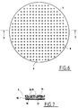
- a grinding wheel 1 according to FIGS. 1 to 3 and an adapter according to FIGS. 5 to 7 are now created.
- the general idea of the invention is expressed, for example, in FIGS. 1 to 3.
- the grinding body 1 is provided with a perforation 8, which is distributed over the entire surface, for example.
- the grinding wheel 1 can be formed from a wide variety of layers. This depends on the respective grinding process, quality of the ground layer and the material to be found. At least the layer 3 carrying the abrasive 2 is according to the invention penetrated by the perforations 9 forming the perforation 8.
- the abrasive body 1 according to the invention is formed from the layer 3 having the abrasive 2 and the layer 10 carrying the abrasive 2 or embedding the abrasive 2 and a Velcro adaptation layer 11, all of which are penetrated by the perforation 8.
- this can also be an auxiliary functional layer 12 arranged between the layer 3 containing the abrasive 2 or its carrier or embedding layer 10 and the Velcro adaptation layer 11, which can be present, for example, as a foam body for the purpose of elastic adaptation and compensation, but also as a temperature barrier layer.
- This can also be produced for wet or dry grinding designs.
- all the layers forming the grinding body 1 can be penetrated by a common perforation or only individual layers can be penetrated by this.
- auxiliary function layer 12 has no perforation 8, but communication channels 13 between the perforations 9 of the perforation 8 and the through their own foam-like structure Suction devices 7 of the grinding plate 5 forms. It goes without saying that both the perforation 8 and the communication channels 13 can flow through both gas and particles. The same also applies to the construction of the adapter according to FIGS. 6 to 7.
- the adapter 4 also provides the perforation 8 here, which, if the adapter 4 consists of a Velcro adaptation layer 14, only penetrates through it when a foam particle layer 15 is also shown, as shown here a subsequent velor layer 16, which can itself be flowed through.
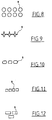
- FIG. 8 shows a perforation 8 which is formed from circular openings.
- FIG. 9 shows star-shaped openings 9 and FIG. 10 polygonal openings 9. These openings can be symmetrical like the square, rectangular or triangular openings according to FIGS. 11 to 13 or also of asymmetrical shape.
- FIG. 14 shows oval openings 9. The choice of the geometric shape is determined by the respective application. Thus, slot-like openings 9 in a linear (FIG. 15) or arc-shaped alignment (FIG. 16) are also possible.
- the essence of the invention is determined, inter alia, by the perforations in the grinding wheel and in the adapter or their layer structure. It was thus recognized that both the grinding wheel and the adapter can be used separately or in combination with one another.
- the adapter according to the invention can even be used with conventional Abrasive bodies having perforations can be used in the sense of the inventive concept.
Abstract
Description
Die Erfindung betrifft einen Schleifkörper, sowie einen zum arbeitsgerechten Aufbringen auf einen Maschinenschleifteller oder Schleifplatte bzw. auf einen betätigbaren Schleifmittelhalter mit oder ohne Absaugung, geeigneten Adapter nach dem Oberbegriff des Hauptanspruchs der Nebenansprüche und des Anspruchs 27, die getrennt oder in Kombination verwendbar sind.The invention relates to an abrasive body, as well as a suitable for application to a machine grinding plate or grinding plate or to an actuatable abrasive holder with or without suction, suitable adapter according to the preamble of the main claim, the independent claims and claim 27, which can be used separately or in combination.
Schleifkörper, insbesondere maschinenadaptierbare Schleifköper, sind in den vielfältigsten Ausführungsformen, hinsichtlich Aufbau und geometrischer Form bekannt.Abrasive bodies, in particular machine-adaptable abrasive bodies, are known in the most varied of embodiments with regard to structure and geometric shape.
Um ein einwandfreies Schleifergebnis zu erzielen, bedarf es des kontinuierlichen Abtransports des Schleifstaubes. Ist ein solcher Abtransport des Schleifstaubes nicht vorhanden oder wird ein solcher Abtransport nur unzureichend vorgenommen, führt dies zum Zusetzen der Schleifscheibe, so daß z.B. das einzelne Schleifkorn nicht mehr wirksam werden kann. Die Folge hieraus ist ein nicht zufriedenstellendes Schleifergebnis und eine beträchtlich verkürzte Standzeit des Schleifkörpers.In order to achieve a perfect sanding result, the sanding dust must be continuously removed. If there is no such removal of the grinding dust or if such removal is insufficient, this leads to clogging of the grinding wheel, so that e.g. the individual abrasive grain can no longer take effect. The result of this is an unsatisfactory grinding result and a considerably shortened service life of the grinding wheel.
Die Konsequenz hieraus war beispielsweise die Anordnung von Absaugeinrichtungen im Schleifteller oder der Schleifplatte der Maschine, wobei der Schleifkörper mit Mitteln versehen wurde, so daß die Absaugung theoretisch dadurch erfüllt werden sollte, in dem sich im Schleifkörper befindliche Lochungen mit den Absaugkanälen des Schleiftellers oder der Platte überragten. Diese Maßnahmen gelten auch für manuell nutzbare Schleifmittelhalter, die mit Absaugeinrichtungen versehen sein können.The consequence of this was, for example, the arrangement of suction devices in the grinding plate or the grinding plate of the machine, the grinding element being provided with means so that the suction should theoretically be achieved by perforations in the grinding element with the suction channels of the grinding plate or plate towered. These measures also apply to manually usable abrasive holders that can be equipped with suction devices.
Nun ist es aber, um eine grundlegende Funktion sicherzustellen, erforderlich, daß der Anwender den Schleifkörper mit seinen Durchbrechungen deckungsgleich zu den Ansaugkanälen des Schleiftellers bzw. der Schleifplatte oder den weiteren Werkzeughilfsmittel aufbringt, worauf aber erfahrungsgemäß bei den meisten Anwendern nicht geachtet wird. Noch schwieriger erweist sich die Erfüllung dieser Voraussetzung, wenn zwischen Schleifkörper und Schleifteller bzw. Schleifplatte oder Schleifklotz oder ähnlichem ein Adapterteil zuzuordnen ist. In der Praxis ist jedoch auch bei vorschriftsmäßiger Übereinanderanordnung der adaptierten Teile kein zufriedenstellender Abtransport des Schleifstaubes zu erwarten. Der Schleifstaub wird nämlich nicht dort aufgesaugt oder abtransportiert, wo er entsteht, sondern dort wo er durch die Rotation oder Oszillationsbewegung des Schleifkörpers unter die Ansauglochungen transportiert wird.
Zwischenzeitlich wird der Schleifstaub sowohl auf dem Werkstück verrieben als auch in die Schleiffläche gepreßt, wo er zum Zusetzen der Schleifmittel führt. Dies führt letztendlich zu einem qualitativ nicht zufriedenstellenden Schleifergebnis.Now, in order to ensure a basic function, it is necessary that the user applies the grinding body with its openings congruent to the suction channels of the grinding plate or the grinding plate or the other tool aids, but experience has shown that most users do not pay attention to this. This proves to be even more difficult if an adapter part is to be assigned between the grinding body and the grinding plate or grinding plate or grinding block or the like. In practice, however, a satisfactory removal of the grinding dust is not to be expected even when the adapted parts are arranged one above the other in accordance with the regulations. The grinding dust is not sucked up or removed where it is created, but where it is transported under the suction holes by the rotation or oscillation of the grinding wheel.
In the meantime, the grinding dust is both ground on the workpiece and pressed into the grinding surface, where it leads to clogging of the abrasives. This ultimately leads to an unsatisfactory grinding result.
Der vorliegenden Erfindung liegt daher die Aufgabe zugrunde, einen Schleifkörper sowie entsprechende Adaptionsmittel für Maschinen oder manuelle Werkzeuge zu schaffen, der dem geschilderten Nachteil des Standes der Technik wirkungsvoll entgegentritt und dabei einen kontinuierlichen, regelmäßigen und zufriedenstellenden Abtransport des Schleifstaubes sicherstellt, welche sowohl einzeln als auch im Kombination miteinander verwendbar sind.The present invention is therefore based on the object of providing a grinding wheel and corresponding adaptation means for machines or manual tools, which effectively counteracts the described disadvantage of the prior art and thereby ensures continuous, regular and satisfactory removal of the grinding dust, both individually and can be used in combination.
Dies wird erfindungsgemäß durch einen Schleifkörper nach dem Kennzeichen des vorgeschlagenen Hauptanspruches bzw. der Nebenansprüche sowie durch einen Adapter nach dem Kennzeichen des vorgeschlagenen Anspruchs 27 gelöst.According to the invention, this is solved by a grinding wheel according to the characterizing part of the proposed main claim or the secondary claims and by an adapter according to the characterizing part of the proposed claim 27.
Besonders bevorzugte Weiterbildungen der Erfindung sind in den Unteransprüchen gekennzeichnet.Particularly preferred developments of the invention are characterized in the subclaims.
Erfindungsgemäß weist nun sowohl der Schleifkörper als auch der für manche arbeitsgerechte Befestigungen verwendete Adapter ein Netz von Durchbrechungen auf, die sowohl untereinander, d.h. miteinander kommunizieren, als auch beispielsweise mit der Absaugeinrichtung der Maschine in Verbindung stehen, so daß sowohl die Absaugluft als auch der Partikelstrom wirksam wird und der Staub abgefördert werden kann.According to the invention, both the grinding wheel and the adapter used for some work-related fastenings now have a network of openings which are mutually, i.e. communicate with each other, as well as, for example, in connection with the suction device of the machine, so that both the suction air and the particle flow become effective and the dust can be removed.
Je nach dem,wie der Aufbau des Schleifkörpers gewählt ist, ist es ausreichend,die Perforation in einer Schicht des Schleifkörpers anzuordnen, wenn die darunter oder darüberliegende Schicht gas- und partikeldurchlässig ist. Bei wiederum anderen Schleifkörpern, mit anders geartetem Schichtaufbau kann es sinnvoll sein, die Perforation nicht durch eine,sondern durch mehrere oder alle Schichten, durchdringen zu lassen.Depending on how the structure of the grinding wheel is chosen, it is sufficient to arrange the perforation in one layer of the grinding wheel if the layer below or above it is gas and particle permeable. In the case of other grinding wheels, with a different layer structure, it may make sense not to let the perforation penetrate through one, but through several or all layers.
Gleiches gilt für den Aufbau des Adapters.The same applies to the construction of the adapter.
Daher zeichnet sich die vorliegende Erfindung dadurch aus, daß mittels dieser einerseits ein maschinenadaptierbarer Schleifkörper gebildet ist, der mindestens aus einer das Schleifmittel aufweisenden Schicht besteht und der direkt oder mit Hilfe eines Adapters indirekt auf den Schleifteller oder die Schleifplatte der Maschine arbeitsgerecht befestigbar ist und bei denen Mittel vorgesehen sind, die mit Absaugeinrichtungen des Schleiftellers oder der Schleifplatte der Maschine zusammenwirken können, wobei das Wesen der vorliegenden Erfindung darin liegt, daß mindestens der Schleifkörper eine Perforation aufweist, die annähernd gleichmäßig über die gesamte Fläche des Schleifkörpers verteilt oder zumindest partiell angeordnet ist und zumindest die das Schleifmittel aufweisende Schicht durchdringt, wobei der Abstand der einzelnen, die Perforation bildenden Durchbrechungen zueinander und gegenüber den Absaugeinrichtungen des Schleiftellers oder der Schleifplatte so angeordnet sind, daß ein nahezu stauloser Transport des Schleifstaubes bewirkt ist.Therefore, the present invention is characterized in that, on the one hand, a machine-adaptable grinding wheel is formed by means of this grinding wheel, which consists of at least one layer containing the abrasive and which is applied directly or indirectly with the aid of an adapter The grinding plate or the grinding plate of the machine can be fastened to suit the work and in which means are provided which can cooperate with suction devices of the grinding plate or the grinding plate of the machine, the essence of the present invention being that at least the grinding body has a perforation which is approximately uniformly above the entire surface of the grinding body is distributed or at least partially arranged and at least penetrates the layer containing the abrasive, the spacing of the individual perforations forming the perforations from one another and from the suction devices of the grinding plate or the grinding plate being arranged in such a way that an almost jam-free transport of the Grinding dust is caused.
Andererseits wird durch die vorliegende Erfindung ein Schleifkörper bereitgestellt, der auf einem manuell betätigbaren Schleifmittelhalter aufbringbar ist, welcher ebenfalls mit Absaugeinrichtungen bestückt ist und an eine externe Absauganlage gekoppelt wird.On the other hand, the present invention provides an abrasive body which can be applied to a manually operated abrasive holder, which is also equipped with suction devices and is coupled to an external suction system.
Erfindungsgemäß zeichnet dieser Schleifkörper dadurch aus, daß er mindestens aus einer das Schleifmittel aufweisenden Schicht besteht und der direkt oder mit Hilfe eines Adapters indirekt auf einen Schleifmittelhalter arbeitsgerecht befestigbar ist und bei dem ferner Mittel vorgesehen sind, die mit Absaugeinrichtungen des Schleifmittelhalters zusammenwirken können. Das Wesen dieses Schleifkörpers ist dadurch gekennzeichnet, daß mindestens der Schleifkörper eine Perforation aufweist, die annähernd gleichmäßig über die gesamte Fläche des Schleifkörpers verteilt oder zumindest partiell angeordnet ist und zumindest die das Schleifmittel aufweisende Schicht durchdringt, wobei der Abstand der einzelnen, die Perforation bildenden Durchbrechungen zueinander und gegenüber den Absaugeinrichtungen des Schleifmittelhalters so angeordnet sind, daß ein nahezu staubloser Transport des Schleifstaubes bewirkt ist.According to the invention, this abrasive is characterized in that it consists of at least one layer containing the abrasive and that can be directly or indirectly attached to an abrasive holder with the help of an adapter and in which means are also provided which can interact with suction devices of the abrasive holder. The essence of this grinding wheel is characterized in that at least the grinding wheel has a perforation which is approximately uniformly distributed over the entire surface of the grinding wheel or at least partially arranged and at least penetrates the layer containing the abrasive, the spacing of the individual perforations forming the perforations being arranged with respect to one another and with respect to the suction devices of the abrasive holder such that the grinding dust is transported almost without dust.
Ferner wird durch die Erfindung ein Schleifkörper geschaffen, der ohne Absaugeinrichtungen einen zufriedenstellenden Abtransport des Schleifstaubes bewirkt. Es wurd erkannt, daß durch das Vorhandensein der Perforation der Schleifstaub alleine durch den Anpreßdruck von der Schleiffläche entfernt und in Zonen und Schichten hinter der Schleifebene gedrängt wird. Somit ist ein Zusetzen der Schleifkörner nahezu vermieden.Furthermore, the invention provides a grinding wheel which effects a satisfactory removal of the grinding dust without suction devices. It was recognized that the presence of the perforation removes the grinding dust from the grinding surface solely by the contact pressure and forces it into zones and layers behind the grinding plane. Clogging of the abrasive grains is almost avoided.
Bei einer besonders bevorzugten Ausführungsform ist vorgesehen, daß auch der Adapter eine mit der Perforation des Schleifkörpers zusammenwirkende Perforation aufweist.In a particularly preferred embodiment it is provided that the adapter also has a perforation which interacts with the perforation of the grinding wheel.
Eine erste besonders bevorzugte Ausführungsvorm der vorliegenden Erfindung sieht einen Schleifkörper vor, der aus der das Schleifmittel aufweisenden Schicht und/oder der das Schleifmittel tragenden oder das Schleifmittel einbettenden Schicht und/oder der Klettadaptionsschicht besteht, die gemeinsam von der Perforation durchdrungen sind.
Zwischen der das Schleifmittel aufweisenden Schicht oder deren Träger oder Einbettungsschicht und der Klettadaptionsschicht kann eine Hilfsfunktionsschicht angeordnet sein. Solche Hilfsfunktionsschichten können als elastische Anpassungsschichten oder Ausgleichsschichten, beispielsweise aus Schaumstoff gebildet sein. Diese Hilfsfunktionsschichten können aber auch eine Temperatursperrwirkung besitzen und sowohl für den Naßals auch für den Trockenschliff geeignet sein. Bevorzugterweise sind alle den Schleifkörper bildenden Schichten von einer gemeinsamen Perforierung durchsetzt. Jedoch insbesondere,wenn die Hilfsfunktionschicht aus einem schaumartigen Aufbau besteht, sieht diese keine Perforation vor, sondern bildet selbst durch ihren schaumartigen Aufbau Kommuniktions- und Transportkanäle, zwischen den Durchbrechungen der Perforation der benachbarten Schicht und den Absaugeinrichtungen des Schleiftellers oder der verwendeten Werkzeuge. Die Perforation als auch die Kommunikationskanäle sind dabei gas- und partikeldurchströmbar.A first particularly preferred embodiment of the present invention provides an abrasive body which consists of the layer containing the abrasive and / or the layer carrying or embedding the abrasive and / or the Velcro adaptation layer, which are penetrated together by the perforation.
An auxiliary functional layer can be arranged between the layer containing the abrasive or its carrier or embedding layer and the Velcro adaptation layer. Such auxiliary function layers can be formed as elastic adaptation layers or compensation layers, for example made of foam. This Auxiliary function layers can also have a temperature blocking effect and be suitable for both wet and dry grinding. All the layers forming the grinding wheel are preferably penetrated by a common perforation. However, in particular if the auxiliary functional layer consists of a foam-like structure, it does not provide any perforation, but rather forms communication and transport channels through its foam-like structure, between the perforations in the adjacent layer and the suction devices of the grinding plate or the tools used. The perforation as well as the communication channels can flow through gas and particles.
Die Formen der die Perforation bildenden Durchbrechungen können sowohl kreisförmig, eckig und oval sein. Sie können auch durch schlitzartige Durchbrechungen, welche linear oder bogenförmig ausgerichtet sind, gebildet werden. Dies gilt sowohl für die Perforation des Schleifkörpers,als auch für die Perforation des Adapters. Sowohl der Schleifkörper als auch der Adapter kann scheibenförmig, kreisrund, eckig, d.h. rechteckig oder dreieckig oder auch sternförmig ausgebildet sein. Der Schleifmittelträger besteht aus Papier, Gewebe oder einem Vlies.The shapes of the perforations forming the perforation can be circular, angular and oval. They can also be formed by slit-like openings which are aligned linearly or in an arc shape. This applies to both the perforation of the grinding wheel and the perforation of the adapter. Both the grinding wheel and the adapter can be disc-shaped, circular, angular, i.e. be rectangular or triangular or star-shaped. The abrasive backing consists of paper, fabric or a non-woven.
Die vorliegende Erfindung stellt auch einen Adapter bereit, der zu arbeitsgerechten Maschinen- oder Schleifmittelhalteranordnung eines konventionellen als auch eines Schleifkörpers nach den Ansprüchen 1 bis 26 geeignet ist und kennzeichnet sich dadurch, daß der Adapter aus einer Klettadaptionsschicht, einer Schaumpartikelschicht und einer Veloursschicht besteht, wobei die zum Schleifkörper hinweisende Klettadaptionsschicht mit von der Perforation durchdrungen ist. Die Perforation als solche, sowohl im Schleifkörper als auch im Adapter ist erfindungsgemäß dort anzuordnen, wo die Schicht als solche gas- oder partikelstromundurchlässig ist. Die Eigenschaft des Schleifkörpers hinsichtlich Aufbau und Schichten, mit Ausnahme der Schleifschicht, gelten auch für die des Adapters.The present invention also provides an adapter which is suitable for a machine or abrasive holder arrangement of a conventional as well as an abrasive body according to
Anhand den beigefügten Zeichnungen, die besonders bevorzugte Ausführungsbeispiele der Erfindung zeigen, wird diese nun näher beschrieben.
Dabei zeigen:
Figur 1- eine Draufsicht auf eine erste Ausführungsvariante der vorliegenden Erfindung, hier eine mit Klettadaptionsfläche versehene Schleifscheibe
Figur 2- das in
Figur 1 mit A gekennzeichnete Detail in einer Vergrößerung; - Figur 3
- einen Schnitt entlang der in
Figur 2 angedeuteten Linie B-B in einer Vergrößerung; - Figur 4
- eine Seitenansicht eines Schleiftellers;
- Figur 5
- die Unterseite des Schleiftellers nach Figur 4 aus der in Figur 4 angedeuteten Richtung C;
Figur 6- einen Adapter in der Draufsicht auf die Klettadaptionsfläche;
Figur 7- einen Schnitt entlang der in
Figur 6 angedeuteten Linie D-D, wobei der geschnittene Adapter 4 nur in einem Teilbereich, und zwar in vergrößerter Darstellung gezeigt ist. Figuren 8 bis 16- verschiedene Varianten der Perforationsbildung.
Show:
- Figure 1
- a plan view of a first embodiment of the present invention, here a grinding wheel provided with Velcro adaptation surface
- Figure 2
- the detail marked with A in Figure 1 in an enlargement;
- Figure 3
- a section along the line BB indicated in Figure 2 in an enlargement;
- Figure 4
- a side view of a grinding plate;
- Figure 5
- the underside of the grinding plate according to Figure 4 from the direction C indicated in Figure 4;
- Figure 6
- an adapter in plan view of the Velcro adaptation surface;
- Figure 7
- a section along the line DD indicated in Figure 6, the cut adapter 4 is shown only in a partial area, namely in an enlarged view.
- Figures 8 to 16
- different types of perforation.
Zunächst wird auf die Figuren 4 und 5 Bezug genommen. Die Figuren 4 und 5 zeigen einen Schleifteller 5, der mit Absaugeinrichtungen 7, hier einzelne radial angeordnete Bohrungen, ausgestattet ist. Über diese Absaugeinrichtungen 7 wird herkömmlicherweise der abgetragene Schleifstaub einem Auffangbeutel zugeführt, wobei die eigentliche Saugeinrichtung am oder im Schleifgerät integriert ist. Diese Darstellung ist stellvertretend für eine Schleifplatte oder einen sonstigen Schleifmittelhalter 6 mit oder ohne Absaugeinrichtungen.First, reference is made to FIGS. 4 and 5. Figures 4 and 5 show a grinding plate 5, which is equipped with
Es gilt nun erfindungsgemäß die funktionsgerechte Zuführung des Schleifstaubes zu diesen Absaugeinrichtungen 7 oder den gleichwertigen Abtransport sicherzustellen. Herkömmlicherweise sind hierzu die Schleifmittel, beispielsweise kreisrunde Schleifscheiben, ebenfalls mit Durchbrechungen versehen, die deckungsgleich zu den Absaugeinrichtungen 7 aufzubringen sind. Wie eingangs bereits erwähnt, kann dieser Stand der Technik nicht sicherstellen, daß das Schleifergebnis zufriedenstellend ausfällt. Der Grund hierfür liegt im eigentlichen System. Der Schleifteller 5 besitzt eine Klettadaptionsfläche 17. Darüber befindet sich eine druck- und stoßausgleichende weichere Schicht 18. Sowohl letztere Schicht als auch die Perforationsfläche sind fest auf einem Tragteller 19 aufgebracht, welcher ein Verbindungselement 20 zur Maschine besitzt. Sowohl die Klettadaptionsfläche 17 als auch die weiche Schicht 18 und der Tragteller 19 des Schleiftellers sind von den Absaugeinrichtungen 7 in Form von Durchbrechungen oder Bohrungen durchsetzt.According to the invention, it is now a matter of ensuring the functionally appropriate feeding of the grinding dust to these
Wird nun der Schleifkörper 1 unsachgemäß auf den Schleifteller 5 aufgebracht, d.h. wenn die herkömmlichen mit den Absaugeinrichtungen 7 deckungsgleichen Bohrungen der Schleifscheibe nicht exakt über die Absaugeinrichtung 7 positioniert werden, ist die Absaugung des Schleifstaubes zunichte gemacht.
Aber auch dann, wenn die Schleifscheibe ordnungsgemäß positioniert wird, ist eine kontinuierliche Absaugung aus den bereits genannten Gründen nicht gewährleistet.If the grinding
But even if the grinding wheel is properly positioned, continuous extraction is not guaranteed for the reasons already mentioned.
Erfindungsgemäß wird nun ein Schleifkörper 1 gemäß Figur 1 bis 3 sowie ein Adapter gemäß den Figuren 5 bis 7 geschaffen. Der allgemeine Erfindungsgedanke drückt sich beispielsweise in den Figuren 1 bis 3 aus. Erfindungsgemäß ist der Schleifkörper 1 mit einer Perforation 8 versehen, die sich beispielsweise über die gesamte Fläche verteilt. Der Schleifkörper 1 kann dabei aus verschiedensten Schichten gebildet werden. Dies ist abhängig vom jeweiligen Schleifverfahren, Güte der beschliffenen Schicht und dem anzutreffenden Material. Zumindest ist erfindungsgemäß die das Schleifmittel 2 tragende Schicht 3 von den die Perforation 8 bildenden Durchbrechungen 9 durchsetzt. Durch diese erfindungsgemäße Anordnung der Durchbrechungen 9 der Perforation 8 zueinander sowie gegenüber den Absaugeinrichtungen 7 des Schleiftellers 5 ist ein nahezu stauloser Transport des Schleifstaubes zu den Absaugeinrichtungen 7 bewirkt. Beispielsweise ist der erfindungsgemäße Schleifkörper 1, aus der das Schleifmittel 2 aufweisenden Schicht 3 und der das Schleifmittel 2 tragenden oder das Schleifmittel 2 einbettenden Schicht 10 und einer Klettadaptionsschicht 11 gebildet, die alle durch die Perforation 8 durchdrungen sind.According to the invention, a
Es kommen also Schleifkörper für diese Erfindung in Frage, bei denen der unterschiedlichste Schichtaufbau möglich ist. Beispielsweise kann dies auch gemäß Figur 3a eine zwischen der das Schleifmittel 2 aufweisenden Schicht 3 oder deren Träger oder Einbettungsschicht 10 und der Klettadaptionsschicht 11 angeordnete Hilfsfunktionsschicht 12 sein, die beispielsweise als Schaumkörper zum Zwecke der elastischen Anpassung und des Ausgleiches aber auch als Temperatursperrschicht vorliegen kann. Diese ist ebenfalls für Naß- oder Trockenschliffausführungen herstellbar.
Wie zuvor dargelegt, können alle den Schleifkörper 1 bildenden Schichten von einer gemeinsamen Perforation durchsetzt sein oder auch nur einzelne Schichten von dieser durchsetzt werden.
Eine Ausführungsform der vorliegenden Erfindung besteht darin, daß die Hilfsfunktionsschicht 12 keine Perforation 8 aufweist, sondern durch ihren eigenen schaumartigen Aufbau Kommunikationskanäle 13 zwischen den Durchbrechungen 9 der Perforation 8 und den Absaugeinrichtungen 7 des Schleiftellers 5 bildet. Es versteht sich hierbei, daß sowohl die Perforation 8 als auch die Kommunikationskanäle 13 sowohl gas- als auch partikeldurchströmbar sind. Gleiches gilt auch für den Aufbau des Adapters gemäß den Figuren 6 bis 7. Der Adapter 4 sieht auch hier die Perforation 8 vor, die, falls der Adapter 4 aus einer Klettadaptionsschicht 14 besteht, lediglich diese durchsetzt, wenn wie hier gezeigt eine Schaumpartikelschicht 15 mit einer darauf folgenden Veloursschicht 16, welche selbst durchströmbar sind, besteht.So there are grinding wheels for this invention in which the most varied layer structure is possible. For example, according to FIG. 3a, this can also be an auxiliary
As explained above, all the layers forming the grinding
An embodiment of the present invention is that the
Figur 8 zeigt eine Perforation 8 die aus kreisrunden Durchbrechungen gebildet ist. Figur 9 zeigt sternförmige durchbrechungen 9 und Figur 10 vieleckige Durchbrechungen 9. Diese Durchbrechungen können symmetrisch wie die quadratischen, rechteckigen oder dreieckigen Durchbrechungen gemäß den Figuren 11 bis 13 oder auch von assymetrischer Formgebung sein. Die Figur 14 zeigt ovale Durchbrechungen 9. Die Wahl der geometrischen Form wird durch den jeweiligen Anwendungsfall bestimmt. So kommen auch schlitzartige Durchbrechungen 9 in lineare (Figur 15) oder bogenförmige Ausrichtung (Figur 16) in Betracht. Das Wesen der Erfindung wird u.a. durch die Perforationen im Schleifkörper und im Adapter bzw. deren Schichtaufbau bestimmt. So wurde erkannt, daß sowohl der Schleifkörper als auch der Adapter separat oder auch in Kombination miteinander genutzt werden können. Der erfindungsgmäße Adapter kann sogar mit herkömmlichen,
Lochungen aufweisenden Schleifkörpern im Sinne des Erfindungsgedankens genutzt werden.FIG. 8 shows a
Abrasive bodies having perforations can be used in the sense of the inventive concept.
- 11
- SchleifkörperGrinding wheel
- 22nd
- SchleifmittelAbrasives
- 33rd
- Schicht für 2 (tragend)Layer for 2 (load-bearing)
- 44th
- Adapteradapter
- 55
- Schleifteller/SchleifplatteSanding disc / plate
- 66
- SchleifmittelhalterAbrasive holder
- 77
- AbsaugeinrichtungSuction device
- 88th
- Perforationperforation
- 99
- Durchbrechungen von 8Breakthroughs of 8
- 1010th
- Schicht für 2 (einbettend)Layer for 2 (embedding)
- 1111
- Klettadaptionsschicht von 1Velcro adaptation layer from 1
- 1212th
- HilfsfunktionsschichtAuxiliary function layer
- 1313
- Kommunikationskanäle von 12/15Communication channels from 12/15
- 1414
- Kleppadaptionsschicht von 4Kleppadaptionsschicht of 4
- 1515
- Schaumpartikelschicht von 4Foam particle layer from 4
- 1616
- Veloursschicht von 4Velor layer from 4
- 1717th
- Klettadaptionsfläche von 5Velcro adaptation area of 5
- 1818th
- Zwischenschicht von 5Intermediate layer of 5
- 1919th
- Tragteller von 5Carrying plate from 5
- 2020th
- Verbindungselement von 5Connection element of 5
Claims (30)
dadurch gekennzeichnet,
daß mindestens der Schleifkörper (1) eine Perforation (8) aufweist, die annähernd gleichmäßig über die gesamte Fläche des Schleifkörpers (1) verteilt oder zumindest partiell angeordnet ist und zumindest die das Schleifmittel (2) aufweisende Schicht (3) durchdringt, wobei der Abstand der einzelnen, die Perforation (8) bildenden Durchbrechungen (9) zueinander und gegenüber den Absaugeinrichtungen (7) des Schleiftellers oder der Schleifplatte (5) so angeordnet sind, daß ein nahezu stauloser Transport des Schleifstaubes bewirkt ist.Abrasive body, at least consisting of a layer containing the abrasive, which can be fastened directly or with the help of an adapter indirectly to the sanding plate or the sanding plate of the machine and in which means are provided which can interact with suction devices of the sanding plate of the machine,
characterized,
that at least the abrasive body (1) has a perforation (8) which is distributed approximately uniformly over the entire surface of the abrasive body (1) or at least partially arranged and at least penetrates the layer (3) containing the abrasive (2), the distance of the individual perforations (9) forming the perforations (8) to one another and to the suction devices (7) of the sanding plate or the sanding plate (5) are arranged in such a way that the sanding dust is transported almost without traffic jams.
dadurch gekennzeichnet,
daß mindestens der Schleifkörper (1) eine Perforation (8) aufweist, die annähernd gleichmäßig über die gesamte Fläche des Schleifkörpers (1) verteilt oder zumindest partiell angeordnet ist und zumindest die das Schleifmittel (2) aufweisende Schicht (3) durchdringt, wobei der Abstand der einzelnen, die Perforation (8) bildenden Durchbrechungen (9) zueinander und gegenüber den Absaugeinrichtungen (7) des Schleifmittelhalters (6) so angeordnet sind, daß ein nahezu stauloser Transport des Schleifstaubes bewirkt ist.Abrasive body, at least consisting of a layer containing the abrasive, which can be fastened directly or indirectly with the help of an adapter on an abrasive holder and in which the means are provided which can interact with suction devices of the abrasive holder,
characterized,
that at least one of the grinding wheels (1) Has perforation (8) which is approximately uniformly distributed over the entire surface of the grinding body (1) or at least partially arranged and at least penetrates the layer (3) containing the abrasive (2), the distance between the individual, the perforation (8) Breakthroughs (9) forming one another and opposite the suction devices (7) of the abrasive holder (6) are arranged in such a way that the sanding dust is transported almost without traffic jams.
dadurch gekennzeichnet,
daß mindestens der Schleifkörper (1) eine Perforation (8) aufweist, die annähernd gleichmäßig über die gesamte Fläche des Schleifkörpers verteilt oder zumindest partiell angeordnet ist und zumindest die das Schleifmittel (2) aufweisende Schicht (3) durchdringt, wobei der Abstand der einzelnen, die Perforation (8) bildenden Durchbrechungen (9) zueinander so gewählt ist, daß ein nahezu stauloser Transport des Schleifstaubes bewirkt ist.Abrasive body, at least consisting of a layer containing the abrasive, which can be attached to the abrasive holder directly or indirectly with the help of an adapter,
characterized,
that at least the abrasive body (1) has a perforation (8) which is approximately uniformly distributed over the entire surface of the abrasive body or at least partially arranged and at least penetrates the layer (3) containing the abrasive (2), the distance between the individual, the perforations (9) forming the perforations (8) in relation to one another are selected such that the grinding dust is transported almost without traffic jams.
dadurch gekennzeichnet,
daß der Adapter (4) eine mit der Perforation des Schleifkörpers (1) zusammenwirkende Perforation (8) aufweist.Abrasive body according to claims 1 to 3,
characterized,
that the adapter (4) has a perforation (8) which interacts with the perforation of the grinding body (1).
dadurch gekennzeichnet,
daß ein Schleifkörper (1) aus der das Schleifmittel (2) aufweisenden Schicht (3) und/oder der das Schleifmittel (2) tragenden oder das Schleifmittel (2) einbettenden Schicht (10) und/oder der Klettadaptionsschicht (11) besteht, die gemeinsam von der Perforation (8) durchdrungen sind.Abrasive body according to claims 1 to 3,
characterized,
that an abrasive body (1) consists of the abrasive (2) layer (3) and / or the abrasive (2) or embedding the abrasive (2) layer (10) and / or the Velcro adaptation layer (11), which are penetrated together by the perforation (8).
dadurch gekennzeichnet,
daß zwischen der das Schleifmittel (2) aufweisenden Schicht (3) oder deren Träger- oder Einbettungsschicht (10) und der Klettadaptionsschicht (11) eine Hilfsfunktionsschicht (12) angeordnet ist.Abrasive body according to claims 1 to 5,
characterized,
that an auxiliary functional layer (12) is arranged between the layer (3) having the abrasive (2) or its carrier or embedding layer (10) and the Velcro adaptation layer (11).
Anspruch 6,
dadurch gekennzeichnet,
daß die Hilfsfunktionsschicht (12) als elastische Anpassungsschicht oder Ausgleichsschicht ausgebildet ist.Grinding wheel after
Claim 6
characterized,
that the auxiliary function layer (12) is designed as an elastic adaptation layer or compensation layer.
dadurch gekennzeichnet,
daß die Hilfsfunktionsschicht (12) als Temperatursperrschicht ausgebildet ist.Abrasive body according to at least one of the preceding claims,
characterized,
that the auxiliary function layer (12) is designed as a temperature barrier layer.
1 bis 8,
dadurch gekennzeichnet,
daß die Hilfsfunktionsschicht (12) zum Naß- und/oder Trockenschliff geeignet ist.Abrasive body according to claim
1 to 8,
characterized,
that the auxiliary function layer (12) is suitable for wet and / or dry grinding.
1 bis 9,
dadurch gekennzeichnet,
daß die den Schleifkörper (1) bildenden Schichten eine gemeinsame Perforation (8) aufweisen.Abrasive body according to claim
1 to 9,
characterized,
that the layers forming the grinding body (1) have a common perforation (8).
1 bis 9,
dadurch gekennzeichnet,
daß die Hilfsfunktionsschicht (12) keine Perforation (8) aufweist und durch einen schaumartigen Aufbau Kommunikationskanäle (13) zwischen den Durchbrechungen (9) der Perforation (8) der benachbarten Schicht und den Ansaugeinrichtungen (7) des Schleiftellers oder Schleifplatte (5) oder Schleifmittelhalter (6) bildet.Abrasive body according to claim
1 to 9,
characterized,
that the auxiliary functional layer (12) has no perforation (8) and through a foam-like structure communication channels (13) between the perforations (9) of the perforation (8) of the adjacent layer and the suction devices (7) of the grinding plate or grinding plate (5) or abrasive holder (6) forms.
1 bis 11,
dadurch gekennzeichnet,
daß sowohl die Perforation (8) als auch die Kommunikationskanäle (13) gas- und partikeldurchströmbar sind.Abrasive body according to claim
1 to 11,
characterized,
that both the perforation (8) and the communication channels (13) can be flowed through by gas and particles.
dadurch gekennzeichnet,
daß die Perforation (8) durch kreisförmige Durchbrechungen (9) gebildet ist.Abrasive body according to claims 1 to 12,
characterized,
that the perforation (8) is formed by circular openings (9).
dadurch gekennzeichnet,
daß die Perforation (8) durch eckige Durchbrechungen (9) gebildet ist.Abrasive body according to claims 1 to 12,
characterized,
that the perforation (8) is formed by angular openings (9).
dadurch gekennzeichnet,
daß die Perforaton (8) durch ovale Durchbrechungen (9) gebildet ist.Abrasive body according to claims 1 to 12,
characterized,
that the perforation (8) is formed by oval openings (9).
dadurch gekennzeichnet,
daß die Perforation (8) durch schlitzartige Durchbrechungen (9) gebildet ist.Abrasive body according to claims 1 to 12,
characterized,
that the perforation (8) is formed by slot-like openings (9).
dadurch gekennzeichnet,
daß die die Perforation (8) bildenden schlitzartigen Durchbrechungen (9) linear ausgerichtet sind.Abrasive body according to claim 16,
characterized,
that the slot-like openings (9) forming the perforation (8) are aligned linearly.
dadurch gekennzeichnet,
daß die die Perforation (8) bildenden schlitzartigen Durchbrechungen (9) bogenförmig ausgerichtet sind.Abrasive body according to claim 16,
characterized,
that the slot-like openings (9) forming the perforation (8) are aligned in an arc.
dadurch gekennzeichnet,
daß dieser scheibenförmig ausgebildet ist.Abrasive body according to claims 1 to 18,
characterized,
that this is disc-shaped.
dadurch gekennzeichnet,
daß dieser kreisrund ausgebildet ist.Abrasive body according to claims 1 to 19,
characterized,
that this is circular.
dadurch gekennzeichnet,
daß dieser eckig ausgebildet ist.Abrasive body according to claims 1 to 19,
characterized,
that this is square.
dadurch gekennzeichnet,
daß dieser rechteckig ausgebildet ist.Abrasive body according to claim 21,
characterized,
that this is rectangular.
dadurch gekennzeichnet,
daß dieser dreieckig oder sternförmig ausgebildet ist.Abrasive body according to claim 21,
characterized,
that it is triangular or star-shaped.
dadurch gekennzeichnet,
daß der Schleifmittelträger aus Papier besteht.Abrasive body according to claims 1 to 23,
characterized,
that the abrasive backing is made of paper.
dadurch gekennzeichnet,
daß der Schleifmittelträger aus einem Gewebe besteht.Abrasive body according to claims 1 to 23,
characterized,
that the abrasive backing consists of a fabric.
dadurch gekennzeichnet,
daß der Schleifmittelträger aus Vlies besteht.Abrasive body according to claims 1 to 23,
characterized,
that the abrasive backing consists of fleece.
dadurch gekennzeichnet,
daß der Adapter (4) aus einer Klettadaptionsschicht (14), einer Schaumpartikelschicht (15) und einer Veloursschicht (16) besteht, wobei die zum Schleifkörper (1) hinweisende Klettadaptionsschicht (14) mit von der Perforation (8) durchdrungen ist.Adapter for the machine or abrasive holder arrangement appropriate to the work of a conventional as well as an abrasive body according to claims 1 to 26,
characterized,
that the adapter (4) consists of a Velcro adaptation layer (14), a foam particle layer (15) and a velor layer (16), the Velcro adaptation layer (14) pointing towards the abrasive body (1) being penetrated by the perforation (8).
dadurch gekennzeichnet,
daß die Schaumpartikelschicht (15) als Hilfsfunktionsschicht wirkend ausgebildet ist.Adapter according to claim 27,
characterized,
that the foam particle layer (15) is designed to act as an auxiliary functional layer.
dadurch gekennzeichnet,
daß die als Hilfsfunktionssschicht wirkend ausgebildete Schaumpartikelschicht (15) keine Perforation (8) aufweist und durch den schaumartigen Aufbau Kommunikationskanäle (13) zwischen den Durchbrechungen (9) der Perforation der benachbarten Schicht und den Ansaugeinrichtungen des Schleiftellers oder der Schleifplatte bzw. dem Schleifmittelhalter bildet.Adapter according to claim 18,
characterized,
that the foam particle layer (15) acting as an auxiliary functional layer has no perforation (8) and, through the foam-like structure, forms communication channels (13) between the perforations (9) of the perforation of the adjacent layer and the suction devices of the sanding plate or the sanding plate or the abrasive holder.
dadurch gekennzeichnet,
daß sowohl die Perforation (8) als auch die Kommunikationskanäle (13) gas- und partikeldurchströmbar sind.Adapter according to claim 27 to 29,
characterized,
that both the perforation (8) and the communication channels (13) can be flowed through by gas and particles.
Applications Claiming Priority (2)
| Application Number | Priority Date | Filing Date | Title |
|---|---|---|---|
| DE29520566U DE29520566U1 (en) | 1995-12-29 | 1995-12-29 | Abrasives that can be adapted directly or indirectly with a machine or a manually operated abrasive holder as well as a suitable adapter |
| DE29520566U | 1995-12-29 |
Publications (2)
| Publication Number | Publication Date |
|---|---|
| EP0781629A1 true EP0781629A1 (en) | 1997-07-02 |
| EP0781629B1 EP0781629B1 (en) | 1999-06-09 |
Family
ID=8017243
Family Applications (1)
| Application Number | Title | Priority Date | Filing Date |
|---|---|---|---|
| EP96106587A Expired - Lifetime EP0781629B1 (en) | 1995-12-29 | 1996-04-26 | Directly or indirectly adaptable grinding body for a machine or a manually operable grinding device holder, as well as a suitable adapter for same |
Country Status (7)
| Country | Link |
|---|---|
| US (1) | US5810650A (en) |
| EP (1) | EP0781629B1 (en) |
| AT (1) | ATE181010T1 (en) |
| DE (2) | DE29520566U1 (en) |
| DK (1) | DK0781629T3 (en) |
| ES (1) | ES2132803T3 (en) |
| GR (1) | GR3030560T3 (en) |
Cited By (10)
| Publication number | Priority date | Publication date | Assignee | Title |
|---|---|---|---|---|
| EP1186379B1 (en) * | 2000-09-07 | 2006-02-22 | Claudio Mazzolini | Device for surface grinding and sanding |
| EP1666204A1 (en) * | 2004-11-17 | 2006-06-07 | sia Abrasives Industries AG | Abrasive product |
| EP1733844A1 (en) * | 2005-06-13 | 2006-12-20 | Oy Kwh Mirka Ab | Flexible grinding product and method of producing the same |
| EP1775071A1 (en) | 2003-08-11 | 2007-04-18 | UFI Schleiftechnik GmbH & Co. KG | Abrasive disc for grinding machine |
| DE202010012502U1 (en) | 2010-09-13 | 2010-11-18 | Robert Bosch Gmbh | grinding wheel |
| DE102010003616A1 (en) | 2010-04-01 | 2011-10-06 | Robert Bosch Gmbh | Holding body for flexible abrasive and grinding system |
| DE102012216556A1 (en) | 2011-09-20 | 2013-03-21 | Robert Bosch Gmbh | Holding body for flexible abrasive, grinding system and grinder |
| WO2013072458A3 (en) * | 2011-11-17 | 2013-08-22 | Rud. Starcke Gmbh & Co. Kg | Flat, open-to-dust grinding element |
| DE102017216175A1 (en) | 2017-09-13 | 2019-03-14 | Robert Bosch Gmbh | abrasive article |
| DE102020125135A1 (en) | 2020-09-25 | 2022-03-31 | Jöst Gmbh | Grinding wheel, grinding device and use of a grinding wheel |
Families Citing this family (38)
| Publication number | Priority date | Publication date | Assignee | Title |
|---|---|---|---|---|
| US6575821B2 (en) | 2000-08-01 | 2003-06-10 | Joest Peter | Abrasive belt for a belt grinding machine |
| US7108594B2 (en) | 2001-03-16 | 2006-09-19 | Saint-Gobain Abrasives Technology Company | Perforated sanding disc |
| US6743086B2 (en) * | 2001-08-10 | 2004-06-01 | 3M Innovative Properties Company | Abrasive article with universal hole pattern |
| JP2003071731A (en) * | 2001-09-03 | 2003-03-12 | Three M Innovative Properties Co | Dimple structure abrasive material |
| US20040180618A1 (en) * | 2001-09-03 | 2004-09-16 | Kazuo Suzuki | Sheet-form abrasive with dimples or perforations |
| JP3843933B2 (en) * | 2002-02-07 | 2006-11-08 | ソニー株式会社 | Polishing pad, polishing apparatus and polishing method |
| FR2856323B1 (en) * | 2003-06-16 | 2007-03-23 | Marc Bottazzi | ABRASIVE DISC FOR ELECTROMAGNETIC MACHINE IN MEULER |
| US20060019579A1 (en) * | 2004-07-26 | 2006-01-26 | Braunschweig Ehrich J | Non-loading abrasive article |
| EP1838497B1 (en) * | 2004-12-30 | 2016-07-13 | 3M Innovative Properties Company | Abrasive article and methods of making same |
| JP2006289592A (en) * | 2005-04-14 | 2006-10-26 | Three M Innovative Properties Co | Sheet-like applying abrasive |
| US7258705B2 (en) * | 2005-08-05 | 2007-08-21 | 3M Innovative Properties Company | Abrasive article and methods of making same |
| US7252694B2 (en) * | 2005-08-05 | 2007-08-07 | 3M Innovative Properties Company | Abrasive article and methods of making same |
| US7390244B2 (en) * | 2005-09-16 | 2008-06-24 | 3M Innovative Properties Company | Abrasive article mounting assembly and methods of making same |
| US7244170B2 (en) * | 2005-09-16 | 2007-07-17 | 3M Innovative Properties Co. | Abrasive article and methods of making same |
| US7393269B2 (en) * | 2005-09-16 | 2008-07-01 | 3M Innovative Properties Company | Abrasive filter assembly and methods of making same |
| GB0610531D0 (en) * | 2006-05-30 | 2006-07-05 | 3M Innovative Properties Co | Abrading article comprising a slotted abrasive disc and a back-up pad |
| US7452265B2 (en) * | 2006-12-21 | 2008-11-18 | 3M Innovative Properties Company | Abrasive article and methods of making same |
| US8080072B2 (en) * | 2007-03-05 | 2011-12-20 | 3M Innovative Properties Company | Abrasive article with supersize coating, and methods |
| US7959694B2 (en) * | 2007-03-05 | 2011-06-14 | 3M Innovative Properties Company | Laser cut abrasive article, and methods |
| US7628829B2 (en) * | 2007-03-20 | 2009-12-08 | 3M Innovative Properties Company | Abrasive article and method of making and using the same |
| US20080318506A1 (en) * | 2007-06-19 | 2008-12-25 | John Edward Brown | Abrasive article and method of making |
| BRPI0821673A2 (en) * | 2007-12-31 | 2015-06-16 | Saint Gobain Abrasives Inc | Interface pad intended for use between an abrasive article and a support tool |
| US20090227188A1 (en) * | 2008-03-07 | 2009-09-10 | Ross Karl A | Vacuum Sander Having a Porous Pad |
| WO2010004601A1 (en) * | 2008-07-11 | 2010-01-14 | Power-Tech Srl | Abrasive member like abrasive sheet, strip, roll or belt for surface finishing or surface preparation of manufactured articles. |
| FR2954723B1 (en) * | 2009-12-29 | 2012-04-20 | Saint Gobain Abrasives Inc | ABRASIVE ARTICLE COMPRISING A HOLLOW SPACE BETWEEN ITS FRONT AND REAR FACES AND METHOD OF MANUFACTURE |
| DE102010002539A1 (en) | 2010-03-03 | 2011-09-08 | Jöst Gmbh | Abrasive body for use in sharpening plate of e.g. sanding sleeve of angle grinder for grinding cylindrical inner or outer surfaces of work-piece for construction of e.g. furniture, has filter froth exhibiting specific air permeability |
| JP5767325B2 (en) | 2010-07-02 | 2015-08-19 | スリーエム イノベイティブ プロパティズ カンパニー | Coated abrasive article |
| DE102010027616A1 (en) | 2010-07-20 | 2012-01-26 | Gottlieb Binder Gmbh & Co. Kg | Adhesive closure part and method for producing an adhesive closure part |
| US20120028553A1 (en) * | 2010-07-30 | 2012-02-02 | Saint-Gobain Abrasives, Inc. | Flexible abrasive grinding apparatus and related methods |
| WO2012020275A1 (en) * | 2010-08-10 | 2012-02-16 | Miksa Marton | Sanding apparatus |
| EP2422931A1 (en) * | 2010-08-31 | 2012-02-29 | Jöst GmbH | Universal grinding plate unit with suction hood for a rotating grinding machine |
| US10099343B2 (en) * | 2010-11-15 | 2018-10-16 | 3M Innovative Properties Company | Abrasive disc with universal hole pattern |
| CN104039508B (en) | 2011-12-29 | 2017-12-12 | 3M创新有限公司 | Coated abrasive article and preparation method thereof |
| WO2013102206A1 (en) | 2011-12-31 | 2013-07-04 | Saint-Gobain Abrasives, Inc. | Abrasive article having a non-uniform distribution of openings |
| DE202012013026U1 (en) | 2012-01-31 | 2014-07-15 | Robert Bosch Gmbh | unit |
| CN203210209U (en) * | 2013-04-03 | 2013-09-25 | 淄博理研泰山涂附磨具有限公司 | Anti-blocking mesh abrasive cloth |
| EP2957387A1 (en) | 2014-06-18 | 2015-12-23 | Hermes Schleifmittel GmbH & Co. KG | Adapter for attaching a grinding wheel on a support pad |
| US20210205946A1 (en) * | 2020-01-02 | 2021-07-08 | Andrew Trebino | Sanding Tool Attachment |
Citations (6)
| Publication number | Priority date | Publication date | Assignee | Title |
|---|---|---|---|---|
| US4937984A (en) * | 1989-02-23 | 1990-07-03 | Taranto Thomas F | Vacuum sander |
| US5007206A (en) * | 1989-10-05 | 1991-04-16 | Paterson Patrick J | Dustless drywall sander |
| US5036627A (en) * | 1989-06-28 | 1991-08-06 | David Walters | Dustless sanding device |
| EP0578865A1 (en) * | 1992-07-09 | 1994-01-19 | Norton Company | Abrasive tool |
| WO1996007509A1 (en) * | 1994-09-06 | 1996-03-14 | Oy Kwh Mirka Ab | Grinding product and method of making same |
| WO1996013358A1 (en) * | 1994-10-27 | 1996-05-09 | Minnesota Mining And Manufacturing Company | Abrasive articles and methods for their manufacture |
Family Cites Families (18)
| Publication number | Priority date | Publication date | Assignee | Title |
|---|---|---|---|---|
| US2749681A (en) * | 1952-12-31 | 1956-06-12 | Stephen U Sohne A | Grinding disc |
| FR1085962A (en) * | 1952-12-31 | 1955-02-08 | Stephan & Soehne | Grinding wheel |
| US2838890A (en) * | 1955-04-18 | 1958-06-17 | Kimberly Clark Co | Cellulosic product |
| US3021649A (en) * | 1959-02-04 | 1962-02-20 | Imp Foam Rubber Corp | Perforated abrasive faced scrubbing pad |
| FR1390205A (en) * | 1963-06-04 | 1965-02-26 | Zane & C Snc | Flexible abrasive disc, process for its manufacture and means for carrying out this process |
| US4062152A (en) * | 1976-04-28 | 1977-12-13 | Mehrer Donald D | Vacuum sander |
| US4287685A (en) * | 1978-12-08 | 1981-09-08 | Miksa Marton | Pad assembly for vacuum rotary sander |
| JPS607953U (en) * | 1983-06-27 | 1985-01-19 | リョービ株式会社 | sander dust collector |
| US4759155A (en) * | 1987-03-06 | 1988-07-26 | Shaw Christopher J | Particle collecting sander |
| DE3724747A1 (en) * | 1987-07-25 | 1989-02-02 | Fein C & E | GRINDING DEVICE WITH DUST EXTRACTION DEVICE |
| DE8802927U1 (en) * | 1987-12-15 | 1988-05-05 | Braasch, Gerd, 4475 Soegel, De | |
| US4839995A (en) * | 1988-05-02 | 1989-06-20 | Hutchins Manufacturing Company | Abrading tool |
| US4964243A (en) * | 1989-07-10 | 1990-10-23 | Reiter John P | Vacuum pole sander |
| US5027470A (en) * | 1990-10-09 | 1991-07-02 | Robert Takashima | Dustless surface treatment machine |
| US5220752A (en) * | 1991-07-22 | 1993-06-22 | Christopher Cheney | Conformable sanding device incorporating a flexible attachment means |
| DE4124520A1 (en) * | 1991-07-24 | 1993-01-28 | Kolthoff Ag | Grinding disc for hand-held grinding tool - has dust removal holes inclined to surface of disc |
| DE9113647U1 (en) * | 1991-11-02 | 1992-01-02 | Fabritius, Hans-Josef, 4400 Muenster, De | |
| DE4205977A1 (en) * | 1992-02-27 | 1993-09-02 | Bosch Gmbh Robert | GRINDING PLATE FROM MULTIPLE MATERIAL LAYERS |
-
1995
- 1995-12-29 DE DE29520566U patent/DE29520566U1/en not_active Expired - Lifetime
-
1996
- 1996-04-26 DE DE59602161T patent/DE59602161C5/en not_active Expired - Lifetime
- 1996-04-26 DK DK96106587T patent/DK0781629T3/en active
- 1996-04-26 EP EP96106587A patent/EP0781629B1/en not_active Expired - Lifetime
- 1996-04-26 AT AT96106587T patent/ATE181010T1/en active
- 1996-04-26 ES ES96106587T patent/ES2132803T3/en not_active Expired - Lifetime
- 1996-07-17 US US08/682,251 patent/US5810650A/en not_active Expired - Lifetime
-
1999
- 1999-06-17 GR GR990401642T patent/GR3030560T3/en unknown
Patent Citations (6)
| Publication number | Priority date | Publication date | Assignee | Title |
|---|---|---|---|---|
| US4937984A (en) * | 1989-02-23 | 1990-07-03 | Taranto Thomas F | Vacuum sander |
| US5036627A (en) * | 1989-06-28 | 1991-08-06 | David Walters | Dustless sanding device |
| US5007206A (en) * | 1989-10-05 | 1991-04-16 | Paterson Patrick J | Dustless drywall sander |
| EP0578865A1 (en) * | 1992-07-09 | 1994-01-19 | Norton Company | Abrasive tool |
| WO1996007509A1 (en) * | 1994-09-06 | 1996-03-14 | Oy Kwh Mirka Ab | Grinding product and method of making same |
| WO1996013358A1 (en) * | 1994-10-27 | 1996-05-09 | Minnesota Mining And Manufacturing Company | Abrasive articles and methods for their manufacture |
Cited By (18)
| Publication number | Priority date | Publication date | Assignee | Title |
|---|---|---|---|---|
| EP1186379B1 (en) * | 2000-09-07 | 2006-02-22 | Claudio Mazzolini | Device for surface grinding and sanding |
| EP1775071A1 (en) | 2003-08-11 | 2007-04-18 | UFI Schleiftechnik GmbH & Co. KG | Abrasive disc for grinding machine |
| US7458884B2 (en) | 2003-08-11 | 2008-12-02 | Ufi Schleiftechnik Gmbh & Co. Kg | Grinding disc for grinding machines |
| EP1666204A1 (en) * | 2004-11-17 | 2006-06-07 | sia Abrasives Industries AG | Abrasive product |
| US8216030B2 (en) | 2005-06-13 | 2012-07-10 | Oy Kwh Mirka Ab | Flexible grinding product and method of producing the same |
| EP1733844A1 (en) * | 2005-06-13 | 2006-12-20 | Oy Kwh Mirka Ab | Flexible grinding product and method of producing the same |
| US8206202B2 (en) | 2005-06-13 | 2012-06-26 | Oy Kwh Mirka Ab | Flexible grinding product and method of producing the same |
| US9028301B2 (en) | 2010-04-01 | 2015-05-12 | Robert Bosch Gmbh | Holding body for flexible grinding device and grinding system |
| DE102010003616A1 (en) | 2010-04-01 | 2011-10-06 | Robert Bosch Gmbh | Holding body for flexible abrasive and grinding system |
| WO2011120740A1 (en) | 2010-04-01 | 2011-10-06 | Robert Bosch Gmbh | Holding body for flexible grinding means, and grinding system |
| WO2012034785A1 (en) | 2010-09-13 | 2012-03-22 | Robert Bosch Gmbh | Grinding wheel |
| DE202010012502U1 (en) | 2010-09-13 | 2010-11-18 | Robert Bosch Gmbh | grinding wheel |
| DE102012216556A1 (en) | 2011-09-20 | 2013-03-21 | Robert Bosch Gmbh | Holding body for flexible abrasive, grinding system and grinder |
| WO2013041277A1 (en) | 2011-09-20 | 2013-03-28 | Robert Bosch Gmbh | Retaining body for flexible grinding means, grinding system, and grinding tool |
| US10029349B2 (en) | 2011-09-20 | 2018-07-24 | Robert Bosch Gmbh | Retaining body for flexible grinding means, grinding system and grinding tool |
| WO2013072458A3 (en) * | 2011-11-17 | 2013-08-22 | Rud. Starcke Gmbh & Co. Kg | Flat, open-to-dust grinding element |
| DE102017216175A1 (en) | 2017-09-13 | 2019-03-14 | Robert Bosch Gmbh | abrasive article |
| DE102020125135A1 (en) | 2020-09-25 | 2022-03-31 | Jöst Gmbh | Grinding wheel, grinding device and use of a grinding wheel |
Also Published As
| Publication number | Publication date |
|---|---|
| ATE181010T1 (en) | 1999-06-15 |
| DE29520566U1 (en) | 1996-02-22 |
| US5810650A (en) | 1998-09-22 |
| EP0781629B1 (en) | 1999-06-09 |
| ES2132803T3 (en) | 1999-08-16 |
| DE59602161D1 (en) | 1999-07-15 |
| GR3030560T3 (en) | 1999-10-29 |
| DK0781629T3 (en) | 1999-12-06 |
| DE59602161C5 (en) | 2011-03-03 |
Similar Documents
| Publication | Publication Date | Title |
|---|---|---|
| EP0781629B1 (en) | Directly or indirectly adaptable grinding body for a machine or a manually operable grinding device holder, as well as a suitable adapter for same | |
| DE60129885T2 (en) | Flat grinder with exchangeable abrasive sole element | |
| EP1506841B1 (en) | Abrasive disc for grinding machine | |
| EP1977858B1 (en) | Sanding system | |
| DE102006035541A1 (en) | Air-conditioned seat | |
| DE3045760A1 (en) | METHOD FOR SURFACE GRINDING OF FLAT PANELS AND THE LIKE | |
| DE3742038A1 (en) | GRINDING BODY FOR THE PROCESSING OF SURFACES, IN PARTICULAR WOOD SURFACES | |
| EP3804907B1 (en) | Method for producing an abrasive unit | |
| EP1321233A1 (en) | Grinding tool | |
| EP0336066B1 (en) | Grinding wheel for plunge-cut grinding | |
| EP2616217A1 (en) | Grinding wheel | |
| DE2839725A1 (en) | SANDPAPER | |
| EP0716903A1 (en) | Abrasive article on backing | |
| DE4030113A1 (en) | Vacuum clamping of flat workpieces for machining - involves use of filter paper between workpiece and perforated baseplate | |
| EP1483082A1 (en) | Device for manually sharpening knives and other blades, comprising interchangeably mounted hard metal plates | |
| EP1556187A1 (en) | Angle grinder comprising a spraying device for settling dust | |
| EP1961519A1 (en) | Grinding tools | |
| EP0303128B1 (en) | Transport and/or work bench with a support for sheet-like objects | |
| WO2019052787A1 (en) | Abrasive article | |
| DE3413028A1 (en) | Portable oscillating grinding machine driven by means of an electric motor | |
| EP0280786A2 (en) | Grinding body for power grinding machines | |
| DE19750656A1 (en) | Vacuum clamping system for holding workpieces onto worktable | |
| EP3488968B1 (en) | Device for fixing a sanding shoe | |
| DE19506823A1 (en) | Abrasive tool, the working surface of which is equipped with an abrasive, and abrasive for an abrasive tool | |
| EP2957387A1 (en) | Adapter for attaching a grinding wheel on a support pad |
Legal Events
| Date | Code | Title | Description |
|---|---|---|---|
| PUAI | Public reference made under article 153(3) epc to a published international application that has entered the european phase |
Free format text: ORIGINAL CODE: 0009012 |
|
| AK | Designated contracting states |
Kind code of ref document: A1 Designated state(s): AT BE CH DE DK ES FI FR GB GR IT LI LU NL PT SE |
|
| 17P | Request for examination filed |
Effective date: 19970517 |
|
| 17Q | First examination report despatched |
Effective date: 19970819 |
|
| GRAG | Despatch of communication of intention to grant |
Free format text: ORIGINAL CODE: EPIDOS AGRA |
|
| GRAG | Despatch of communication of intention to grant |
Free format text: ORIGINAL CODE: EPIDOS AGRA |
|
| GRAH | Despatch of communication of intention to grant a patent |
Free format text: ORIGINAL CODE: EPIDOS IGRA |
|
| GRAG | Despatch of communication of intention to grant |
Free format text: ORIGINAL CODE: EPIDOS AGRA |
|
| GRAH | Despatch of communication of intention to grant a patent |
Free format text: ORIGINAL CODE: EPIDOS IGRA |
|
| GRAH | Despatch of communication of intention to grant a patent |
Free format text: ORIGINAL CODE: EPIDOS IGRA |
|
| GRAA | (expected) grant |
Free format text: ORIGINAL CODE: 0009210 |
|
| AK | Designated contracting states |
Kind code of ref document: B1 Designated state(s): AT BE CH DE DK ES FI FR GB GR IT LI LU NL PT SE |
|
| REF | Corresponds to: |
Ref document number: 181010 Country of ref document: AT Date of ref document: 19990615 Kind code of ref document: T |
|
| REG | Reference to a national code |
Ref country code: CH Ref legal event code: NV Representative=s name: LUCHS & PARTNER PATENTANWAELTE Ref country code: CH Ref legal event code: EP |
|
| GBT | Gb: translation of ep patent filed (gb section 77(6)(a)/1977) |
Effective date: 19990610 |
|
| REF | Corresponds to: |
Ref document number: 59602161 Country of ref document: DE Date of ref document: 19990715 |
|
| REG | Reference to a national code |
Ref country code: ES Ref legal event code: FG2A Ref document number: 2132803 Country of ref document: ES Kind code of ref document: T3 |
|
| ET | Fr: translation filed | ||
| REG | Reference to a national code |
Ref country code: PT Ref legal event code: SC4A Free format text: AVAILABILITY OF NATIONAL TRANSLATION Effective date: 19990615 |
|
| REG | Reference to a national code |
Ref country code: DK Ref legal event code: T3 |
|
| PLBE | No opposition filed within time limit |
Free format text: ORIGINAL CODE: 0009261 |
|
| STAA | Information on the status of an ep patent application or granted ep patent |
Free format text: STATUS: NO OPPOSITION FILED WITHIN TIME LIMIT |
|
| 26N | No opposition filed | ||
| REG | Reference to a national code |
Ref country code: GB Ref legal event code: IF02 |
|
| PG25 | Lapsed in a contracting state [announced via postgrant information from national office to epo] |
Ref country code: IT Free format text: LAPSE BECAUSE OF NON-PAYMENT OF DUE FEES Effective date: 20050426 |
|
| REG | Reference to a national code |
Ref country code: DE Ref legal event code: R206 Ref document number: 59602161 Country of ref document: DE Effective date: 20110303 |
|
| REG | Reference to a national code |
Ref country code: PT Ref legal event code: PC4A Owner name: PAPST LICENSING GMBH & CO. KG, DE Effective date: 20110505 |
|
| REG | Reference to a national code |
Ref country code: CH Ref legal event code: PUE Owner name: PAPST LICENSING GMBH & CO. KG Free format text: JOEST, PETER#HARDBERGSTRASSE 19#69518 ABTSTEINACH (DE) -TRANSFER TO- PAPST LICENSING GMBH & CO. KG#BAHNHOFSTRASSE 33#78112 ST. GEORGEN (DE) |
|
| REG | Reference to a national code |
Ref country code: NL Ref legal event code: SD Effective date: 20110511 |
|
| REG | Reference to a national code |
Ref country code: DE Ref legal event code: R082 Ref document number: 59602161 Country of ref document: DE |
|
| REG | Reference to a national code |
Ref country code: CH Ref legal event code: NV Representative=s name: LUCHS & PARTNER AG PATENTANWAELTE |
|
| REG | Reference to a national code |
Ref country code: DE Ref legal event code: R081 Ref document number: 59602161 Country of ref document: DE Owner name: PAPST LICENSING GMBH & CO. KG, DE Free format text: FORMER OWNER: JOEST GMBH, 69483 WALD-MICHELBACH, DE Effective date: 20110608 |
|
| REG | Reference to a national code |
Ref country code: GB Ref legal event code: 732E Free format text: REGISTERED BETWEEN 20110707 AND 20110713 |
|
| REG | Reference to a national code |
Ref country code: FR Ref legal event code: TP |
|
| REG | Reference to a national code |
Ref country code: ES Ref legal event code: PC2A Owner name: PAPST LICENSING GMBH & CO.KG Effective date: 20110830 |
|
| REG | Reference to a national code |
Ref country code: FR Ref legal event code: PLFP Year of fee payment: 20 |
|
| PGFP | Annual fee paid to national office [announced via postgrant information from national office to epo] |
Ref country code: LU Payment date: 20150423 Year of fee payment: 20 |
|
| PGFP | Annual fee paid to national office [announced via postgrant information from national office to epo] |
Ref country code: NL Payment date: 20150422 Year of fee payment: 20 |
|
| PGFP | Annual fee paid to national office [announced via postgrant information from national office to epo] |
Ref country code: ES Payment date: 20150427 Year of fee payment: 20 Ref country code: SE Payment date: 20150423 Year of fee payment: 20 Ref country code: DK Payment date: 20150424 Year of fee payment: 20 Ref country code: PT Payment date: 20150416 Year of fee payment: 20 Ref country code: GB Payment date: 20150423 Year of fee payment: 20 Ref country code: DE Payment date: 20150422 Year of fee payment: 20 Ref country code: FI Payment date: 20150422 Year of fee payment: 20 Ref country code: CH Payment date: 20150422 Year of fee payment: 20 |
|
| PGFP | Annual fee paid to national office [announced via postgrant information from national office to epo] |
Ref country code: BE Payment date: 20150430 Year of fee payment: 20 Ref country code: FR Payment date: 20150422 Year of fee payment: 20 Ref country code: AT Payment date: 20150422 Year of fee payment: 20 Ref country code: GR Payment date: 20150421 Year of fee payment: 20 |
|
| REG | Reference to a national code |
Ref country code: DE Ref legal event code: R071 Ref document number: 59602161 Country of ref document: DE |
|
| REG | Reference to a national code |
Ref country code: NL Ref legal event code: MK Effective date: 20160425 |
|
| REG | Reference to a national code |
Ref country code: DK Ref legal event code: EUP Effective date: 20160426 |
|
| REG | Reference to a national code |
Ref country code: PT Ref legal event code: MM4A Free format text: MAXIMUM VALIDITY LIMIT REACHED Effective date: 20160426 |
|
| REG | Reference to a national code |
Ref country code: CH Ref legal event code: PL |
|
| REG | Reference to a national code |
Ref country code: GB Ref legal event code: PE20 Expiry date: 20160425 |
|
| REG | Reference to a national code |
Ref country code: SE Ref legal event code: EUG |
|
| REG | Reference to a national code |
Ref country code: AT Ref legal event code: MK07 Ref document number: 181010 Country of ref document: AT Kind code of ref document: T Effective date: 20160426 |
|
| REG | Reference to a national code |
Ref country code: GR Ref legal event code: MA Ref document number: 990401642 Country of ref document: GR Effective date: 20160427 |
|
| PG25 | Lapsed in a contracting state [announced via postgrant information from national office to epo] |
Ref country code: GB Free format text: LAPSE BECAUSE OF EXPIRATION OF PROTECTION Effective date: 20160425 |
|
| PG25 | Lapsed in a contracting state [announced via postgrant information from national office to epo] |
Ref country code: PT Free format text: LAPSE BECAUSE OF EXPIRATION OF PROTECTION Effective date: 20160503 |
|
| PG25 | Lapsed in a contracting state [announced via postgrant information from national office to epo] |
Ref country code: ES Free format text: LAPSE BECAUSE OF EXPIRATION OF PROTECTION Effective date: 20160427 |