EP0781568A2 - Verfahren und Vorrichtung zum Füllen eines Narkosemittelverdunsters - Google Patents
Verfahren und Vorrichtung zum Füllen eines Narkosemittelverdunsters Download PDFInfo
- Publication number
- EP0781568A2 EP0781568A2 EP96309484A EP96309484A EP0781568A2 EP 0781568 A2 EP0781568 A2 EP 0781568A2 EP 96309484 A EP96309484 A EP 96309484A EP 96309484 A EP96309484 A EP 96309484A EP 0781568 A2 EP0781568 A2 EP 0781568A2
- Authority
- EP
- European Patent Office
- Prior art keywords
- evaporator
- filling
- conduits
- transport container
- anesthetic
- Prior art date
- Legal status (The legal status is an assumption and is not a legal conclusion. Google has not performed a legal analysis and makes no representation as to the accuracy of the status listed.)
- Granted
Links
- 230000003444 anaesthetic effect Effects 0.000 title claims abstract description 39
- 238000000034 method Methods 0.000 title claims abstract description 13
- 239000007788 liquid Substances 0.000 claims abstract description 59
- 238000012856 packing Methods 0.000 claims abstract description 20
- 238000004891 communication Methods 0.000 claims abstract description 11
- 238000012546 transfer Methods 0.000 claims abstract description 10
- 230000006835 compression Effects 0.000 claims description 6
- 238000007906 compression Methods 0.000 claims description 6
- 238000013461 design Methods 0.000 claims description 3
- 230000008859 change Effects 0.000 description 7
- 239000012530 fluid Substances 0.000 description 4
- 238000007789 sealing Methods 0.000 description 4
- 230000009471 action Effects 0.000 description 2
- 229940035674 anesthetics Drugs 0.000 description 2
- 230000008901 benefit Effects 0.000 description 2
- 238000010276 construction Methods 0.000 description 2
- 230000008878 coupling Effects 0.000 description 2
- 238000010168 coupling process Methods 0.000 description 2
- 238000005859 coupling reaction Methods 0.000 description 2
- 230000003247 decreasing effect Effects 0.000 description 2
- 238000006073 displacement reaction Methods 0.000 description 2
- 239000003193 general anesthetic agent Substances 0.000 description 2
- 230000007246 mechanism Effects 0.000 description 2
- 238000002156 mixing Methods 0.000 description 2
- 230000008569 process Effects 0.000 description 2
- PIWKPBJCKXDKJR-UHFFFAOYSA-N Isoflurane Chemical compound FC(F)OC(Cl)C(F)(F)F PIWKPBJCKXDKJR-UHFFFAOYSA-N 0.000 description 1
- 239000012080 ambient air Substances 0.000 description 1
- 238000013459 approach Methods 0.000 description 1
- 230000001276 controlling effect Effects 0.000 description 1
- 230000008030 elimination Effects 0.000 description 1
- 238000003379 elimination reaction Methods 0.000 description 1
- 229960000305 enflurane Drugs 0.000 description 1
- JPGQOUSTVILISH-UHFFFAOYSA-N enflurane Chemical compound FC(F)OC(F)(F)C(F)Cl JPGQOUSTVILISH-UHFFFAOYSA-N 0.000 description 1
- 238000005516 engineering process Methods 0.000 description 1
- 231100000206 health hazard Toxicity 0.000 description 1
- 239000003983 inhalation anesthetic agent Substances 0.000 description 1
- 238000009434 installation Methods 0.000 description 1
- 229960002725 isoflurane Drugs 0.000 description 1
- 230000007774 longterm Effects 0.000 description 1
- 238000003754 machining Methods 0.000 description 1
- 230000007257 malfunction Effects 0.000 description 1
- 238000003825 pressing Methods 0.000 description 1
- 230000001105 regulatory effect Effects 0.000 description 1
- 230000000241 respiratory effect Effects 0.000 description 1
- 230000000717 retained effect Effects 0.000 description 1
- 238000009834 vaporization Methods 0.000 description 1
- 238000009423 ventilation Methods 0.000 description 1
Images
Classifications
-
- A—HUMAN NECESSITIES
- A61—MEDICAL OR VETERINARY SCIENCE; HYGIENE
- A61M—DEVICES FOR INTRODUCING MEDIA INTO, OR ONTO, THE BODY; DEVICES FOR TRANSDUCING BODY MEDIA OR FOR TAKING MEDIA FROM THE BODY; DEVICES FOR PRODUCING OR ENDING SLEEP OR STUPOR
- A61M16/00—Devices for influencing the respiratory system of patients by gas treatment, e.g. ventilators; Tracheal tubes
- A61M16/10—Preparation of respiratory gases or vapours
- A61M16/14—Preparation of respiratory gases or vapours by mixing different fluids, one of them being in a liquid phase
- A61M16/18—Vaporising devices for anaesthetic preparations
- A61M16/183—Filling systems
Definitions
- the present invention relates to a method for filling an anesthetic evaporator, wherein the filling head of a filling device connectable to an anesthetic transport container is inserted in an attachment point included in the evaporator for passing the anesthetic between the transport container and the evaporator and for passing a substituting gas in the opposite direction along conduits included in the filling device and the evaporator, and in which method the filling head is tightened by means of a clamping implement against a packing surface of the conduits arriving in the attachment point included in the evaporator, one or more valve elements opening and thus allowing a flow of the anesthetic between the evaporator and the transport container and a flow of the substituting gas in the direction opposite to that of the anesthetic between the transport container and the evaporator.
- the invention relates also to an assembly for filling an anesthetic evaporator.
- inhalation anesthetics used in the anesthetization of a patient and administered by way of a respiratory gas. These include for example halotane, enflurane and isoflurane.
- the anesthetics are delivered to the site of administration in a liquid state.
- a gaseous state for the administration thereof is achieved in an anesthetic evaporator, which is a device specific to each anesthetic.
- the liquid is passed from a transport container to the evaporator by means of a special filling device.
- Such filling devices make sure, by way of the design thereof, that a given type of evaporator can only be fitted with a transport container of the pertinent liquid or fluid.
- a filling device is attached to a bottle serving as a transport container, e.g. by screw-threading.
- a filling head to be attached to the evaporator is a cubical element, having one side thereof provided with two flow ports, one for the flow of a liquid and the other for the flow of a substituting gas.
- Said filling head is inserted in a socket included in the evaporator therefor.
- the socket is provided with flow ports, which are in line with those of the filling head and extend by way of filling valves to a liquid tank included in the evaporator.
- the filling head is tightened in its socket in such a manner that a packing included in the junction of said flow ports seals the flow conduits.
- the liquid tank of an evaporator and the bottle serving as a transport container produce, with the assistance of a filling device, a closed volume, wherein the liquid flows along one of the flow conduits of the filling device towards the tank located at a lower level. In the other conduit travels a gas flow, which substitutes for the liquid flow, towards the upper level tank.
- the evaporator and the transport container are rigid structures and, thus, the flow of a substituting gas is a must. Filling of the evaporator is performed by lifting the transport container above the liquid tank of the evaporator and evacuation of the evaporator, respectively, e.g. by lowering the transport container below the liquid tank of the evaporator.
- the filling head is tightened into the evaporator socket whenever the filling valves are open. If this is not the case, a liquid in the evaporator flows out through the filling valves and open flow ports and causes pollution of ambient air.
- the tightening of a filling device in a socket included in the evaporator is effected by means of a special clamping screw. After the tightening, the opening of filling valves is effected by means of a separate actuator.
- the filling device When filling or evacuating an evaporator, the filling device must first be separately tightened in position, followed by separately opening the valves. When the filling is completed, it is necessary to first shut off the valves and, only as a final procedure, to disengage the filling device. As an applied connection, the procedure is complicated and offers a number of possibilities for malfunctions.
- a device has been developed in which the shutting-off of a filling valve occurs automatically upon removing the filling device from the socket.
- This solution is described in FI Patent application 923196.
- the solution has also been useful in simplifying the mechanical design by eliminating the need of tightening the filling device and of having a mechanical coupling between the filling valves.
- a drawback is the necessity to include an element identifying the immobilized position of a filling device and the load of a spring used in its mechanical implementation, which applies to the filling device and opposes the installation thereof.
- the published DE-application 4,106,756 describes a solution in which, on the one hand, the open state of a filling valve always requires the immobilized position of a filling device and, on the other, the applied connection only includes a single actuator.
- the filling valves are included in a clamping surface of the filling device in such a manner that the valves open automatically under compression from the filling device upon tightening or clamping the filling device in its position.
- the compression is effected by means of special, sliding, spring-loaded intermediate bushings.
- the end of these bushings facing the filling device is provided with a packing, used for sealing a junction between the filling device and the evaporator. The packing occurs at the early stage of tightening.
- the problem relates to the operation of a filling valve and it can be described as follows.
- the traditional filling valve comprises a shutoff valve included both in a gas and in a liquid conduit and an actuator controlling those valves.
- the valves open and close under the action of the actuator either simultaneously or sequentially for achieving desired flow characteristics.
- the filling is performed, after the filling device has been attached to both a transport container and an evaporator, by lifting the transport container above the evaporator. As the filling is concluded, it is essential, in order to preclude a liquid flow out of the evaporator, that the filling valves be closed before releasing the sealing between the filling head and the evaporator.
- filling valves results in the cut-off of both flow conduits between the transport container and the liquid tank of an evaporator.
- a conduit section between the filling valve and the transport container remains full of liquid.
- the liquid tends to flow towards the transport container. Since the filling valves are closed and the filling head secured to the evaporator, a vacuum produced in the filling valve precludes the flow of liquid. A consequence of this is that, as the filling device is disengaged from the evaporator, the liquid trapped between the sealing and the filling valve escapes into the environment.
- the liquid Upon vapourization, the liquid has a strong odour and can even be a health hazard after a long-term exposure. Therefore, efforst have been made to minimize the amount of escaping liquid.
- a generally applied approach is to locate the filling valves as close to the packing surface as possible. However, this does not eliminate the entire problem, as there always remains a space therebetween.
- An object of the invention is to provide an assembly which is capable of eliminating the above drawback. This has been accomplished by means of the invention.
- a method of the invention is characterized in that the conduits included in the filling device and intended for the transfer of an anesthetic and for the transfer of a substituting gas, respectively, are fitted in communication with each other whenever the conduits between the transport container and the liquid tank of an evaporator are closed.
- an assembly of the invention is characterized in that the conduits included in the filling device and intended for the transfer of an anesthetic and for the transfer of a substituting gas, respectively, are adapted to be in communication with each other whenever the conduits between the transport container and the liquid tank of an evaporator are closed.
- a benefit of the invention is first of all its simplicity, whereby the adoption and operating costs of the invention become attractive.
- the inventive assembly has a high reliability in operation.
- Another benefit of the invention is its flexibility, i.e. the invention can be applied to all existing equipment in which the evaporator is filled by coupling therewith a container carrying an anesthetic liquid.
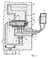
- Figs. 1 - 2 illustrate an assembly of the invention.
- Reference numeral 1 is used to generally designate a filling device.
- the filling device 1 includes a filling head 2, which can be inserted in an attachment point 4 included in an evaporator 3.
- the attachment point 4 can be provided e.g. in the form of a socket, which is the case in the illustrated embodiment.
- the filling device 1 and the evaporator 3 are provided with conduits 5a, 5b and 6a, 6b for carrying an anesthetic from a transport container into a liquid tank included in the evaporator and for delivering a substituting gas from the liquid tank of the evaporator into the transport container.
- an anesthetic transport container 15 and an avaporator liquid tank 16 are only shown in principle in fig. 1.
- these features represent totally conventional technology and, thus, such features are not described in further detail in this context.
- the exemplary embodiment shown in the figures further comprises a clamping implement 7 for tightening the filling head against a wall of the socket serving as the attachment point 4 for the evaporator 3.
- Reference numerals 8 and 9 are used to generally designate valve elements, which are only adapted to open when the filling head 2 is in a position tightened against the wall of the evaporator attachment point 4 and hence to only allow a flow of anesthetic into the liquid tank of an evaporator and a flow of substituting gas into the anesthetic transport container when the filling head 2 is in a position tightened against the wall of the attachment point 4.
- the assembly according to the illustrated example comprises a hydraulic container 10, which is fitted with a first piston element 11 for the regulation of pressure existing within the hydraulic container 10, a second piston element 12 connected to the filling-head tightening implement 7, and a third piston element 13 connected to the valve elements 8, 9 which control the flow of anesthetic and substituting gas.
- the second piston element 12 Upon increasing the pressure in the hydraulic container 10, the second piston element 12 is adapted to tighten the filling head 2 against the wall of the evaporator attachment point 4 before the third piston element 13 commences, as a result of the increase of pressure in the hydraulic container, the process of opening the bvalve elements 8, 9 for allowing the flow of anesthetic and substituting gas and, respectively, upon decreasing the pressure in the hydraulic container 10, the third piston element 13 is adapted to close the valve elements 8, 9 before the second piston element 12 commences the process of loosening the tightening of the filling head 2 from a position compressed against the wall of the attachment point 4. It should be noted that the third piston element can also be adapted to apply only to the liquid-conduit valve element 9.
- Fig. 1 depicts the condition, wherein the filling head 2 is tightened against a wall of the attachment point 4.
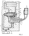
- fig. 2 depicts the condition, wherein the filling of an evaporator is completed.
- the second and third piston element 12, 13 can be preferably designed as spring-loaded elements in such a manner that a spring 12a included in the second valve element 12 is adapted to develop a lesser force than a spring 13a included in the third valve element 13.
- the above-described selection of springs can be used to accomplish in a preferred manner said tightening of the filling head and opening of the valve elements occurring in a proper sequence and, respectively, closing of the valve elements and release of the filling-head tightening. Operation of the assembly will be described in more detail as follows.
- the exemplary solution depicted in the figures is based on a liquid- or fluid-containing hydraulic container 10, which is fitted with three separate hydraulic pistons, piston elements 11, 12, 13.
- One piston 11 is linked to an actuator 11a, capable of operating the first piston element 11 and thus of regulating pressure existing in the container 10.
- the second piston element 12 is connected to a spring-returnable tightener for the filling head 2.
- the third piston element 13 is connected to a likewise spring-returnable filling valve 14, which is provided with the previously mentioned valve elements 8, 9.
- the tightening- or clamping-piston spring 12a is dimensioned to be lighter than the valve-piston spring 13a.
- the clamping piston 12 tightens the filling head 2 against the wall of the attachment point 4 prior to opening of the filling valve, i.e. valve elements 8, 9.
- the clamping piston does not necessarily require a spring at all provided that the pistons have kinetic frictions which are sufficiently low for returning the clamping piston by means of hydraulic suction.
- the opening of the filling valve 14, i.e. valve elements 8, 9, does not occur until the movement of the clamping piston stops as it comes into contact with the filling head 2 immobilized in the attachment point 4 of the evaporator.
- a result of the dimensioning is also an automatic closure of the filling valve 14 if the filling head 2 is disengaged while the valve elements 8, 9 are open and the clamping piston is able to freely advance deeper into the socket serving as the attachment point 4.
- the filling valve 14 does not open at all unless the filling head 2 is in its stationary position in the evaporator attachment point 4 when supplying pressure into the hydraulic system with the assistance of the actuator 11a, the clamping piston 12 pressing unimpededly into the socket serving as the filling-device attachment point 4.
- the dimensioning of pistons and the displacements thereof must be effected by taking into consideration the volume changes of the hydraulic container 10 required for each piston.
- the volume change created by the filling-head 2 clamping piston, i.e. the second piston element 12, between the extreme points of a displacement is at least equal to the maximum change produced by the pressure regulation piston, i.e. the first piston element 11.
- the reason for this is that, if the filling head 2 is not immobilized in its position when the pressure regulation piston 11 is operated through the action of the actuator 11a, the entire volume change must be concentrated on the clamping piston 12 for maintaining the closed condition of the filling-valve piston, i.e.
- the volume change produced by the filling-valve piston 13 must be lesser than that created by the pressure regulation piston 11, subtracted by that volume change of the clamping piston 12, which is maximally required for tightening the filling head 2 as it is immobilized in its position. The reason for this is that the available volume change is capable of both tightening the filling head 2 and still opening the filling valve 14.
- the volume change produced by the pressure regulation piston is determdined from the foregoing.
- the filling head 2 is fitted to the attachment point 4 included in an avaporator.
- the second piston element 12 begins to inch upwards in the situation shown in the figures and presses the filling head 2 against a wall of the attachment point 4, in other words, to th position shown in fig. 1. After the filling head 2 has tightened itself in the position shown in fig.
- the third piston element 13 begins to inch to the right in the situation shown in the figures and carries at the same time the filling valve 14 to the right, whereby the valve elements 8, 9 open and allow the flow of an anesthetic liquid and a substituting gas, as described above, from a transport container 15 into an evaporator liquid tank 16 and, respectively, from the liquid tank 16 into the transport container 15.
- One preferred embodiment for liquid-flow and substituting-gas flow valves i.e. the valve elements 8, 9, is to include the same in the elongated filling valve 14 sequentially along a common axis to extend, for example, in the direction of the filling-head attachment point 4 included in an evaporator in the immediate vicinity of flow conduits.
- the volume from the valve closing point to the filling head 2 is as small as possible.
- the invention relates essentially to an arrangement associated with the above-mentioned valves. Said arrangement will be described in more detail hereinbelow.
- the gas-conduit valve element 8 In terms of the opening sequence of the valve elements, it is essential that the gas-conduit valve element 8 not open prior to the liquid-conduit valve element 9. If this should happen, it might lead to the congestion of the gas conduit by the anesthetic liquid to preclude the filling.
- the liquid-conduit valve element 9 opens first, the liquid shall flow thereby towards the evaporator liquid tank 16 so as to induce, by means of a liquid column, an overpressure in the evaporator and an underpressure in the gas conduit. The pressure difference starts a powerful liquid flow as soon as the gas-conduit valve element 8 opens.
- the double packing is provided in order to preclude the mixing of hydraulic fluid with anesthetic liquid in case of damaged packing.
- a space between the packings 17, 18 can be preferably provided with a ventilation opening wherethrough, in case of a possible packing leak, the leak shall escape out and mixing is avoided.
- valve elements included in gas and liquid conduits are modified relative to the prior art solutions in such a manner that, as the conduits between the transport container 15 and the evaporator liquid tank 16 are closed, i.e. as the valve elements 8, 9 are shut off, the gas conduit 6a of a filling device closer to the transport container 15 and the corresponding liquid conduit 5a are connected to each other.
- the conduits 5a, 6a refer also to conduits included in the filling head 2.
- the conduits 5a, 6a are adapted to be connected to each other in the filling valve 14.
- conduits 5a, 6a can also be connected to each other not just in the filling valve, an example of this being a connection effected in the filling head in the vicinity of the valve elements 8, 9.
- the connection of the conduits 5a, 6a is preferably effected as near the valve elements 8, 9 as possible, since the evacuation shall then occur as quickly and completely as possible.
- Fig. 2 depicts a situation, wherein the filling of the liquid tank 16 is completed but the filling head has not yet been released from compression. In this situation, the conduits between transport container 15 and the evaporator liquid tank 16 are closed and the gas conduit 6a and the liquid conduit 5a are in communication with each other in the filling valve 14, as pointed out above.
- Fig. 1 depicts a situation, wherein the filling of the liquid tank 16 is completed but the filling head has not yet been released from compression. In this situation, the conduits between transport container 15 and the evaporator liquid tank 16 are closed and the gas conduit 6a and the liquid conduit 5a are in communication with each other
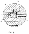
- FIG. 3 illustrates in an enlarged scale as to how the gas and liquid conduits are connected to each other inside the filling head in the example shown in figs. 1 and 2.
- Fig. 3 includes an arrow K to indicate a conduit connecting the gas and liquid conduit.
- Fig. 2 includes a circle to indicate a detail depicted in fig. 3.
- a cut-off element 20 is adapted to open between the conduits for allowing the liquid to flow back into the transport container.
- the cut-off element 20 is in an open position in fig. 3.
- the communication between the conduits 5a, 6a is closed whenever the cut-off element 20 squeezes against a packing 21 shown in fig. 3.
- the filling valves develop no vacuum since, as the liquid flows along one conduit towards the transport container, a substituting gas is allowed to flow from the transport container towards the filling valve.
- Fig. 2 includes arrows to indicate the flow of liquid and substituting gas in this situation.
Landscapes
- Health & Medical Sciences (AREA)
- Anesthesiology (AREA)
- Emergency Medicine (AREA)
- Pulmonology (AREA)
- Engineering & Computer Science (AREA)
- Biomedical Technology (AREA)
- Heart & Thoracic Surgery (AREA)
- Hematology (AREA)
- Life Sciences & Earth Sciences (AREA)
- Animal Behavior & Ethology (AREA)
- General Health & Medical Sciences (AREA)
- Public Health (AREA)
- Veterinary Medicine (AREA)
- Filling Or Discharging Of Gas Storage Vessels (AREA)
Applications Claiming Priority (2)
| Application Number | Priority Date | Filing Date | Title |
|---|---|---|---|
| FI956305 | 1995-12-28 | ||
| FI956305A FI100008B (fi) | 1995-12-28 | 1995-12-28 | Menetelmä ja sovitelma anestesiahöyrystimen täyttöä varten |
Publications (3)
| Publication Number | Publication Date |
|---|---|
| EP0781568A2 true EP0781568A2 (de) | 1997-07-02 |
| EP0781568A3 EP0781568A3 (de) | 1997-12-29 |
| EP0781568B1 EP0781568B1 (de) | 2001-08-22 |
Family
ID=8544619
Family Applications (1)
| Application Number | Title | Priority Date | Filing Date |
|---|---|---|---|
| EP96309484A Expired - Lifetime EP0781568B1 (de) | 1995-12-28 | 1996-12-24 | Verfahren und Vorrichtung zum Füllen eines Narkosemittelverdunsters |
Country Status (4)
| Country | Link |
|---|---|
| US (1) | US5819814A (de) |
| EP (1) | EP0781568B1 (de) |
| DE (1) | DE69614656D1 (de) |
| FI (1) | FI100008B (de) |
Families Citing this family (1)
| Publication number | Priority date | Publication date | Assignee | Title |
|---|---|---|---|---|
| WO2021134369A1 (zh) * | 2019-12-30 | 2021-07-08 | 深圳迈瑞生物医疗电子股份有限公司 | 麻醉机及其麻醉蒸发器 |
Citations (4)
| Publication number | Priority date | Publication date | Assignee | Title |
|---|---|---|---|---|
| EP0455433A1 (de) | 1990-05-01 | 1991-11-06 | The BOC Group plc | Flüssigkeitsabgabesystem |
| DE4106756A1 (de) | 1991-03-01 | 1992-09-03 | Draegerwerk Ag | Sicherheitsfuellvorrichtung mit selbstschliessendem absperrventil |
| FI923196A7 (fi) | 1992-07-10 | 1994-01-11 | Instrumentarium Oy | Kytkentälaitteisto ja menetelmä astian kytkemiseksi kytkentälaitteistoon ja sitä kautta nestesäiliöön |
| FI96384B (fi) | 1994-10-18 | 1996-03-15 | Instrumentarium Oy | Sovitelma anestesiahöyrystimen täyttöä varten |
Family Cites Families (5)
| Publication number | Priority date | Publication date | Assignee | Title |
|---|---|---|---|---|
| GB1193241A (en) * | 1968-01-05 | 1970-05-28 | Cyprane Ltd | Improvements in or relating to Volatile Anaesthetic Vaporising apparatus and a Filling System therefor |
| US4883049A (en) * | 1985-06-13 | 1989-11-28 | Southmedic Incorporated | Apparatus for use in refilling an anesthetic vaporizer |
| DE3523948A1 (de) * | 1985-07-04 | 1987-01-08 | Draegerwerk Ag | Vorrichtung zur versorgung von narkosemittelabgabeeinrichtungen |
| SE464560B (sv) * | 1990-03-30 | 1991-05-13 | Siemens Elema Ab | Anordning foer paafyllning och avtappning av anestesimedel |
| CA2110851C (en) * | 1993-12-07 | 2003-04-01 | Technimeca Medic (2002) Inc. | Device for preventing gas-lock during the transfer of a liquid in a closed system, an arrangement containing the same and a method of use |
-
1995
- 1995-12-28 FI FI956305A patent/FI100008B/fi not_active IP Right Cessation
-
1996
- 1996-12-24 EP EP96309484A patent/EP0781568B1/de not_active Expired - Lifetime
- 1996-12-24 DE DE69614656T patent/DE69614656D1/de not_active Expired - Lifetime
- 1996-12-27 US US08/773,432 patent/US5819814A/en not_active Expired - Fee Related
Patent Citations (4)
| Publication number | Priority date | Publication date | Assignee | Title |
|---|---|---|---|---|
| EP0455433A1 (de) | 1990-05-01 | 1991-11-06 | The BOC Group plc | Flüssigkeitsabgabesystem |
| DE4106756A1 (de) | 1991-03-01 | 1992-09-03 | Draegerwerk Ag | Sicherheitsfuellvorrichtung mit selbstschliessendem absperrventil |
| FI923196A7 (fi) | 1992-07-10 | 1994-01-11 | Instrumentarium Oy | Kytkentälaitteisto ja menetelmä astian kytkemiseksi kytkentälaitteistoon ja sitä kautta nestesäiliöön |
| FI96384B (fi) | 1994-10-18 | 1996-03-15 | Instrumentarium Oy | Sovitelma anestesiahöyrystimen täyttöä varten |
Also Published As
| Publication number | Publication date |
|---|---|
| DE69614656D1 (de) | 2001-09-27 |
| US5819814A (en) | 1998-10-13 |
| FI956305A0 (fi) | 1995-12-28 |
| EP0781568A3 (de) | 1997-12-29 |
| FI956305A7 (fi) | 1997-06-29 |
| EP0781568B1 (de) | 2001-08-22 |
| FI100008B (fi) | 1997-08-15 |
Similar Documents
| Publication | Publication Date | Title |
|---|---|---|
| US5585045A (en) | Arrangement for filling an anaesthetic vaporiser | |
| US6435494B2 (en) | Clamp apparatus | |
| EP0220193B1 (de) | Füllventil | |
| KR20020042638A (ko) | 서지 방지 장치 | |
| EP1735106A2 (de) | Flüssigkeitsabgabeventil und -verfahren mit verbesserter hublängenkalibrierung und verbesserten fluidarmaturen | |
| AU4841000A (en) | Hydraulic control apparatus for a hospital bed | |
| DE50009213D1 (de) | Ventil zum steuern von flüssigkeiten | |
| CN1847707B (zh) | 带有枢转致动器组件的配给器 | |
| EP0781568B1 (de) | Verfahren und Vorrichtung zum Füllen eines Narkosemittelverdunsters | |
| JP4191279B2 (ja) | 麻酔用蒸発装置 | |
| BR0207621A (pt) | Aparelho para lançar um ou mais tubos em uma linha de fluxo | |
| JP4903197B2 (ja) | 迅速連結器用作動装置 | |
| EP1331199A3 (de) | Steuervorrichtung, insbesondere für den Einsatz bei hydraulisch arbeitenden Hubeinrichtungen | |
| CN114776810A (zh) | 一种管道在线多重安全密封里衬取样阀 | |
| US4611618A (en) | Frangible fittings | |
| EP1652765A3 (de) | Ventilanordnung kontrolliert durch Druckänderung | |
| DE60127448T2 (de) | Servogesteuertes sicherheitsventil für behälter für toxische fluide | |
| US6769450B2 (en) | Valve system | |
| CN113775587B (zh) | 一种液压远程控制比例流量调节阀 | |
| JPS59500280A (ja) | 取囲んだ保護導管又はホ−スをもつた圧力導管又はホ−ス用の導管−破損弁 | |
| US3106222A (en) | Valved coupling | |
| US4424827A (en) | Device for detachably coupling the orifice of a branchline to a line carrying a pressure medium | |
| CN223854905U (zh) | 一种便于安装的三通阀 | |
| JP3455491B2 (ja) | 負圧リリーフ弁 | |
| GB9001373D0 (en) | Fluid pressure modulator valves |
Legal Events
| Date | Code | Title | Description |
|---|---|---|---|
| PUAI | Public reference made under article 153(3) epc to a published international application that has entered the european phase |
Free format text: ORIGINAL CODE: 0009012 |
|
| AK | Designated contracting states |
Kind code of ref document: A2 Designated state(s): DE FR GB IT NL SE |
|
| PUAL | Search report despatched |
Free format text: ORIGINAL CODE: 0009013 |
|
| AK | Designated contracting states |
Kind code of ref document: A3 Designated state(s): DE FR GB IT NL SE |
|
| 17P | Request for examination filed |
Effective date: 19980501 |
|
| GRAG | Despatch of communication of intention to grant |
Free format text: ORIGINAL CODE: EPIDOS AGRA |
|
| GRAG | Despatch of communication of intention to grant |
Free format text: ORIGINAL CODE: EPIDOS AGRA |
|
| GRAH | Despatch of communication of intention to grant a patent |
Free format text: ORIGINAL CODE: EPIDOS IGRA |
|
| 17Q | First examination report despatched |
Effective date: 20010111 |
|
| RAP1 | Party data changed (applicant data changed or rights of an application transferred) |
Owner name: INSTRUMENTARIUM CORPORATION |
|
| GRAH | Despatch of communication of intention to grant a patent |
Free format text: ORIGINAL CODE: EPIDOS IGRA |
|
| GRAA | (expected) grant |
Free format text: ORIGINAL CODE: 0009210 |
|
| AK | Designated contracting states |
Kind code of ref document: B1 Designated state(s): DE FR GB IT NL SE |
|
| PG25 | Lapsed in a contracting state [announced via postgrant information from national office to epo] |
Ref country code: NL Free format text: LAPSE BECAUSE OF FAILURE TO SUBMIT A TRANSLATION OF THE DESCRIPTION OR TO PAY THE FEE WITHIN THE PRESCRIBED TIME-LIMIT Effective date: 20010822 Ref country code: IT Free format text: LAPSE BECAUSE OF FAILURE TO SUBMIT A TRANSLATION OF THE DESCRIPTION OR TO PAY THE FEE WITHIN THE PRESCRIBED TIME-LIMIT;WARNING: LAPSES OF ITALIAN PATENTS WITH EFFECTIVE DATE BEFORE 2007 MAY HAVE OCCURRED AT ANY TIME BEFORE 2007. THE CORRECT EFFECTIVE DATE MAY BE DIFFERENT FROM THE ONE RECORDED. Effective date: 20010822 Ref country code: FR Free format text: LAPSE BECAUSE OF FAILURE TO SUBMIT A TRANSLATION OF THE DESCRIPTION OR TO PAY THE FEE WITHIN THE PRESCRIBED TIME-LIMIT Effective date: 20010822 |
|
| RIN1 | Information on inventor provided before grant (corrected) |
Inventor name: HEINONEN, ERKKI, MR. Inventor name: KANKKUNEN, JUKKA, MR. |
|
| REF | Corresponds to: |
Ref document number: 69614656 Country of ref document: DE Date of ref document: 20010927 |
|
| PG25 | Lapsed in a contracting state [announced via postgrant information from national office to epo] |
Ref country code: SE Free format text: LAPSE BECAUSE OF FAILURE TO SUBMIT A TRANSLATION OF THE DESCRIPTION OR TO PAY THE FEE WITHIN THE PRESCRIBED TIME-LIMIT Effective date: 20011122 |
|
| PG25 | Lapsed in a contracting state [announced via postgrant information from national office to epo] |
Ref country code: DE Free format text: LAPSE BECAUSE OF FAILURE TO SUBMIT A TRANSLATION OF THE DESCRIPTION OR TO PAY THE FEE WITHIN THE PRESCRIBED TIME-LIMIT Effective date: 20011123 |
|
| PGFP | Annual fee paid to national office [announced via postgrant information from national office to epo] |
Ref country code: SE Payment date: 20011203 Year of fee payment: 6 |
|
| REG | Reference to a national code |
Ref country code: GB Ref legal event code: IF02 |
|
| EN | Fr: translation not filed | ||
| NLV1 | Nl: lapsed or annulled due to failure to fulfill the requirements of art. 29p and 29m of the patents act | ||
| PLBE | No opposition filed within time limit |
Free format text: ORIGINAL CODE: 0009261 |
|
| STAA | Information on the status of an ep patent application or granted ep patent |
Free format text: STATUS: NO OPPOSITION FILED WITHIN TIME LIMIT |
|
| 26N | No opposition filed | ||
| PGFP | Annual fee paid to national office [announced via postgrant information from national office to epo] |
Ref country code: GB Payment date: 20081229 Year of fee payment: 13 |
|
| GBPC | Gb: european patent ceased through non-payment of renewal fee |
Effective date: 20091224 |
|
| PG25 | Lapsed in a contracting state [announced via postgrant information from national office to epo] |
Ref country code: GB Free format text: LAPSE BECAUSE OF NON-PAYMENT OF DUE FEES Effective date: 20091224 |