EP0780780B1 - Gerät zur Bildverarbeitung von Fingerabdrücken - Google Patents
Gerät zur Bildverarbeitung von Fingerabdrücken Download PDFInfo
- Publication number
- EP0780780B1 EP0780780B1 EP96120179A EP96120179A EP0780780B1 EP 0780780 B1 EP0780780 B1 EP 0780780B1 EP 96120179 A EP96120179 A EP 96120179A EP 96120179 A EP96120179 A EP 96120179A EP 0780780 B1 EP0780780 B1 EP 0780780B1
- Authority
- EP
- European Patent Office
- Prior art keywords
- ridge line
- line candidate
- dimensional
- image
- candidate image
- Prior art date
- Legal status (The legal status is an assumption and is not a legal conclusion. Google has not performed a legal analysis and makes no representation as to the accuracy of the status listed.)
- Expired - Lifetime
Links
Images


Classifications
-
- G—PHYSICS
- G06—COMPUTING; CALCULATING OR COUNTING
- G06V—IMAGE OR VIDEO RECOGNITION OR UNDERSTANDING
- G06V40/00—Recognition of biometric, human-related or animal-related patterns in image or video data
- G06V40/10—Human or animal bodies, e.g. vehicle occupants or pedestrians; Body parts, e.g. hands
- G06V40/12—Fingerprints or palmprints
- G06V40/1347—Preprocessing; Feature extraction
-
- G—PHYSICS
- G06—COMPUTING; CALCULATING OR COUNTING
- G06F—ELECTRIC DIGITAL DATA PROCESSING
- G06F18/00—Pattern recognition
Definitions
- the present invention relates to an image processing apparatus for identifying fingerprints and palmprints, in particular, an image processing apparatus for acquiring ridge line images from skin pattern images.
- a technology disclosed as for example Japanese Patent Examined Publication No. 5-746 titled "Fingerprint Image Coding Method" is known.
- the fingerprint image coding method a fingerprint image is divided into small regions. For each small region, two-dimensional Fourier transformation is performed. With information of each transformed plane, features of the fingerprint image are extracted.
- Such wrinkles have relatively good connectivity of features such as directions and pitches with adjacent regions, when components of wrinkles are selected, the entire energy may decrease. Where wrinkles are clearly present, the reliability for extracting features of ridge lines occasionally increases. Thus, when an image including such wrinkles is smoothed, the adjacent regions matched to the wrinkles thereof are also smoothed. Consequently, the wrinkles may be emphasized. In addition, it is difficult to define the energy function E that allows the above-described problem to be solved.
- the relaxation method is used as a technique for smoothing information with respect to directions extracted for individual local regions. Even in this technique, wrinkles that frequently extend and go side by side at equal pitches on a palmprint are smoothed such as matched to the wrinkle and emphasized.
- An object of the present invention is to provide an image processing apparatus for correctly extracting ridge lines of fingerprints from an image that includes wrinkles that extend at the same pitches of the ridge lines of fingerprints and each go side by side with.
- the present invention is a fingerprint/palmprint image processing apparatus for extracting ridge lines from an input fingerprint/ palmprint image, comprising a local information extracting means for dividing the fingerprint/palmprint image into two-dimensional local regions and extracting in each of the two-dimensional local regions a plurality of ridge line candidate images that represent ridge lines from each of the two-dimensional local regions, a first ridge line candidate image selecting means for evaluating the likelihood that each ridge line candidate image represents a ridge line, and selecting one first ridge line candidate image that represents a ridge line candidate image with the maximum likelihood of a ridge line from ridge line candidate images in each of the two-dimensional local regions, a connectivity evaluating means for evaluating the connectivity between two adjacent ridge line candidates in adjacent two-dimensional local regions, a clustering means for clustering two-dimensional local regions that have high connectivity of first ridge line candidate images corresponding to the determined result of the connectivity evaluating means and generating a local region group, a cluster evaluating means for evaluating the likelihood that the first ridge line candidate images
- the present invention has an optimum ridge line candidate image selecting means for evaluating the connectivity of the first ridge line candidate image in each of the two-dimensional local regions included in the initial local region group and a plurality of ridge line candidate images in each of the two-dimensional local regions that are not included in the initial local region group, selecting one ridge line candidate image with the highest connectivity between ridge line candidates in each of the two-dimensional local regions that are not included in the initial local region group as an optimum ridge line candidate image, and selecting a first ridge line candidate image in each of the two-dimensional local regions that are included in the initial local region group as an optimum ridge line candidate image, wherein the ridge line image restoring means outputs the optimum ridge line candidate image as a ridge line image.
- the present invention has a control means for supplying the optimum ridge line candidate image as a first ridge line candidate image to the connectivity evaluating means and the cluster evaluating means and controlling cyclical executions of processes of the connectivity evaluating means, the clustering means, the cluster evaluating means, and the optimum ridge line candidate image selecting means.
- the local information extracting means performs two-dimensional Fourier transformation for each of the two-dimensional local regions, extracts a plurality of peaks corresponding to two-dimensional sine waves on the resultant Fourier transformation plane in the order of the largest amplitude or the largest energy in the vicinity of peaks, treats two-dimensional sine waves corresponding to the peaks as ridge line candidate images.
- the first ridge line candidate image selecting means determines a ridge line candidate image with the largest amplitude in each of the two-dimensional local region as the first ridge line candidate image.
- connectivity evaluating means evaluates the connectivity of the first ridge line candidate images with at least one, or more, or all of:
- the cluster evaluating means evaluates a grade of the likelihood of a ridge line in each of the local region groups corresponding to at least one of:
- the optimum ridge line candidate image selecting means successively selects the optimum candidate images from two-dimensional local regions that are not included in the initial local region groups in the order of the smallest distance with two-dimensional local regions that are included in the initial local region groups.
- the optimum ridge line candidate image selecting means When selecting an optimum candidate image, the optimum ridge line candidate image selecting means,
- a plurality of candidate images that represent ridge lines are extracted from each local region.
- An candidate image with the most likelihood of a ridge line is selected from the candidate images for each local region.
- the extracted candidate images are referred to as first ridge line candidate images.
- a local region of which a first ridge line candidate image represents a true ridge line is found.
- a group of such local regions is referred to as initial local region group. Only ridge lines in local regions included in the initial local region group are restored with first ridge line candidate images in the local regions.
- first ridge line candidate images in an initial local region group correctly represent ridge lines
- images that represent ridge lines are selected from ridge line candidate images in local regions not included in the initial local region group.
- images that represent ridge lines are successively selected from local regions most close to the initial local region group.
- the connectivity of each first ridge line candidate image of each local region included in the initial local region group and each candidate image in each local region that has formerly been selected is evaluated. An candidate image with the highest connectivity is selected.
- each first ridge line candidate image in the local region represents a ridge line.
- each ridge line candidate image selected in the above-described method represents a ridge line.
- a portion represents a ridge line
- other portions of the ridge line is determined corresponding to the connectivity with the detected portion. Since there is no connectivity between a wrinkle and a ridge line, with such a technique, even if a wrinkle and a ridge line overlay, a ridge line candidate image that represents a ridge line rather than a ridge line candidate image that a wrinkle can be selected.
- ridge line candidate images that have formerly been selected may be verified.
- the above-described process is performed once. Thereafter, the connectivity of ridge line candidate images that have been selected are evaluated again. Local regions with high connectively are clustered into one group. The likelihood of clustered ridge lines is determined so as to obtain an initial local region group. Ridge line candidate images are selected from each of local regions that are not included in the initial local region group. The connectivity of the selected ridge line candidate images are determined and then the above-described process is performed. By repeating such a process several times, with ridge line candidate images that have been finally obtained, ridge line images are restored.
- Ridge line candidate images that have been selected include more ridge line images than first ridge line candidate images that have been selected first time.
- the area of ridge line images becomes larger than that of the ridge line candidate images that have been selected first time.
- it is high probability that ridge line candidate images selected from the local region block probably represent ridge lines.
- portions selected corresponding to the ridge line candidate images tend to accurately represent ridge lines. Consequently, ridge lines can be restored with higher reliability.
- Ridge lines are locally well approximated with two-dimensional sine waves.
- a ridge line in each local region is modeled with a two-dimensional sine wave.
- several sine waves that well approximate the local regions are extracted.
- amplitudes of a wrinkle and a ridge line vary image by image.
- characteristics of wrinkles are locally similar to characteristics of ridge lines, the wrinkles and ridge lines have the maximum amplitudes at the same frequency.
- a peak with large amplitude tends to individually represent a ridge line. Consequently, when a sine wave corresponding to a peak with the maximum amplitude is selected, a ridge line candidate image that represents a ridge line can be effectively selected.
- the feature amount (5) is conducted from the following theory.
- a first ridge line candidate image in each local region is one of the two wrinkles that intersect.
- the size of the local region group obtained by the connectivity evaluating process does not become large. In other words, many small local region groups are formed.
- the ridge line becomes a first ridge line candidate image.
- the size of the local region group becomes large.
- candidate images that represent wrinkles tend to become a small local region group.
- candidate images that represent ridge lines tend to become a large local region group.
- the connectivity of a wrinkle portion between local regions is slightly lower than that of a ridge line therebetween.
- Ridge lines are densely present on the skin.
- the spacial variations of the directions and pitches of the ridge lines are gradual.
- the connectivity of adjacent wrinkles is lower than that of ridge lines.
- the feature amount (7) represents the amount of the component of a first ridge line candidate image contained in an image in each local region.
- the component other than a first ridge line candidate image is contained large. In such a local region, a wrinkle is included. Alternatively, an image of ridge lines is broken or unclear. Thus, the tendency of which a first ridge line candidate image is a ridge line is low.
- a local region includes a wrinkle, it must be an candidate with large energy.
- ridge lines are present where wrinkles are present.
- two or three candidate with large energy are present.
- a ridge line candidate image other than a first ridge line candidate image has only small energy.
- the value of which the sum of the energy of first ridge line candidate images in a local region group to be determined is divided by the sum of the energy of ridge line candidate images other than the first ridge line candidate images is large, the tendency of which a wrinkle is not present becomes high.
- the tendency of which a first ridge candidate image represents a ridge line becomes high.
- a local region group that is a group of local regions of which a first ridge line candidate image represents a ridge line is obtained with the above-described feature amounts.
- a local region of which the cluster evaluating means has determined that a first ridge line candidate image represents a ridge line is referred to as an initial local region.
- An optimum ridge line candidate image is successively selected from local regions adjacent to an initial local region.
- the selecting manner in each of local regions is performed in the following manner.
- the connectivity of the directions, pitches, phases, and pixel values of each ridge line candidate image in a local region to be selected, and each first ridge line candidate image in the initial local region in the vicinity of the local region is determined. And the optimum ridge line candidate image in each local region that has formerly been selected is determined.
- a ridge line candidate image of which the difference of the directions, pitches, phases, and pixel values of the adjacent portions of a first ridge line candidate image in the initial local region and a optimum ridge line candidate image in the local region that has been selected become small and where the first ridge line candidate image and the ridge line candidate image are disposed adjacently or in the vicinity tends probably to represent a ridge line.
- ridge line candidate images that represent ridge lines can be accurately selected.
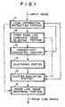
- Fig. 1 shows a structure of a fingerprint/palmprint image processing apparatus according to the present invention.
- the fingerprint/palmprint image processing apparatus comprises a local information extracting portion 11, a first ridge line candidate image selecting portion 12, a connectivity evaluating portion 13, a clustering portion 14, a cluster evaluating portion 15, and a ridge line image restoring portion 16.
- the local information extracting portion 11 divides an input image into two-dimensional local regions and extracts a plurality of candidate images that represent ridge lines in the local regions (the extracted candidate images are referred to as ridge line candidate images).
- the first ridge line candidate image selecting portion 12 evaluates grades of the likelihood of a ridge line for each of the ridge line candidate images extracted in each local region and selects one first ridge line candidate image that has the maximum likelihood of a ridge line for each local region.
- the connectivity evaluating portion 13 evaluates the connectivity of first ridge line candidate images between each local region.
- the clustering portion 14 generates a local region group that is a group of local regions with high connectivity of first ridge line candidate images evaluated by the connectivity evaluating portion 13.
- the cluster evaluating portion 15 evaluates the likelihood of a ridge line for first ridge line candidate image in each local region included in the local region group generated by the clustering portion 14 and determines an initial local region group that is a local region group with high likelihood of a ridge line.
- the ridge line image restoring portion 16 outputs as a ridge line image a first ridge line candidate image in each local region included in the initial local region group.
- the local information extracting portion 11 divides a digital image of a skin pattern into local regions.
- the skin pattern such as a fingerprint or a palmprint is photographed by an image input unit such as a scanner or a TV camera.
- an image input unit such as a scanner or a TV camera.
- an input image is photographed with a resolution of 512 x 512 pixels at 20 dots/mm and each local region has 8 x 8 pixels as shown in Fig. 2.
- an input image may be processed in the case of other resolutions, other image sizes, and local region sizes
- each local image with a predetermined width at the center of each local region is Fourier-transformed.
- This process is exemplified with a local image of 64 x 64 pixels as shown in Fig. 3.
- a pixel that is disposed at the 32-nd column position and at the 32-nd row position counted from the upper left corner of each local image is defined as the origin.
- the left and right directions are denoted by x.
- the right direction is defined as the positive direction.
- the upper and lower directions are denoted by y.
- the lower direction is defined as the positive direction.
- the DC component of an image of which w(x, y) is multiplied by the local image g(x, y) is subtracted from the original image.
- the DC component can be expressed by Formula 3.
- the resultant image is multiplied by w(x, y).
- the resultant image is expressed by Formula 4.
- in the region F( ⁇ , ⁇ ) of which f(x, y) has been Fourier-transformed are selected in the order of the largest value of
- the region F( ⁇ , ⁇ ) can be expressed by Formula 5. [Formula 5] ⁇ , ⁇ )
- the power in the vicinity of a peak can be expressed by Formula 12.
- the local information extracting portion 11 supplies values of parameters (expressed by Formula 16) for each local region to the first ridge line candidate image selecting portion 12, the connectivity evaluating portion 13, the cluster evaluating portion 15, and the ridge line image restoring portion 16.
- the first ridge line candidate image selecting portion 12 selects one sine wave that has the maximum likelihood of a ridge line for each local region corresponding to information of sine waves of ridge line candidate images.
- the connectivity with adjacent local regions is not considered, but information of considered local regions is considered.
- Such a sine wave is referred to as a first ridge line candidate image.
- the amplitude of a sine wave can be used.
- a sine wave with the maximum amplitude is selected as a sine wave with the maximum likelihood of a ridge line.
- the first ridge line candidate image selecting portion 12 supplies a two-dimensional array (expressed by Formula 17) that represents ridge line candidate images for each local region extracted by the local information extracting portion 11 to the connectivity evaluating portion 13 and the cluster evaluating portion 15.
- the connectivity evaluating portion 13 evaluates ridge line candidate images for each local region corresponding to Formula 17 (namely, the connectivity of individual information of first ridge line candidate images between each adjacent local region).
- Formula 17 the connectivity of individual information of first ridge line candidate images between each adjacent local region.
- pixels represented by lattice points shown in Fig. 5 are evaluated for each region.
- a local region I ij is restored with a first ridge line candidate image
- the values of pixels that extend to a particular mesh point and the values of pixels of adjacent local regions are compared and the sum J 1 of each difference is obtained.
- the difference can be expressed by Formula 18.
- the connectivity of directions is evaluated corresponding to the difference of directions of first ridge line candidate images in adjacent local regions.
- the difference of the directions of the first ridge line candidate images can be expressed by Formula 20 with a parameter (expressed by Formula 19) that represents the direction of a sine wave of a first ridge line candidate image in a two-dimensional local region I ij . [Formula 19] d I ij 1
- the connectivity of pitches is evaluated corresponding to the difference of the pitches of sine waves that represent first ridge line candidate images in adjacent local regions.
- the difference of the pitches can be expressed by Formula 22 with the frequency (expressed by Formula 21) of sine waves that represent the first ridge line candidate images in a region I ij . [Formula 21] f (i,j) 1
- the phase of a sine wave is equal to what the minimum distance between the origin of the local coordinate system of each local region and a set of points with the maximum value of a sine wave is multiplied by 2 ⁇ and the frequency of the sine wave.
- those values directly should not be compared, but they should be converted into one of their coordinate systems.
- the coordinate system of the adjacent local region is converted into that of the local region I ij and the difference thereof is obtained.
- Formula 27 By unifying four feature amounts J 1 , J 2 , J 3 , and J 4 , the connectivity of local regions is evaluated. As a method for unifying these feature amounts, Formula 27 can be used.
- the clustering portion 14 clusters local regions that have been determined as connected local regions in the adjacent local regions as the result of the connectivity evaluation by the connectivity evaluating portion 13 and generates a local region group.
- connection failure sides As an evaluated result of the connectivity by the connectivity evaluating portion 13, a local region group that is surrounded by a not-connected side and edge sides of an image as a closed region is extracted. Local regions in the same closed region are extracted as one local region group.
- sides of local regions that has been determined as not-connected sides and edge sides of images are referred to as connection failure sides.
- connection failure sides that are connected are grouped as a connection failure side group. Thereafter, the connection failure side group is categorized as closed regions and open regions. The closed regions are assigned serial numbers. The closed regions each become local region groups.
- label ij represents a two-dimensional array of label numbers of local region groups included in a local region I ij as expressed by Formula 29. The two-dimensional array is supplied to the cluster evaluating portion 15.
- the cluster evaluating portion 15 evaluates the likelihood of a ridge line of a first ridge line candidate image in each local region included in each local region group generated by the clustering portion 14 and determines an initial local region group that is a local region group with high likelihood of a ridge line.
- the number of local regions that structures each local region group is calculated.
- Several local region groups are determined as initial local region groups in the order of the largest number of local regions.
- four local region groups are determined as initial local region groups in the order of the largest number of local regions.
- the ridge line image restoring portion 16 outputs a ridge line candidate image corresponding to a number being stored in the two-dimensional array (Formula 30) supplied by the cluster evaluating portion 15 for each local region I ij .
- the image is calculated and restored corresponding to Formulas 30 and 14 with the parameter group supplied by the local information extracting portion 11. However, when the value of peak ij is 0, since a ridge line is not extracted from the local region, an image is not restored from this region.
- the ridge line image restoring portion 16 outputs the resultant image as the final result.
- a ridge line image is obtained from the input fingerprint/palmprint image.
- Fig. 6 shows the structure of the fingerprint/ palmprint image processing apparatus according to the second embodiment of the present invention.
- a local information extracting portion 11, a first ridge line candidate image selecting portion 12, a connectivity evaluating portion 13, a clustering portion 14, and a cluster evaluating portion 15 of fingerprint/palmprint image processing apparatus according to the second embodiment perform the same processes as those of the apparatus shown in Fig. 1. In other words, the processes of until initial local region groups are determined are the same as those of the fingerprint/palmprint image processing apparatus shown in Fig. 1.
- the cluster evaluating portion 15 supplies a label number of a local region group determined as an initial local region group to an optimum ridge line candidate image selecting portion 17.
- the optimum ridge line candidate image selecting portion 17 selects a ridge line candidate image in each local region that is not included in the initial local region group determined by the cluster evaluating portion 15.
- the optimum ridge line candidate image selecting portion 17 selects local regions adjacent to a local region included in the initial local region group determined by the cluster evaluating portion 15. When there is no more adjacent local region, the optimum ridge line candidate image selecting portion 17 selects local regions adjacent to the local region that has been selected. The optimum ridge line candidate image selecting portion 17 repeats this process until all local regions are selected (see Fig. 7).
- Local regions are selected from adjacent local regions with the connectivity of
- adjacent local regions that are disposed adjacent to at least one of four sides of a particular local region are treated as local regions.
- the apparatus can be structured with another definition of adjacent local regions.
- a ridge line candidate image for which the connectivity is evaluated is a ridge line candidate image with a number of a two-dimensional array (expressed by Formula 30).
- a local region included in the initial local region is a first ridge line candidate image.
- a local region which has been selected at the point is a ridge line candidate image for which the connectivity is evaluated.
- the connectivity of such ridge line candidate images and a plurality of ridge line candidate images in a local region to be selected is evaluated.
- One ridge line candidate image with good connectivity is selected from such ridge line candidate images.
- the connectivity of each ridge line candidate image is evaluated with four feature amounts that will be described in the following.
- the first feature amount is the connectivity of the directions of a local region to be evaluated and four local regions adjacent thereto.
- the second feature amount is the connectivity of pitches of a local region to be evaluated and each of four local regions adjacent thereto.
- the sum of absolute values of the difference of the pitch of each of four adjacent local regions included in the initial local region group or each two-dimensional sine wave that represents a ridge line candidate image corresponding to a number stored in the two-dimensional array (expressed by Formula 30) in each local region that has been selected and the pitch of each ridge line candidate image in each local region to be selected is calculated for all ridge line candidate images in each local region. It is assumed that the sum of the difference of the pitch of a local region to be selected and the pitch of the n-th ridge line candidate image of each local region to be selected is denoted by J2 n .
- the third feature amount is the difference of the direction of a local region to be evaluated and the direction that represents local regions adjacent thereto.
- the direction of a local region (Fig. 7) spaced apart from a local region to be selected by a predetermined length or less or the direction of a local region that has been selected and the direction of a local region that represents these local regions are calculated (see Fig. 8).
- d(bar) the direction of the ridge line candidate image determined as the ridge line of the local region k
- d(bar) can be expressed by Formula 31.
- the fourth feature amount is the difference of the pitch of a local region to be evaluated and the average of pitches of local regions adjacent thereto.
- the average of pitches of local regions that are spaced apart from a local region to be selected by a predetermined length or less and that are included in an initial local region group or that have been selected is calculated.
- the pitch of a sine wave that represents a ridge line candidate image that has been determined as a ridge line in each local region is denoted by ⁇ 1/f (k) ⁇
- N the number of local regions that are disposed within the predetermined distance and whose pitches are averaged (thus, the number of local regions that are included in the initial local region group or that have been selected)
- N the average pitch can be expressed by Formula 33.
- a ridge line candidate image is selected for each local region.
- a ridge line candidate image of which J3 n is minimized is selected from those that satisfy Formula 35.
- Peak ij represents a peak number of the local region I ij .
- the ridge line image restoring portion 16 outputs a ridge line candidate image corresponding to a number stored in the two-dimensional array (expressed by Formula 30) supplied from the optimum ridge line candidate image selecting portion 17 for each local region I ij .
- the ridge line image restoring portion 16 generates an image corresponding to Formula 14 with a parameter group expressed by Formula 37 supplied from the local information extracting portion 11.
- the fingerprint/palmprint image processing apparatus shown in Fig. 6 obtains a ridge line image corresponding to an input fingerprint/palmprint image.
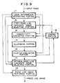
- an optimum ridge line candidate image selecting portion 17 selects an image that represents a ridge line from the ridge line candidate images corresponding to the connectivity of adjacent ridge line candidate images. Thereafter, the third embodiment in the present invention recognizes and determines connectivity of the selected ridge line candidate images so as to extract and correct each local region from which incorrect ridge line candidate images have been selected.
- the other processes of the fingerprint/palmprint image processing apparatus according to the third embodiment are the same as those of the second embodiment shown in Fig. 6.
- output data of a first ridge line candidate image selecting portion 12 is supplied to a control portion 18.
- the control portion 18 receives data from the first ridge line candidate image selecting portion 12, the control portion 12 directly outputs a two-dimensional array (expressed by Formula 17) to a connectivity evaluating portion 13 and a cluster evaluating portion 15.
- the two-dimensional array (expressed by Formula 30) that is output data of the optimum ridge line candidate image selecting portion 17 is supplied to the control portion 18.
- control portion 18 When the control portion 18 receives data from the optimum ridge line candidate image selecting portion 17, the control portion 18 copies the two-dimensional array (expressed by Formula 30) to the two-dimensional array (expressed by Formula 17) and outputs the two-dimensional array (expressed by Formula 17) to the connectivity evaluating portion 13 and the cluster evaluating portion 15.
- the connectivity evaluating portion 13, clustering portion 14, cluster evaluating portion 15, and optimum ridge line candidate image selecting portion 17 perform respective processes.
- control portion 18 determines whether or not the processes should be completed.
- the two-dimensional array (expressed by Formula 30) that is supplied from the optimum ridge line candidate image selecting portion 17 is supplied to the control portion 18 once again.
- the control portion 18 and other portions repeats the same process.
- the control portion 18 has determined that the process should be completed, the optimum ridge line candidate image selecting portion 17 supplies the two-dimensional array (expressed by Formula 30) to the ridge line image restoring portion 16 so as to calculate an image to be restored.
- the determination of whether the process should be completed by the control portion 18 is performed whether or not the number of times of the repeated process becomes a predetermined value or whether or not the number of local regions to be updated becomes smaller than that of an optimum ridge line candidate image that has been selected by a predetermined value.
- the ridge line image restoring portion 16 outputs a ridge line candidate image corresponding to a number stored in the two-dimensional array (expressed by Formula 30) supplied from the optimum ridge line candidate image selecting portion 17 for each local region I ij .
- the ridge line image restoring portion 16 generates and outputs an image corresponding to Formula 14.
- the fingerprint/palmprint image processing apparatus shown in Fig. 9 obtains a ridge image corresponding to an input fingerprint/palmprint image.
- a ridge line image can be accurately extracted from a skin pattern image.
Landscapes
- Engineering & Computer Science (AREA)
- Theoretical Computer Science (AREA)
- Physics & Mathematics (AREA)
- Computer Vision & Pattern Recognition (AREA)
- General Physics & Mathematics (AREA)
- Multimedia (AREA)
- Human Computer Interaction (AREA)
- Bioinformatics & Computational Biology (AREA)
- Evolutionary Computation (AREA)
- Evolutionary Biology (AREA)
- General Engineering & Computer Science (AREA)
- Data Mining & Analysis (AREA)
- Life Sciences & Earth Sciences (AREA)
- Bioinformatics & Cheminformatics (AREA)
- Artificial Intelligence (AREA)
- Collating Specific Patterns (AREA)
- Image Analysis (AREA)
Claims (9)
- Fingerabdruck/Handflächenabdruck-Bildverarbeitungsvorrichtung zur Extraktion von Kammlinien aus einem Eingangs-Fingerabdruck/Handflächenabdruck-Bild, die aufweist:eine Extraktionseinrichtung (11) für lokale Informationen zur Unterteilung des Fingerabdruck/Handflächenabdruck-Bildes in zweidimensionale lokale Bereiche und Extraktion in jedem der zweidimensionalen lokalen Bereiche mehrerer Kammlinienkandidatenbilder, die mögliche Kammlinien aus jedem der zweidimensionalen lokalen Bereiche repräsentieren;eine erste Kammlinienkandidatenbild-Auswahleinrichtung (12) zur Bewertung der Wahrscheinlichkeit, daß jedes Kammlinienkandidatenbild eine Kammlinie repräsentiert, und Auswählen eines ersten Kammlinienkandidatenbildes, das ein Kammlinienkandidatenbild mit der maximalen Wahrscheinlichkeit einer Kammlinie aus Kammlinienkandidatenbildern in jedem der zweidimensionalen lokalen Bereiche repräsentiert;eine Verbindbarkeitsbewertungseinrichtung (13) zur Bewertung der Verbindbarkeit zwischen zwei benachbarten Kammlinienkandidaten in benachbarten zweidimensionalen lokalen Bereichen;eine Gruppierungseinrichtung (14) zur Gruppierung zweidimensionaler lokaler Bereiche, die eine hohe Verbindbarkeit erster Kammlinienkandidatenbilder aufweisen, die dem festgestellten Ergebnis der Verbindbarkeitsbewertungseinrichtung entsprechen, und Erzeugung einer lokalen Bereichsgruppe;eine Gruppenbewertungseinrichtung (15) zur Bewertung der Wahrscheinlichkeit, daß die ersten Kammlinienkandidatenbilder in jedem der zweidimensionalen lokalen Bereiche, die in der lokalen Bereichsgruppe enthalten sind, die durch die Gruppierungseinrichtung erzeugt werden, eine Kammlinie repräsentieren, und Bestimmung einer lokalen Bereichsgruppe, die eine hohe Wahrscheinlichkeit einer Kammlinie aufweist, als eine anfängliche lokale Bereichsgruppe, und eine Kammlinienbildwiederherstellungseinrichtung (16) zur Ausgabe des ersten Kammlinienkandidatenbildes in jedem der lokalen Bereiche, die in der anfänglichen lokalen Bereichsgruppe enthalten sind, als ein Kammlinienbild.
- Fingerabdruck/Handflächenabdruck-Bildverarbeitungsvorrichtung nach Anspruch 1, die ferner aufweist:wobei die Kammlinienbildwiederherstellungseinrichtung (16) das optimale Kammlinienkandidatenbild als ein Kammlinienbild ausgibt.eine Auswahleinrichtung (17) für ein optimales Kammlinienkandidatenbild zur Bewertung der Verbindbarkeit des ersten Kammlinienkandidatenbildes in jedem der zweidimensionalen lokalen Bereiche, die in der anfänglichen lokalen Bereichsgruppe enthalten sind, und mehrerer Kammlinienkandidatenbilder in jedem der zweidimensionalen lokalen Bereiche, die nicht in der anfänglichen lokalen Bereichsgruppe enthalten sind, Auswählen eines Kammlinienkandidatenbildes mit der höchsten Verbindbarkeit zwischen zwei benachbarten Kammlinienkandidaten in jedem der zweidimensionalen lokalen Bereiche, der nicht in der anfänglichen lokalen Bereichsgruppe enthalten ist, als ein optimales Kammlinienkandidatenbild, und Auswählen eines ersten Kammlinienkandidatenbildes in jedem der zweidimensionalen lokalen Bereiche, die in der anfänglichen lokalen Bereichsgruppe enthalten sind, als ein optimales Kammlinienkandidatenbild,
- Fingerabdruck/Handflächenabdruck-Bildverarbeitungsvorrichtung nach Anspruch 2,
wobei die Extraktionseinrichtung (11) für lokale Informationen eine zweidimensionale Fourier-Transformation für jeden der zweidimensionalen lokalen Bereiche ausführt, mehrere Spitzen, die zweidimensionalen Sinuswellen auf der sich ergebenden Fourier-Transformationsebene entsprechen, in der Größenordnung der größten Amplitude und/oder der größten Energie in der Nähe der Spitzen extrahiert und zweidimensionale Sinuswellen, die den Spitzen entsprechen, als Kammlinienkandidatenbilder behandelt.
wobei die Auswahleinrichtung (17) für ein optimales Kammlinienkandidatenbild nacheinander die optimalen Kandidatenbilder aus zweidimensionalen lokalen Bereichen, die nicht in den anfänglichen lokalen Bereichsgruppen enthalten sind, in der Größenordnung des kleinsten Abstandes mit zweidimensionalen lokalen Bereiche auswählt, die in den anfänglichen lokalen Bereichsgruppen enthalten sind bewertet die Verbindbarkeit des ersten Kammlinienkandidatenbildes in jedem zweidimensionalen lokalen Bereich, der zu jedem zweidimensionalen lokalen Bereich benachbart ist, aus dem ein optimales Kammlinienkandidatenbild ausgewählt wird und der in jeder der anfänglichen lokalen Bereichsgruppen enthalten ist, und jedem der Kammlinienkandidatenbilder in jedem zweidimensionalen lokalen Bereich, aus dem das optimale Kammlinienkandidatenbild ausgewählt wird, entsprechend mindestens einer aus der Differenz der Richtungen zweidimensionaler Sinuswellen, die die Kammlinienkandidatenbilder repräsentieren, der Differenz ihrer Abstände, der Differenz ihrer Phasen und/oder der Differenz der Pixelwerte von Grenzabschnitten der zweidimensionalen lokalen Bereiche, bewertet die Verbindbarkeit eines optimalen Kandidatenbildes in jedem zweidimensionalen lokalen Bereich, in dem ein optimales Kammlinienkandidatenbild ausgewählt worden ist und der zu jedem zweidimensionalen lokalen Bereich benachbart ist, aus dem ein optimales Kammlinienkandidatenbild ausgewählt wird, und jedem von Kammlinienkandidatenbildern in jedem zweidimensionalen lokalen Bereich, aus dem ein optimales Kammlinienkandidatenbild ausgewählt wird, entsprechend mindestens einer aus der Differenz der Richtungen zweidimensionaler Sinuswellen, die die Kammlinienkandidatenbilder repräsentieren, der Differenz ihrer Abstände, der Differenz ihrer Phasen und/oder der Differenz der Pixelwerte von Grenzabschnitten der zweidimensionalen lokalen Bereiche, bewertet die Verbindbarkeit eines ersten Kammlinienkandidatenbildes in jedem von zweidimensionalen lokalen Bereichen, die in jeder anfänglichen lokalen Bereichsgruppe enthalten sind, in der der Abstand zwischen den zweidimensionalen lokalen Bereichen, aus denen das optimale Kandidatenbild ausgewählt wird, kleiner als ein vorbestimmter Schwellenwert ist, und jedem von Kammlinienkandidatenbildern in jedem von zweidimensionalen lokalen Bereichen, aus dem ein optimales Kandidatenbild ausgewählt wird, entsprechend mindestens einem aus dem Mittelwert der Differenz der Richtungen zweidimensionaler Sinuswellen, die jedes der Kammlinienkandidatenbilder repräsentieren, und/oder dem Mittelwert der Differenz ihrer Abstände,
bewertet die Verbindbarkeit eines optimalen Kammlinienkandidatenbildes in jedem von zweidimensionalen lokalen Bereichen, in denen ein optimales Kandidatenbild ausgewählt worden ist und in denen der Abstand zwischen den zweidimensionalen lokalen Bereichen, aus dem das optimale Kandidatenbild ausgewählt wird, kleiner als ein vorbestimmter Schwellenwert ist, und jedem der Kammlinienkandidatenbilder in jedem von zweidimensionalen lokalen Bereichen, aus dem ein optimales Kandidatenbild ausgewählt wird, entsprechend mindestens einem aus dem Mittelwert der Differenz der Richtungen zweidimensionaler Sinuswellen, die jedes der Kammlinienkandidatenbilder repräsentieren, und/oder dem Mittelwert der Differenz ihrer Abstände, und
bewertet die Verbindbarkeit von Kammlinienkandidatenbildern in zweidimensionalen lokalen Bereichen, die benachbart oder in deren Nähe angeordnet sind, entsprechend den bewerteten Ergebnissen und wählt ein Kammlinienkandidatenbild mit der höchsten Verbindbarkeit als ein optimales Kammlinienkandidatenbild aus. - Fingerabdruck/Handflächenabdruck-Bildverarbeitungsvorrichtung nach Anspruch 2 oder 3, die ferner aufweist:eine Steuerungseinrichtung zur Lieferung des optimalen Kammlinienkandidatenbildes als ein erstes Kammlinienkandidatenbild an die Verbindbarkeitsbewertungseinrichtung (13) und die Gruppenbewertungseinrichtung (15) und Steuerung zyklischer Ausführungen von Prozessen der Verbindbarkeitsbewertungseinrichtung, der Gruppierungseinrichtung (14), der Gruppenbewertungseinrichtung (15) und der Auswahleinrichtung (17) für ein optimales Kammlinienkandidatenbild.
- Fingerabdruck/Handflächenabdruck-Bildverarbeitungsvorrichtung nach einem der Ansprüche 1 bis 4,
wobei die Extraktionseinrichtung (11) für lokale Informationen eine zweidimensionale Fourier-Transformation für jeden der zweidimensionalen lokalen Bereiche ausführt, mehrere Spitzen, die zweidimensionalen Sinuswellen auf der sich ergebenden Fourier-Transformationsebene entsprechen, in der Größenordnung der größten Amplitude oder der größten Energie in der Nähe der Spitzen extrahiert und zweidimensionale Sinuswellen, die den Spitzen entsprechen, als Kammlinienkandidatenbilder behandelt. - Fingerabdruck/Handflächenabdruck-Bildverarbeitungsvorrichtung nach einem der Ansprüche 1 bis 5,
wobei die Extraktionseinrichtung (11) für lokale Informationen eine zweidimensionale Fourier-Transformation für jeden der zweidimensionalen lokalen Bereiche ausführt, mehrere Spitzen, die zweidimensionalen Sinuswellen auf der sich ergebenden Fourier-Transformationsebene entsprechen, in der Größenordnung mindestens einem der größten Amplitude und der größten Energie in der Nähe der Spitzen extrahiert, zweidimensionale Sinuswellen, die den Spitzen entsprechen, als Kammlinienkandidatenbilder behandelt, und
wobei die erste Kammlinienkandidatenbild-Auswahleinrichtung (12) ein Kammlinienkandidatenbild mit der größten Amplitude in jedem der zweidimensionalen lokalen Bereiche als das erste Kammlinienkandidatenbild bestimmt. - Fingerabdruck/Handflächenabdruck-Bildverarbeitungsvorrichtung nach einem der Ansprüche 1 bis 6,
wobei die Extraktionseinrichtung (11) für lokale Informationen eine zweidimensionale Fourier-Transformation für jeden der zweidimensionalen lokalen Bereiche ausführt, mehrere Spitzen, die zweidimensionalen Sinuswellen auf der sich ergebenden Fourier-Transformationsebene entsprechen, in der Größenordnung mindestens einem der größten Amplitude und der größten Energie in der Nähe der Spitzen extrahiert, zweidimensionale Sinuswellen, die den Spitzen entsprechen, als Kammlinienkandidatenbilder behandelt, und
wobei die Verbindbarkeitsbewertungseinrichtung (13) die Verbindbarkeit der ersten Kammlinienkandidatenbilder bewertet mit mindestens einem Wert ausder Differenz der Richtungen zweidimensionaler Sinuswellen, die die ersten Kammlinienkandidatenbilder in allen benachbarten zweidimensionalen lokalen Bereichen repräsentieren,der Differenz der Phasen zweidimensionaler Sinuswellen, die die ersten Kammlinienkandidatenbilder in allen benachbarten zweidimensionalen lokalen Bereichen repräsentieren, der Differenz der Abstände zweidimensionaler Sinuswellen, die die ersten Kammlinienkandidatenbilder in allen benachbarten zweidimensionalen lokalen Bereichen repräsentieren, unddie Differenz der Pixelwerte von Seiten, in denen benachbarte zweidimensionale lokale Bereiche Sinuswellen berühren, die die ersten Kammlinienkandidatenbilder in allen benachbarten zweidimensionalen lokalen Bereichen repräsentieren. - Fingerabdruck/Handflächenabdruck-Bildverarbeitungsvorrichtung nach einem der Ansprüche 1 bis 7,
wobei die Gruppenbewertungseinrichtung (15) die Wahrscheinlichkeit einer Kammlinie in jeder der lokalen Bereichsgruppen bewertet entsprechend mindestens einem Wert aus:der Anzahl zweidimensionaler lokaler Bereiche, die in jederder lokalen Bereichsgruppen enthalten sind,der Summe des bewerteten Betrags der Verbindbarkeit erster Kammlinienkandidatenbilder zwischen benachbarten zweidimensionalen lokalen Bereiche für jede der lokalen Bereichsgruppen,dem Quotienten der Summe der Energie des ersten Kammlinienkandidatenbildes in jedem der zweidimensionalen lokalen Bereiche für jede der lokalen Bereichsgruppen dividiert durch die Summe der Energie des Fingerabdruck/Handflächenabdruck-Bildes, das jedem der zweidimensionalen lokalen Bereiche für jede der lokalen Bereichsgruppen entspricht, unddem Quotienten der Summe der Energie des ersten Kammlinienkandidatenbildes in jedem der zweidimensionalen lokalen Bereiche für jede der lokalen Bereichsgruppen dividiert durch die Summe der Energie eines Kammlinienkandidatenbildes mit der maximalen Energie in den anderen Kammlinienkandidatenbildern als den ersten Kammlinienkandidatenbildern für jede der lokalen Bereichsgruppen. - Fingerabdruck/Handflächenabdruck-Bildverarbeitungsvorrichtung nach einem der Ansprüche 1 bis 8,
wobei die Extraktionseinrichtung (11) für lokale Informationen eine zweidimensionale Fourier-Transformation für jeden der zweidimensionalen lokalen Bereiche ausführt, mehrere Spitzen, die zweidimensionalen Sinuswellen auf der sich ergebenden Fourier-Transformationsebene entsprechen, in der Größenordnung mindestens einem der größten Amplitude und der größten Energie in der Nähe der Spitzen extrahiert, und zweidimensionale Sinuswellen, die den Spitzen entsprechen, als Kammlinienkandidatenbilder behandelt, und
wobei die Auswahleinrichtung (17) für ein optimales Kammlinienkandidatenbild nacheinander die optimalen Kandidatenbilder aus zweidimensionalen lokalen Bereichen, die nicht in den anfänglichen lokalen Bereichsgruppen enthalten sind, in der Größenordnung des kleinsten Abstandes mit zweidimensionalen lokalen Bereiche auswählt, die in den anfänglichen lokalen Bereichsgruppen enthalten sind,die Verbindbarkeit des ersten Kammlinienkandidatenbildes in jedem zweidimensionalen lokalen Bereich, der zu jedem zweidimensionalen lokalen Bereich benachbart ist, aus dem ein optimales Kammlinienkandidatenbild ausgewählt wird und der in jeder der anfänglichen lokalen Bereichsgruppen enthalten ist, und jedem der Kammlinienkandidatenbilder in jedem zweidimensionalen lokalen Bereich, aus dem das optimale Kammlinienkandidatenbild ausgewählt wird, entsprechend mindestens einer aus der Differenz der Richtungen zweidimensionaler Sinuswellen, die die Kammlinienkandidatenbilder repräsentieren, der Differenz ihrer Abstände, der Differenz ihrer Phasen und der Differenz der Pixelwerte von Grenzabschnitten der zweidimensionalen lokalen Bereiche bewertet,die Verbindbarkeit eines optimalen Kandidatenbildes in jedem zweidimensionalen lokalen Bereich, in dem ein optimales Kammlinienkandidatenbild ausgewählt worden ist und der zu jedem zweidimensionalen lokalen Bereich benachbart ist, aus dem ein optimales Kammlinienkandidatenbild ausgewählt wird, und jedem von Kammlinienkandidatenbildern in jedem zweidimensionalen lokalen Bereich, aus dem ein optimales Kammlinienkandidatenbild ausgewählt wird, entsprechend mindestens einer aus der Differenz der Richtungen zweidimensionaler Sinuswellen, die die Kammlinienkandidatenbilder repräsentieren, der Differenz ihrer Abstände, der Differenz ihrer Phasen und der Differenz der Pixelwerte von Grenzabschnitten der zweidimensionalen lokalen Bereiche bewertet,die Verbindbarkeit eines ersten Kammlinienkandidatenbildes in jedem von zweidimensionalen lokalen Bereichen, die in jeder der anfänglichen lokalen Bereichsgruppen enthalten sind, in der der Abstand zwischen den zweidimensionalen lokalen Bereichen, aus denen das optimale Kandidatenbild ausgewählt wird, kleiner als ein vorbestimmter Schwellenwert ist, und jedem von Kammlinienkandidatenbildern in jedem von zweidimensionalen lokalen Bereichen, aus dem ein optimales Kandidatenbild ausgewählt wird, entsprechend mindestens einem aus dem Mittelwert der Differenz der Richtungen zweidimensionaler Sinuswellen, die jedes der Kammlinienkandidatenbilder repräsentieren, und dem Mittelwert der Differenz ihrer Abstände bewertet,die Verbindbarkeit eines optimalen Kammlinienkandidatenbildes in jedem von zweidimensionalen lokalen Bereichen, in denen ein optimales Kandidatenbild ausgewählt worden ist und in denen der Abstand zwischen den zweidimensionalen lokalen Bereichen, aus dem das optimale Kandidatenbild ausgewählt wird, kleiner als ein vorbestimmter Schwellenwert ist, und jedem der Kammlinienkandidatenbilder in jedem von zweidimensionalen lokalen Bereichen, aus dem ein optimales Kandidatenbild ausgewählt wird, entsprechend mindestens einem aus dem Mittelwert der Differenz der Richtungen zweidimensionaler Sinuswellen, die jedes der Kammlinienkandidatenbilder repräsentieren, und dem Mittelwert der Differenz ihrer Abstände bewertet, unddie Verbindbarkeit von Kammlinienkandidatenbildern in zweidimensionalen lokalen Bereichen, die benachbart oder in deren Nähe angeordnet sind, entsprechend den bewerteten Ergebnissen bewertet und ein Kammlinienkandidatenbild mit der höchsten Verbindbarkeit als ein optimales Kammlinienkandidatenbild auswählt.
Applications Claiming Priority (3)
| Application Number | Priority Date | Filing Date | Title |
|---|---|---|---|
| JP7328690A JP2739856B2 (ja) | 1995-12-18 | 1995-12-18 | 指掌紋画像処理装置 |
| JP32869095 | 1995-12-18 | ||
| JP328690/95 | 1995-12-18 |
Publications (3)
| Publication Number | Publication Date |
|---|---|
| EP0780780A2 EP0780780A2 (de) | 1997-06-25 |
| EP0780780A3 EP0780780A3 (de) | 1997-07-02 |
| EP0780780B1 true EP0780780B1 (de) | 2002-03-27 |
Family
ID=18213086
Family Applications (1)
| Application Number | Title | Priority Date | Filing Date |
|---|---|---|---|
| EP96120179A Expired - Lifetime EP0780780B1 (de) | 1995-12-18 | 1996-12-16 | Gerät zur Bildverarbeitung von Fingerabdrücken |
Country Status (7)
| Country | Link |
|---|---|
| US (2) | US5937082A (de) |
| EP (1) | EP0780780B1 (de) |
| JP (1) | JP2739856B2 (de) |
| KR (1) | KR100214736B1 (de) |
| AU (1) | AU708216B2 (de) |
| CA (1) | CA2192525C (de) |
| DE (1) | DE69620125T2 (de) |
Families Citing this family (45)
| Publication number | Priority date | Publication date | Assignee | Title |
|---|---|---|---|---|
| US6233348B1 (en) * | 1997-10-20 | 2001-05-15 | Fujitsu Limited | Fingerprint registering apparatus, fingerprint identifying apparatus, and fingerprint identifying method |
| US6631211B1 (en) * | 1999-07-08 | 2003-10-07 | Perkinelmer Las, Inc. | Interactive system for analyzing scatter plots |
| JP3725998B2 (ja) * | 1999-10-14 | 2005-12-14 | 富士通株式会社 | 指紋照合装置及び照合方法 |
| JP3558025B2 (ja) | 2000-09-06 | 2004-08-25 | 株式会社日立製作所 | 個人認証装置及び方法 |
| US7627145B2 (en) | 2000-09-06 | 2009-12-01 | Hitachi, Ltd. | Personal identification device and method |
| US6766040B1 (en) | 2000-10-02 | 2004-07-20 | Biometric Solutions, Llc | System and method for capturing, enrolling and verifying a fingerprint |
| IL141389A0 (en) * | 2001-02-12 | 2002-03-10 | Weiss Golan | A system and a method for person's identity authentication |
| JP4193163B2 (ja) * | 2001-03-26 | 2008-12-10 | 日本電気株式会社 | 指掌紋画像処理装置及び方法 |
| JP4134522B2 (ja) | 2001-03-26 | 2008-08-20 | 日本電気株式会社 | 指掌紋画像処理装置及び方法 |
| JP2002288642A (ja) * | 2001-03-27 | 2002-10-04 | Nec Corp | 掌紋部位分割装置とその掌紋部位分割方法、及び掌紋部位分割プログラム |
| US6489149B1 (en) * | 2001-03-29 | 2002-12-03 | Pe Corporation (Ny) | Isolated human NADPH oxidase, nucleic acid molecules encoding said proteins, and uses thereof |
| JP2002304561A (ja) * | 2001-04-03 | 2002-10-18 | Victor Co Of Japan Ltd | 電子サービス提供システム |
| EP1288856A1 (de) * | 2001-08-01 | 2003-03-05 | Siemens Aktiengesellschaft | Rekonstruktion ungültiger Bildwerte in einem aus Bildpunkten zusammengesetzten Bild |
| KR100432491B1 (ko) | 2001-08-31 | 2004-05-22 | (주)니트 젠 | 융선방향 모델을 이용한 지문 특징데이터 추출방법 |
| GB2388457A (en) * | 2002-05-09 | 2003-11-12 | Central Research Lab Ltd | Fingerprint identification system |
| JP4292837B2 (ja) * | 2002-07-16 | 2009-07-08 | 日本電気株式会社 | パターン特徴抽出方法及びその装置 |
| US20040057606A1 (en) * | 2002-09-25 | 2004-03-25 | The Hong Kong Polytechnic University | Apparatus for capturing a palmprint image |
| US7466846B2 (en) | 2002-09-25 | 2008-12-16 | The Hong Kong Polytechnic University | Method for analyzing a palm print for the identification of an individual using gabor analysis |
| US7496214B2 (en) | 2002-09-25 | 2009-02-24 | The Hong Kong Polytechnic University | Method of palm print identification |
| WO2004111919A1 (en) * | 2003-06-12 | 2004-12-23 | The Hong Kong Polytechnic University | Method of palm print identification |
| US7769206B2 (en) | 2004-03-04 | 2010-08-03 | Nec Corporation | Finger/palm print image processing system and finger/palm print image processing method |
| US20050281438A1 (en) * | 2004-06-21 | 2005-12-22 | Zhang David D | Palm print identification using palm line orientation |
| JP4569781B2 (ja) * | 2004-07-22 | 2010-10-27 | 日本電気株式会社 | 画像処理システム |
| JP4375308B2 (ja) * | 2005-08-30 | 2009-12-02 | 日本電気株式会社 | 隆線方向抽出装置、隆線方向抽出方法、隆線方向抽出プログラム |
| JPWO2007088926A1 (ja) | 2006-02-01 | 2009-06-25 | 日本電気株式会社 | 画像処理、画像特徴抽出、および画像照合の装置、方法、およびプログラム並びに画像照合システム |
| ES2347687T3 (es) | 2006-04-26 | 2010-11-03 | Aware, Inc. | Calidad y segmentacion de la vista previa de una huella dactilar. |
| CN100365646C (zh) * | 2006-09-15 | 2008-01-30 | 哈尔滨工业大学 | 基于差分运算的高精度掌纹识别方法 |
| WO2009093381A1 (ja) | 2008-01-21 | 2009-07-30 | Nec Corporation | パターン照合システム、パターン照合方法およびパターン照合用プログラム |
| JP5440182B2 (ja) | 2008-02-19 | 2014-03-12 | 日本電気株式会社 | パターン照合装置、パターン照合方法、及びプログラム |
| JP5061988B2 (ja) * | 2008-03-25 | 2012-10-31 | 日本電気株式会社 | 隆線方向抽出装置および隆線方向抽出プログラムと隆線方向抽出方法 |
| EP2500862B1 (de) | 2009-11-10 | 2018-09-19 | Nec Corporation | Vorrichtung zur bestimmung falscher finger, verfahren zur bestimmung falscher finger und programm zur bestimmung falscher finger |
| JP5534411B2 (ja) | 2010-01-20 | 2014-07-02 | 日本電気株式会社 | 画像処理装置 |
| WO2011108582A1 (ja) | 2010-03-04 | 2011-09-09 | 日本電気株式会社 | 異物判定装置、異物判定方法および異物判定プログラム |
| US20110262013A1 (en) * | 2010-04-21 | 2011-10-27 | Harris Corporation | Fingerprint matcher using iterative process and related methods |
| US8942439B2 (en) | 2010-06-04 | 2015-01-27 | Nec Corporation | Fingerprint authentication system, fingerprint authentication method, and fingerprint authentication program |
| US11373439B1 (en) | 2013-03-14 | 2022-06-28 | Telos Corporation | Touchless fingerprint matching systems and methods |
| US9710691B1 (en) * | 2014-01-23 | 2017-07-18 | Diamond Fortress Technologies, Inc. | Touchless fingerprint matching systems and methods |
| CN104392455B (zh) * | 2014-12-09 | 2017-03-29 | 西安电子科技大学 | 基于方向检测的在线掌纹有效区域快速分割方法 |
| US10157306B2 (en) | 2015-02-27 | 2018-12-18 | Idex Asa | Curve matching and prequalification |
| US10528789B2 (en) | 2015-02-27 | 2020-01-07 | Idex Asa | Dynamic match statistics in pattern matching |
| US9940502B2 (en) * | 2015-02-27 | 2018-04-10 | Idex Asa | Pre-match prediction for pattern testing |
| US10055661B2 (en) * | 2015-03-24 | 2018-08-21 | Intel Corporation | Skin texture-based authentication |
| WO2016159052A1 (ja) * | 2015-03-31 | 2016-10-06 | 日本電気株式会社 | 生体パターン情報処理装置、生体パターン情報処理方法、およびプログラム |
| USD776664S1 (en) * | 2015-05-20 | 2017-01-17 | Chaya Coleena Hendrick | Smart card |
| JP6680812B2 (ja) * | 2018-01-30 | 2020-04-15 | ファナック株式会社 | ワーク画像生成装置 |
Family Cites Families (10)
| Publication number | Priority date | Publication date | Assignee | Title |
|---|---|---|---|---|
| JPS5922173A (ja) | 1982-07-28 | 1984-02-04 | Nippon Telegr & Teleph Corp <Ntt> | 指紋画像コ−ド化方法 |
| US4547898A (en) * | 1983-03-11 | 1985-10-15 | Siemens Corporate Research & Support, Inc. | Apparatus for determining the two-dimensional connectivity of a prescribed binary variable associated with a surface |
| US4747147A (en) * | 1985-09-03 | 1988-05-24 | Sparrow Malcolm K | Fingerprint recognition and retrieval system |
| ATE78353T1 (de) * | 1986-05-07 | 1992-08-15 | Brendan David Costello | Verfahren und vorrichtung zum feststellen der identitaet. |
| ES2161250T3 (es) * | 1987-02-20 | 2001-12-01 | Sagem | Procedimientos para comparar huellas digitales. |
| JPH05746A (ja) * | 1991-06-24 | 1993-01-08 | Canon Inc | 画像形成装置 |
| JP2765335B2 (ja) | 1992-01-07 | 1998-06-11 | 日本電気株式会社 | 隆線方向パターン平滑化方法およびその装置 |
| JP3057590B2 (ja) * | 1992-08-06 | 2000-06-26 | 中央発條株式会社 | 個人識別装置 |
| JPH07105370A (ja) * | 1993-10-01 | 1995-04-21 | Nippon Denki Security Syst Kk | 指紋紋様分類方法 |
| US5631971A (en) * | 1994-05-24 | 1997-05-20 | Sparrow; Malcolm K. | Vector based topological fingerprint matching |
-
1995
- 1995-12-18 JP JP7328690A patent/JP2739856B2/ja not_active Expired - Lifetime
-
1996
- 1996-12-10 CA CA002192525A patent/CA2192525C/en not_active Expired - Fee Related
- 1996-12-13 AU AU75349/96A patent/AU708216B2/en not_active Ceased
- 1996-12-16 DE DE69620125T patent/DE69620125T2/de not_active Expired - Lifetime
- 1996-12-16 EP EP96120179A patent/EP0780780B1/de not_active Expired - Lifetime
- 1996-12-16 US US08/764,239 patent/US5937082A/en not_active Expired - Lifetime
- 1996-12-17 KR KR1019960066834A patent/KR100214736B1/ko not_active IP Right Cessation
-
1999
- 1999-03-03 US US09/261,147 patent/US6118891A/en not_active Expired - Lifetime
Also Published As
| Publication number | Publication date |
|---|---|
| EP0780780A2 (de) | 1997-06-25 |
| DE69620125D1 (de) | 2002-05-02 |
| AU7534996A (en) | 1997-06-26 |
| AU708216B2 (en) | 1999-07-29 |
| US6118891A (en) | 2000-09-12 |
| JP2739856B2 (ja) | 1998-04-15 |
| KR970049820A (ko) | 1997-07-29 |
| US5937082A (en) | 1999-08-10 |
| KR100214736B1 (ko) | 1999-08-02 |
| CA2192525A1 (en) | 1997-06-19 |
| JPH09167230A (ja) | 1997-06-24 |
| DE69620125T2 (de) | 2002-07-18 |
| EP0780780A3 (de) | 1997-07-02 |
| CA2192525C (en) | 2000-04-25 |
Similar Documents
| Publication | Publication Date | Title |
|---|---|---|
| EP0780780B1 (de) | Gerät zur Bildverarbeitung von Fingerabdrücken | |
| Hong et al. | Fingerprint image enhancement: algorithm and performance evaluation | |
| Yang et al. | Two-stage enhancement scheme for low-quality fingerprint images by learning from the images | |
| Materka et al. | Texture analysis methods–a review | |
| Yagi et al. | An image representation algorithm compatible with neural-associative-processor-based hardware recognition systems | |
| EP0483391B1 (de) | Automatische Unterschriftsprüfung | |
| US20020146178A1 (en) | System and method for fingerprint image enchancement using partitioned least-squared filters | |
| EP1246119B1 (de) | Vorrichtung und Verfahren zur Bildverarbeitung von Finger- und Handflächenabdrücken | |
| Akram et al. | Fingerprint image: pre-and post-processing | |
| Fischer et al. | Sparse approximation of images inspired from the functional architecture of the primary visual areas | |
| Kekre et al. | Fingerprint orientation field estimation algorithm based on optimized neighborhood averaging | |
| Hamouchene et al. | Overview of texture analysis | |
| Motwakel et al. | Fingerprint Image Enhancement and Quality Analysis–A Survey | |
| RU2059979C1 (ru) | Способ распознавания отпечатков папиллярных узоров | |
| Gimel'farb et al. | Markov random fields with short-and long-range interaction for modelling gray-scale textured images | |
| Mutter et al. | Automatic fingerprint identification using gray hopfield neural network improved by run-length encoding | |
| Gonzaga de O et al. | An approach for enhancing fingerprint images using adaptive Gabor filter parameters | |
| Qi et al. | Verification of handwritten signature images by multiresolution wavelet analysis | |
| RU2364936C1 (ru) | Способ формирования представления (шаблона) отпечатка пальца человека | |
| Shalash et al. | A fingerprint classification technique using multilayer SOM | |
| Su et al. | An adaptive fingerprint post-processing algorithm based on mathematical morphology | |
| Boukerroui et al. | On the selection of band-pass quadrature filters | |
| Chaudhari et al. | Improved Technique for Fingerprint Segmentation | |
| Prasad et al. | Proposed Biometric Iris Recognition System Implementation Using Matlab | |
| Tico et al. | New approach to automated fingerprint matching |
Legal Events
| Date | Code | Title | Description |
|---|---|---|---|
| PUAI | Public reference made under article 153(3) epc to a published international application that has entered the european phase |
Free format text: ORIGINAL CODE: 0009012 |
|
| PUAL | Search report despatched |
Free format text: ORIGINAL CODE: 0009013 |
|
| AK | Designated contracting states |
Kind code of ref document: A2 Designated state(s): DE FR GB IT NL SE |
|
| AK | Designated contracting states |
Kind code of ref document: A3 Designated state(s): DE FR GB IT NL SE |
|
| 17P | Request for examination filed |
Effective date: 19970530 |
|
| 17Q | First examination report despatched |
Effective date: 20000503 |
|
| GRAG | Despatch of communication of intention to grant |
Free format text: ORIGINAL CODE: EPIDOS AGRA |
|
| GRAG | Despatch of communication of intention to grant |
Free format text: ORIGINAL CODE: EPIDOS AGRA |
|
| GRAH | Despatch of communication of intention to grant a patent |
Free format text: ORIGINAL CODE: EPIDOS IGRA |
|
| GRAG | Despatch of communication of intention to grant |
Free format text: ORIGINAL CODE: EPIDOS AGRA |
|
| GRAH | Despatch of communication of intention to grant a patent |
Free format text: ORIGINAL CODE: EPIDOS IGRA |
|
| REG | Reference to a national code |
Ref country code: GB Ref legal event code: IF02 |
|
| GRAA | (expected) grant |
Free format text: ORIGINAL CODE: 0009210 |
|
| AK | Designated contracting states |
Kind code of ref document: B1 Designated state(s): DE FR GB IT NL SE |
|
| REF | Corresponds to: |
Ref document number: 69620125 Country of ref document: DE Date of ref document: 20020502 |
|
| ET | Fr: translation filed | ||
| PLBE | No opposition filed within time limit |
Free format text: ORIGINAL CODE: 0009261 |
|
| STAA | Information on the status of an ep patent application or granted ep patent |
Free format text: STATUS: NO OPPOSITION FILED WITHIN TIME LIMIT |
|
| 26N | No opposition filed |
Effective date: 20021230 |
|
| PGFP | Annual fee paid to national office [announced via postgrant information from national office to epo] |
Ref country code: NL Payment date: 20081215 Year of fee payment: 13 |
|
| PGFP | Annual fee paid to national office [announced via postgrant information from national office to epo] |
Ref country code: SE Payment date: 20081205 Year of fee payment: 13 Ref country code: IT Payment date: 20081220 Year of fee payment: 13 |
|
| REG | Reference to a national code |
Ref country code: NL Ref legal event code: V1 Effective date: 20100701 |
|
| EUG | Se: european patent has lapsed | ||
| PG25 | Lapsed in a contracting state [announced via postgrant information from national office to epo] |
Ref country code: NL Free format text: LAPSE BECAUSE OF NON-PAYMENT OF DUE FEES Effective date: 20100701 |
|
| PG25 | Lapsed in a contracting state [announced via postgrant information from national office to epo] |
Ref country code: IT Free format text: LAPSE BECAUSE OF NON-PAYMENT OF DUE FEES Effective date: 20091216 |
|
| PG25 | Lapsed in a contracting state [announced via postgrant information from national office to epo] |
Ref country code: SE Free format text: LAPSE BECAUSE OF NON-PAYMENT OF DUE FEES Effective date: 20091217 |
|
| REG | Reference to a national code |
Ref country code: FR Ref legal event code: PLFP Year of fee payment: 20 |
|
| PGFP | Annual fee paid to national office [announced via postgrant information from national office to epo] |
Ref country code: DE Payment date: 20151208 Year of fee payment: 20 Ref country code: GB Payment date: 20151216 Year of fee payment: 20 |
|
| PGFP | Annual fee paid to national office [announced via postgrant information from national office to epo] |
Ref country code: FR Payment date: 20151110 Year of fee payment: 20 |
|
| REG | Reference to a national code |
Ref country code: DE Ref legal event code: R071 Ref document number: 69620125 Country of ref document: DE |
|
| REG | Reference to a national code |
Ref country code: GB Ref legal event code: PE20 Expiry date: 20161215 |
|
| PG25 | Lapsed in a contracting state [announced via postgrant information from national office to epo] |
Ref country code: GB Free format text: LAPSE BECAUSE OF EXPIRATION OF PROTECTION Effective date: 20161215 |