EP0780215A2 - Form mit ringförmigem Anschnitt zum Spritzgiessen von Kontakt-Linsen - Google Patents
Form mit ringförmigem Anschnitt zum Spritzgiessen von Kontakt-Linsen Download PDFInfo
- Publication number
- EP0780215A2 EP0780215A2 EP96309385A EP96309385A EP0780215A2 EP 0780215 A2 EP0780215 A2 EP 0780215A2 EP 96309385 A EP96309385 A EP 96309385A EP 96309385 A EP96309385 A EP 96309385A EP 0780215 A2 EP0780215 A2 EP 0780215A2
- Authority
- EP
- European Patent Office
- Prior art keywords
- mold cavity
- mold
- collar
- curve insert
- gate collar
- Prior art date
- Legal status (The legal status is an assumption and is not a legal conclusion. Google has not performed a legal analysis and makes no representation as to the accuracy of the status listed.)
- Granted
Links
- 238000001746 injection moulding Methods 0.000 title claims description 8
- 229920000642 polymer Polymers 0.000 claims abstract description 47
- 238000000034 method Methods 0.000 claims abstract description 14
- 238000004519 manufacturing process Methods 0.000 claims abstract description 10
- 239000007788 liquid Substances 0.000 claims description 24
- 239000002861 polymer material Substances 0.000 claims description 5
- 239000007924 injection Substances 0.000 claims description 4
- 238000002347 injection Methods 0.000 claims description 4
- 238000006243 chemical reaction Methods 0.000 claims description 3
- 239000002699 waste material Substances 0.000 abstract description 7
- 230000003287 optical effect Effects 0.000 abstract description 5
- 238000010107 reaction injection moulding Methods 0.000 description 8
- 238000000465 moulding Methods 0.000 description 5
- 239000012899 standard injection Substances 0.000 description 3
- 239000000463 material Substances 0.000 description 2
- 230000002950 deficient Effects 0.000 description 1
- 230000000694 effects Effects 0.000 description 1
- 238000011112 process operation Methods 0.000 description 1
- 238000000926 separation method Methods 0.000 description 1
- 238000004513 sizing Methods 0.000 description 1
- 239000000243 solution Substances 0.000 description 1
- 238000006467 substitution reaction Methods 0.000 description 1
Images

Classifications
-
- B—PERFORMING OPERATIONS; TRANSPORTING
- B29—WORKING OF PLASTICS; WORKING OF SUBSTANCES IN A PLASTIC STATE IN GENERAL
- B29C—SHAPING OR JOINING OF PLASTICS; SHAPING OF MATERIAL IN A PLASTIC STATE, NOT OTHERWISE PROVIDED FOR; AFTER-TREATMENT OF THE SHAPED PRODUCTS, e.g. REPAIRING
- B29C45/00—Injection moulding, i.e. forcing the required volume of moulding material through a nozzle into a closed mould; Apparatus therefor
- B29C45/17—Component parts, details or accessories; Auxiliary operations
- B29C45/38—Cutting-off equipment for sprues or ingates
-
- B—PERFORMING OPERATIONS; TRANSPORTING
- B29—WORKING OF PLASTICS; WORKING OF SUBSTANCES IN A PLASTIC STATE IN GENERAL
- B29D—PRODUCING PARTICULAR ARTICLES FROM PLASTICS OR FROM SUBSTANCES IN A PLASTIC STATE
- B29D11/00—Producing optical elements, e.g. lenses or prisms
- B29D11/00009—Production of simple or compound lenses
- B29D11/00038—Production of contact lenses
- B29D11/00125—Auxiliary operations, e.g. removing oxygen from the mould, conveying moulds from a storage to the production line in an inert atmosphere
Definitions
- This invention relates generally to a method and apparatus for the direct injection molding of optical contact lenses, and in particular for reaction injection molding (RIM) contact lenses. More particularly, it relates to such a method and apparatus involving a closed molding system, where after dosing the polymer into the closed mold an annular collar is actuated to define the side wall of the mold and completely separate the waste polymer from the contact lens forming polymer material during polymer cure.
- RIM reaction injection molding
- Reaction injection molding is a polymer process operation where reactive liquid components are mixed by impingement, injected into a mold and polymerized therein to form a plastic article. No external curing by ultraviolet light, heat or the like is required, the cure resulting from the chemical reaction of the liquid components.
- Reaction injection molding may be accomplished in an open or closed mold. Open molding means that the mold cavity is open while the liquid polymer is dosed into one half of the mold, with the other half of the mold then positioned and closed under pressure to establish the complete mold cavity and define the optical lens. Closed molding means that the mold cavity components are mated prior to dosing of the liquid polymer, the mold cavity including a gate or port for injection of the reactive liquid components under pressure into the cavity and an outlet for run-off of excess polymer.
- the invention comprises in general a method and apparatus for the fabrication of polymer contact lenses in a closed mold system.
- the invention has particular application to such manufacture using the reaction injection molding process where the liquid polymer components react upon mixing and require no outside agency to initiate or control curing.
- the apparatus comprises in general a closed mold formed of multiple joined components which define a mold cavity of the shape, size and configuration desired for production of the contact lens - a curved body with a circular perimeter or side wall.
- the mold block comprises an inlet runner to supply liquid polymer components into the mold cavity through an inlet port or sprue positioned on the side of the mold cavity.
- An outlet port and runner positioned on the opposite side of the mold cavity allow flow out of the mold of excess liquid polymer components.
- a moveable annular gate collar surrounds the mold cavity, the collar being positionable from a recessed position during cavity fill to a closed position where the interior wall of the collar forms the circular side wall of the mold cavity during the curing process.
- the contact lens To manufacture the contact lens, sufficient liquid polymer is injected into the closed mold cavity through the inlet runner and inlet port to entirely fill the mold cavity, with any excess polymer flowing out through the outlet port and outlet runner.
- the annular gate collar is in the recessed or retracted position during the fill step so that polymer flow is not impeded.
- the annular gate collar When the mold is filled and prior to cure, the annular gate collar is actuated and moved into position surrounding the mold cavity to form the uninterrupted side wall component of the mold cavity.
- the annular collar severs or separates the liquid polymer such that the curing contact lens is not connected to any excess or waste polymer in the inlet port or outlet port which would require subsequent processing to remove such waste from the lens.
- Figure 1 is cross-sectional view of the invention shown with the annular gate in the recessed position prior to the filling of the mold cavity.
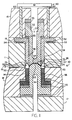
- Figure 2 is a cross-sectional view of a segment of the full invention which shows the annular gate in the actuated extended position forming the side wall of the mold cavity after severing the liquid polymer and during the cure of the polymer.
- the invention is a method and apparatus for injection molding fabrication of optical contact lenses in a closed mold system, and is particularly suitable for use in a reaction injection molding system where multiple liquid polymer components are mixed and injected into the mold cavity, the polymer curing from the chemical reaction of the combined components without need for outside curing from ultraviolet light, heat, etc.
- a reaction injection molding system where multiple liquid polymer components are mixed and injected into the mold cavity, the polymer curing from the chemical reaction of the combined components without need for outside curing from ultraviolet light, heat, etc.
- the apparatus of the invention comprises in general a mold block 10 comprised of an upper mold plate 11 and a lower mold plate 12 which are adapted to mate together to form the mold block 10 and which are typically held together hydraulically during the molding process.
- Upper mold plate 11 is provided with an upper mold bore 13
- lower mold plate 12 is provided with a lower mold bore 14, each positioned so as to align on the same central axis when the upper mold plate 11 and lower mold plate 12 are joined.
- An inlet runner 21 is provided in one or both of upper mold plate 11 and lower mold plate 12, the inlet runner 21 connecting to an inlet port or sprue 22 abutting one or both of the upper mold bore 13 and lower mold bore 14.
- An outlet runner 23 and outlet port 24 are likewise positioned in either one or both upper mold plate 11 and lower mold plate 12.
- the inlet runner 21, inlet port 22, outlet port 24 and outlet runner 23 are shown as positioned in the lower mold plate 12 and abutting the lower mold bore 14.
- the inlet runner 21 is connected to polymer injection apparatus of type well known in the an, which is not shown in the drawings, for injection of the liquid polymer components 99 into the mold in known manner.
- the lower and upper mold bores 14 and 13 are adapted to receive and properly position the component parts which define the mold cavity 15 in which the contact lens is formed.
- the mold cavity 15 is created by providing a back curve insert 51 and a front curve insert 52, the back curve insert 51 having a convex face 53 to define the back wall of the contact lens and the front curve insert 52 having a concave face 54 to define the front wall of the contact lens.
- the curve inserts 51 and 52 are properly positioned within each mold plate 11 and 12 and relative to each other to provide the correct thickness for the mold cavity 15 by the use of various shims 55 and bushings 56 in the currently known manner.
- the curve inserts 51 and 52 are fixed in the mold plates 11 and 12 by attaching upper retainer plate 16 to upper mold plate 11 and lower retainer plate 17 to lower mold plate 12.
- the curve inserts 51 and 52 may be provided with thermocouple ports 57 to insure correct processing parameters, as is also well known in the art.
- annular gate collar 31 Surrounding one of the curve inserts 51 or 52, and preferably surrounding the front insert curve 52 as shown in the drawings, is annular gate collar 31.
- the annular gate 31 is coaxially aligned with the front curve insert 52 and is adapted for movement in the axial direction within upper mold bore 13 relative to the fixed upper mold plate 11 and front curve insert 52.
- the tolerance between the outer wall of the front curve insert 52 and the inner wall 38 of the gated collar 31 should be kept to a minimum, and preferably less than 0.001 inches.
- Annular gate 31 has a flange 32 at its upper end which seats in a flange recess 18 in the upper mold plate 12.
- one or more spring members 33 Positioned between the bottom of the flange 18 and the top of the flange recess 18 are one or more spring members 33.
- actuating means 60 which can comprise any means to rapidly reciprocate gate collar 31 in the axial direction.
- actuating means 60 may comprise one or more pneumatic pistons 61, shown representationally, connected to the gate collar 31 by piston pins 62.
- the lower end of the gate collar 31 is formed as an annular blade 35 having a bevelled outer wall 36, preferably at an angle of approximately 30 degrees, terminating in a non-radiused tip 37 preferably with a thickness of less than .005 inches.
- the tip 37 of gate collar 31 must be able to travel a distance in excess of the thickness of the mold cavity 15, i.e., the separation distance between the convex face 53 and concave face 54.
- the gate collar 31 is adjusted by proper sizing of the apertured shim 34 to allow for travel in the axial direction of approximately 0.15 to 0.20 millimeters.
- the tip 37 of the blade portion 35 does not impede flow of the liquid polymer components 99 into the mold cavity 15.
- the actuating means 60 to reposition the gate collar 31 is activated, pushing the collar 31 downward into the extended position such that the blade tip 37 passes through the liquid polymer 99 and passes the edge of the convex face 53 of the back curve insert 51, as shown in Figure 2.
- the inner wall 38 of the gate collar 31 now forms the circular side wall of the mold cavity 15 as the polymer components 99 react and cure, the mold cavity 15 for the contact lens now consisting of the convex face 53 of the back curve insert 51, the concave face 54 of the front curve insert 52, and the annular inner wall 38 of the gate collar 31.
- Excess polymer 99 is compressed by the bevelled wall 36 into the annular supply recess 19 or forced back into the inlet runner 21 or the outlet runner 23.
- the bevelled wall 36 of the blade 35 also helps to maintain proper axial alignment of the gate collar 31 as it moves through the liquid polymer 99.
- the liquid polymer 99 curing in the mold cavity 15 is not in contact with and is completely separated from the waste liquid polymer 99 at the inlet port 22 or the outlet port 24, and therefore the side wall of the cured contact lens will not require subsequent processing to remove any excess material.
- the mold block 10 is separated and the finished product removed, along with the separate polymer waste now cured in the runners 21 and 23.
Landscapes
- Engineering & Computer Science (AREA)
- Manufacturing & Machinery (AREA)
- Mechanical Engineering (AREA)
- Health & Medical Sciences (AREA)
- Ophthalmology & Optometry (AREA)
- Moulds For Moulding Plastics Or The Like (AREA)
- Casting Or Compression Moulding Of Plastics Or The Like (AREA)
- Eyeglasses (AREA)
Applications Claiming Priority (2)
| Application Number | Priority Date | Filing Date | Title |
|---|---|---|---|
| US576743 | 1995-12-21 | ||
| US08/576,743 US5928682A (en) | 1995-12-21 | 1995-12-21 | Annular gated mold for the injection molding of contact lenses |
Publications (3)
| Publication Number | Publication Date |
|---|---|
| EP0780215A2 true EP0780215A2 (de) | 1997-06-25 |
| EP0780215A3 EP0780215A3 (de) | 1997-10-15 |
| EP0780215B1 EP0780215B1 (de) | 2001-05-30 |
Family
ID=24305807
Family Applications (1)
| Application Number | Title | Priority Date | Filing Date |
|---|---|---|---|
| EP96309385A Expired - Lifetime EP0780215B1 (de) | 1995-12-21 | 1996-12-20 | Form mit ringförmigem Anschnitt zum Spritzgiessen von Kontakt-Linsen |
Country Status (10)
| Country | Link |
|---|---|
| US (1) | US5928682A (de) |
| EP (1) | EP0780215B1 (de) |
| JP (1) | JPH09174609A (de) |
| AT (1) | ATE201628T1 (de) |
| AU (1) | AU716637B2 (de) |
| CA (1) | CA2193450C (de) |
| DE (1) | DE69613088T2 (de) |
| MX (1) | MX9700097A (de) |
| SG (1) | SG89243A1 (de) |
| TW (1) | TW400448B (de) |
Cited By (2)
| Publication number | Priority date | Publication date | Assignee | Title |
|---|---|---|---|---|
| CN103831955A (zh) * | 2012-11-22 | 2014-06-04 | 谢美兰 | 水口剪切设备 |
| CN111907008A (zh) * | 2020-08-04 | 2020-11-10 | 程致远 | 一种塑胶模具 |
Families Citing this family (17)
| Publication number | Priority date | Publication date | Assignee | Title |
|---|---|---|---|---|
| JP4544710B2 (ja) * | 1999-08-27 | 2010-09-15 | 株式会社メニコン | 眼用レンズ物品の成形型及び眼用レンズ物品の製造方法 |
| ATE317758T1 (de) * | 2001-01-24 | 2006-03-15 | Novartis Pharma Gmbh | Verfahren zur herstellung von linsen |
| US20030078658A1 (en) | 2001-01-25 | 2003-04-24 | Gholam-Reza Zadno-Azizi | Single-piece accomodating intraocular lens system |
| US6708397B2 (en) * | 2001-08-09 | 2004-03-23 | Johnson & Johnson Vision Care, Inc. | Inlay station with alignment assemblies and transfer tubes |
| US6939500B2 (en) * | 2001-08-30 | 2005-09-06 | Bernard Mould | Method and apparatus for eliminating a parting line witness mark from a molded part |
| US7615180B2 (en) * | 2005-07-08 | 2009-11-10 | Gentex Optics, Inc. | Method for injection molding with direct insert thermal control |
| EP2206594B1 (de) * | 2007-10-05 | 2017-01-11 | NGK Insulators, Ltd. | Formwerkzeug und formungsverfahren |
| CN101544034A (zh) * | 2008-03-28 | 2009-09-30 | 鸿富锦精密工业(深圳)有限公司 | 模具定位结构 |
| DK2501716T3 (en) | 2009-11-19 | 2015-04-07 | Solis Biodyne Oü | Formations to increase polypeptidstabilitet and activity and related practices |
| SG181663A1 (en) * | 2009-12-17 | 2012-07-30 | Novartis Ag | Method of dosing a lens forming material into a mold |
| US9937640B2 (en) | 2014-12-19 | 2018-04-10 | Coopervision International Holding Company, Lp | Apparatus and method for closure of ophthalmic lens molds |
| US9764501B2 (en) | 2014-12-19 | 2017-09-19 | Coopervision International Holding Company, Lp | Contact lens mold parts, contact lens mold assemblies, and methods of making contact lenses |
| US9938034B2 (en) | 2014-12-19 | 2018-04-10 | Coopervision International Holding Company, Lp | Method and apparatus relating to manufacture of molds for forming contact lenses |
| US10029402B2 (en) | 2014-12-19 | 2018-07-24 | Coopervision International Holding Company, Lp | Method and apparatus for manufacturing contact lenses |
| US10137612B2 (en) | 2014-12-19 | 2018-11-27 | Coopervision International Holding Company, Lp | Methods and apparatus for manufacture of ophthalmic lenses |
| US10786959B2 (en) * | 2016-07-18 | 2020-09-29 | Johnson & Johnson Vision Care, Inc | Mold for contact lens with non-rotationally symmetric rim or edge |
| CN115816765B (zh) * | 2022-11-01 | 2023-06-13 | 南京肯特复合材料股份有限公司 | 一种无气纹的pfa包覆蝶板的成型方法 |
Family Cites Families (10)
| Publication number | Priority date | Publication date | Assignee | Title |
|---|---|---|---|---|
| US2304217A (en) * | 1938-01-20 | 1942-12-08 | American Optical Corp | Method and apparatus for making lenses |
| US4407766A (en) * | 1981-05-26 | 1983-10-04 | National Patent Development Corporation | Molds and procedure for producing truncated contact lenses |
| FR2530181A1 (fr) * | 1982-07-16 | 1984-01-20 | Essilor Int | Procede et dispositif pour le moulage d'un element optique en matiere synthetique |
| US4622089A (en) * | 1983-02-28 | 1986-11-11 | Johnson & Johnson Products, Inc. | Method of making blister pad adhesive bandage |
| JPS60132719A (ja) * | 1983-12-22 | 1985-07-15 | Alps Electric Co Ltd | プラスチツクレンズの製造方法 |
| US4836960A (en) * | 1987-10-05 | 1989-06-06 | Sola Usa, Inc. | Fabrication of thermoplastic optical components by injection/compression molding |
| US5182065A (en) * | 1990-04-30 | 1993-01-26 | Ontario Die Company Limited | Method for producing structural injection molded parts using lost motion movement between a mold and surrounding cutting blade |
| IT1252217B (it) * | 1991-12-16 | 1995-06-05 | Devi Spa | Procedimento e macchina per lo stampaggio di materiale plastico accoppiato. |
| US5405557A (en) * | 1993-04-21 | 1995-04-11 | Sola Group Ltd. | Method of making a moulded photochromic lens |
| JPH07299845A (ja) * | 1994-04-28 | 1995-11-14 | Olympus Optical Co Ltd | ゲートカット装置 |
-
1995
- 1995-12-21 US US08/576,743 patent/US5928682A/en not_active Expired - Lifetime
-
1996
- 1996-12-13 TW TW085115383A patent/TW400448B/zh not_active IP Right Cessation
- 1996-12-18 AU AU75451/96A patent/AU716637B2/en not_active Expired
- 1996-12-19 CA CA002193450A patent/CA2193450C/en not_active Expired - Lifetime
- 1996-12-20 AT AT96309385T patent/ATE201628T1/de not_active IP Right Cessation
- 1996-12-20 SG SG9611870A patent/SG89243A1/en unknown
- 1996-12-20 JP JP8354712A patent/JPH09174609A/ja active Pending
- 1996-12-20 DE DE69613088T patent/DE69613088T2/de not_active Expired - Lifetime
- 1996-12-20 EP EP96309385A patent/EP0780215B1/de not_active Expired - Lifetime
-
1997
- 1997-01-07 MX MX9700097A patent/MX9700097A/es unknown
Non-Patent Citations (1)
| Title |
|---|
| None |
Cited By (3)
| Publication number | Priority date | Publication date | Assignee | Title |
|---|---|---|---|---|
| CN103831955A (zh) * | 2012-11-22 | 2014-06-04 | 谢美兰 | 水口剪切设备 |
| CN111907008A (zh) * | 2020-08-04 | 2020-11-10 | 程致远 | 一种塑胶模具 |
| CN111907008B (zh) * | 2020-08-04 | 2022-03-04 | 勇气模具塑胶(苏州)有限公司 | 一种塑胶模具 |
Also Published As
| Publication number | Publication date |
|---|---|
| DE69613088T2 (de) | 2001-10-18 |
| AU716637B2 (en) | 2000-03-02 |
| DE69613088D1 (de) | 2001-07-05 |
| US5928682A (en) | 1999-07-27 |
| CA2193450A1 (en) | 1997-06-22 |
| ATE201628T1 (de) | 2001-06-15 |
| CA2193450C (en) | 2005-05-24 |
| TW400448B (en) | 2000-08-01 |
| SG89243A1 (en) | 2002-06-18 |
| JPH09174609A (ja) | 1997-07-08 |
| MX9700097A (es) | 1997-06-28 |
| EP0780215B1 (de) | 2001-05-30 |
| EP0780215A3 (de) | 1997-10-15 |
| AU7545196A (en) | 1997-06-26 |
Similar Documents
| Publication | Publication Date | Title |
|---|---|---|
| EP0780215B1 (de) | Form mit ringförmigem Anschnitt zum Spritzgiessen von Kontakt-Linsen | |
| US5415817A (en) | Process for molding plastic lenses | |
| EP0341880A2 (de) | Durch mehrfaches Spritzgiessen geformter Körper, Giessverfahren und Giessmaschine | |
| MXPA97000097A (en) | Mold with any annular gate for molding by injection of conta lenses | |
| EP1136222B1 (de) | Verfahren und gerät zum herstellen von kontaktlinsenteilen und dafür benutzte spritzgussform | |
| JPH07256658A (ja) | 光学レンズを製造する方法および装置 | |
| US3787159A (en) | Apparatus for injection molding with thermosetting resins | |
| EP0778119B1 (de) | Spritzprägeverfahren zum Formen eines Brillenglases | |
| CA2185504A1 (en) | Method and system for gas assisted injection molding with external and internal gas inlets | |
| EP0955147B1 (de) | Verfahren zum spritzgiessen einer kunststofflinse | |
| CN1906010B (zh) | 注射压缩模塑 | |
| JP2686122B2 (ja) | プラスチックレンズの高精度成形方法及びその成形装置 | |
| GB2219243A (en) | Moulding different lenses having the same edge thickness | |
| JP3311685B2 (ja) | 中空体製品の成形方法および成形用金型 | |
| JP2770535B2 (ja) | 多色成形品の成形方法及び成形用金型 | |
| EP1273424B1 (de) | Verfahren zum Spritzgiessen von Kunststofflinsen | |
| JP3326752B2 (ja) | 接合部を有する成形品の成形方法および成形用金型 | |
| JPH069826Y2 (ja) | 射出圧縮成形用金型の逆流防止装置 | |
| JPH10230534A (ja) | 射出圧縮成形方法およびこの方法に用いる射出圧縮成形用金型装置 | |
| JP3156838B2 (ja) | 射出成形用金型 | |
| JPH0716883A (ja) | 射出成形の樹脂充填量制御方法、及びそれを実施する為の樹脂充填量制御装置 | |
| JP2002036306A (ja) | 成形方法およびこの方法に用いるバルブゲート式金型装置 | |
| JPS634488B2 (de) | ||
| JPH0430329B2 (de) | ||
| JPH0919940A (ja) | インサート成形品の成形装置およびその成形方法 |
Legal Events
| Date | Code | Title | Description |
|---|---|---|---|
| PUAI | Public reference made under article 153(3) epc to a published international application that has entered the european phase |
Free format text: ORIGINAL CODE: 0009012 |
|
| AK | Designated contracting states |
Kind code of ref document: A2 Designated state(s): AT BE CH DE DK ES FR GB GR IE IT LI NL PT SE |
|
| PUAL | Search report despatched |
Free format text: ORIGINAL CODE: 0009013 |
|
| AK | Designated contracting states |
Kind code of ref document: A3 Designated state(s): AT BE CH DE DK ES FR GB GR IE IT LI NL PT SE |
|
| 17P | Request for examination filed |
Effective date: 19980320 |
|
| 17Q | First examination report despatched |
Effective date: 19990708 |
|
| GRAG | Despatch of communication of intention to grant |
Free format text: ORIGINAL CODE: EPIDOS AGRA |
|
| GRAG | Despatch of communication of intention to grant |
Free format text: ORIGINAL CODE: EPIDOS AGRA |
|
| GRAH | Despatch of communication of intention to grant a patent |
Free format text: ORIGINAL CODE: EPIDOS IGRA |
|
| GRAH | Despatch of communication of intention to grant a patent |
Free format text: ORIGINAL CODE: EPIDOS IGRA |
|
| GRAA | (expected) grant |
Free format text: ORIGINAL CODE: 0009210 |
|
| AK | Designated contracting states |
Kind code of ref document: B1 Designated state(s): AT BE CH DE DK ES FR GB GR IE IT LI NL PT SE |
|
| PG25 | Lapsed in a contracting state [announced via postgrant information from national office to epo] |
Ref country code: NL Free format text: LAPSE BECAUSE OF FAILURE TO SUBMIT A TRANSLATION OF THE DESCRIPTION OR TO PAY THE FEE WITHIN THE PRESCRIBED TIME-LIMIT Effective date: 20010530 Ref country code: LI Free format text: LAPSE BECAUSE OF FAILURE TO SUBMIT A TRANSLATION OF THE DESCRIPTION OR TO PAY THE FEE WITHIN THE PRESCRIBED TIME-LIMIT Effective date: 20010530 Ref country code: CH Free format text: LAPSE BECAUSE OF FAILURE TO SUBMIT A TRANSLATION OF THE DESCRIPTION OR TO PAY THE FEE WITHIN THE PRESCRIBED TIME-LIMIT Effective date: 20010530 Ref country code: BE Free format text: LAPSE BECAUSE OF FAILURE TO SUBMIT A TRANSLATION OF THE DESCRIPTION OR TO PAY THE FEE WITHIN THE PRESCRIBED TIME-LIMIT Effective date: 20010530 Ref country code: AT Free format text: LAPSE BECAUSE OF FAILURE TO SUBMIT A TRANSLATION OF THE DESCRIPTION OR TO PAY THE FEE WITHIN THE PRESCRIBED TIME-LIMIT Effective date: 20010530 |
|
| REF | Corresponds to: |
Ref document number: 201628 Country of ref document: AT Date of ref document: 20010615 Kind code of ref document: T |
|
| REG | Reference to a national code |
Ref country code: CH Ref legal event code: EP |
|
| REF | Corresponds to: |
Ref document number: 69613088 Country of ref document: DE Date of ref document: 20010705 |
|
| REG | Reference to a national code |
Ref country code: IE Ref legal event code: FG4D |
|
| ITF | It: translation for a ep patent filed | ||
| PG25 | Lapsed in a contracting state [announced via postgrant information from national office to epo] |
Ref country code: SE Free format text: LAPSE BECAUSE OF FAILURE TO SUBMIT A TRANSLATION OF THE DESCRIPTION OR TO PAY THE FEE WITHIN THE PRESCRIBED TIME-LIMIT Effective date: 20010830 Ref country code: PT Free format text: LAPSE BECAUSE OF FAILURE TO SUBMIT A TRANSLATION OF THE DESCRIPTION OR TO PAY THE FEE WITHIN THE PRESCRIBED TIME-LIMIT Effective date: 20010830 Ref country code: DK Free format text: LAPSE BECAUSE OF FAILURE TO SUBMIT A TRANSLATION OF THE DESCRIPTION OR TO PAY THE FEE WITHIN THE PRESCRIBED TIME-LIMIT Effective date: 20010830 |
|
| PG25 | Lapsed in a contracting state [announced via postgrant information from national office to epo] |
Ref country code: GR Free format text: LAPSE BECAUSE OF FAILURE TO SUBMIT A TRANSLATION OF THE DESCRIPTION OR TO PAY THE FEE WITHIN THE PRESCRIBED TIME-LIMIT Effective date: 20010831 |
|
| ET | Fr: translation filed | ||
| NLV1 | Nl: lapsed or annulled due to failure to fulfill the requirements of art. 29p and 29m of the patents act | ||
| PG25 | Lapsed in a contracting state [announced via postgrant information from national office to epo] |
Ref country code: ES Free format text: LAPSE BECAUSE OF FAILURE TO SUBMIT A TRANSLATION OF THE DESCRIPTION OR TO PAY THE FEE WITHIN THE PRESCRIBED TIME-LIMIT Effective date: 20011130 |
|
| REG | Reference to a national code |
Ref country code: CH Ref legal event code: PL |
|
| REG | Reference to a national code |
Ref country code: GB Ref legal event code: IF02 |
|
| PLBE | No opposition filed within time limit |
Free format text: ORIGINAL CODE: 0009261 |
|
| STAA | Information on the status of an ep patent application or granted ep patent |
Free format text: STATUS: NO OPPOSITION FILED WITHIN TIME LIMIT |
|
| 26N | No opposition filed | ||
| REG | Reference to a national code |
Ref country code: FR Ref legal event code: PLFP Year of fee payment: 20 |
|
| PGFP | Annual fee paid to national office [announced via postgrant information from national office to epo] |
Ref country code: FR Payment date: 20150629 Year of fee payment: 20 |
|
| PGFP | Annual fee paid to national office [announced via postgrant information from national office to epo] |
Ref country code: DE Payment date: 20151215 Year of fee payment: 20 Ref country code: GB Payment date: 20151216 Year of fee payment: 20 Ref country code: IE Payment date: 20151209 Year of fee payment: 20 |
|
| PGFP | Annual fee paid to national office [announced via postgrant information from national office to epo] |
Ref country code: IT Payment date: 20151221 Year of fee payment: 20 |
|
| REG | Reference to a national code |
Ref country code: DE Ref legal event code: R071 Ref document number: 69613088 Country of ref document: DE |
|
| REG | Reference to a national code |
Ref country code: GB Ref legal event code: PE20 Expiry date: 20161219 |
|
| REG | Reference to a national code |
Ref country code: IE Ref legal event code: MK9A |
|
| PG25 | Lapsed in a contracting state [announced via postgrant information from national office to epo] |
Ref country code: GB Free format text: LAPSE BECAUSE OF EXPIRATION OF PROTECTION Effective date: 20161219 |
|
| PG25 | Lapsed in a contracting state [announced via postgrant information from national office to epo] |
Ref country code: IE Free format text: LAPSE BECAUSE OF EXPIRATION OF PROTECTION Effective date: 20161220 |