EP0779112B1 - Support de capteurs - Google Patents
Support de capteurs Download PDFInfo
- Publication number
- EP0779112B1 EP0779112B1 EP96250262A EP96250262A EP0779112B1 EP 0779112 B1 EP0779112 B1 EP 0779112B1 EP 96250262 A EP96250262 A EP 96250262A EP 96250262 A EP96250262 A EP 96250262A EP 0779112 B1 EP0779112 B1 EP 0779112B1
- Authority
- EP
- European Patent Office
- Prior art keywords
- measuring device
- contour
- distance sensors
- roll
- tube
- Prior art date
- Legal status (The legal status is an assumption and is not a legal conclusion. Google has not performed a legal analysis and makes no representation as to the accuracy of the status listed.)
- Expired - Lifetime
Links
- 239000002826 coolant Substances 0.000 claims description 16
- 238000005096 rolling process Methods 0.000 claims description 15
- 238000001816 cooling Methods 0.000 claims description 6
- 238000005259 measurement Methods 0.000 description 15
- 239000002184 metal Substances 0.000 description 3
- 238000013016 damping Methods 0.000 description 2
- 238000001514 detection method Methods 0.000 description 2
- 230000002349 favourable effect Effects 0.000 description 2
- 230000000149 penetrating effect Effects 0.000 description 2
- XLYOFNOQVPJJNP-UHFFFAOYSA-N water Substances O XLYOFNOQVPJJNP-UHFFFAOYSA-N 0.000 description 2
- 230000001419 dependent effect Effects 0.000 description 1
- 230000007613 environmental effect Effects 0.000 description 1
- 238000011156 evaluation Methods 0.000 description 1
- 230000001788 irregular Effects 0.000 description 1
- 239000007788 liquid Substances 0.000 description 1
- 239000000463 material Substances 0.000 description 1
- 238000000034 method Methods 0.000 description 1
- 230000036316 preload Effects 0.000 description 1
- 230000001629 suppression Effects 0.000 description 1
Images

Classifications
-
- B—PERFORMING OPERATIONS; TRANSPORTING
- B21—MECHANICAL METAL-WORKING WITHOUT ESSENTIALLY REMOVING MATERIAL; PUNCHING METAL
- B21B—ROLLING OF METAL
- B21B38/00—Methods or devices for measuring, detecting or monitoring specially adapted for metal-rolling mills, e.g. position detection, inspection of the product
- B21B38/12—Methods or devices for measuring, detecting or monitoring specially adapted for metal-rolling mills, e.g. position detection, inspection of the product for measuring roll camber
-
- G—PHYSICS
- G01—MEASURING; TESTING
- G01B—MEASURING LENGTH, THICKNESS OR SIMILAR LINEAR DIMENSIONS; MEASURING ANGLES; MEASURING AREAS; MEASURING IRREGULARITIES OF SURFACES OR CONTOURS
- G01B7/00—Measuring arrangements characterised by the use of electric or magnetic techniques
- G01B7/28—Measuring arrangements characterised by the use of electric or magnetic techniques for measuring contours or curvatures
- G01B7/287—Measuring arrangements characterised by the use of electric or magnetic techniques for measuring contours or curvatures using a plurality of fixed, simultaneously operating transducers
-
- B—PERFORMING OPERATIONS; TRANSPORTING
- B21—MECHANICAL METAL-WORKING WITHOUT ESSENTIALLY REMOVING MATERIAL; PUNCHING METAL
- B21B—ROLLING OF METAL
- B21B1/00—Metal-rolling methods or mills for making semi-finished products of solid or profiled cross-section; Sequence of operations in milling trains; Layout of rolling-mill plant, e.g. grouping of stands; Succession of passes or of sectional pass alternations
- B21B1/22—Metal-rolling methods or mills for making semi-finished products of solid or profiled cross-section; Sequence of operations in milling trains; Layout of rolling-mill plant, e.g. grouping of stands; Succession of passes or of sectional pass alternations for rolling plates, strips, bands or sheets of indefinite length
- B21B1/24—Metal-rolling methods or mills for making semi-finished products of solid or profiled cross-section; Sequence of operations in milling trains; Layout of rolling-mill plant, e.g. grouping of stands; Succession of passes or of sectional pass alternations for rolling plates, strips, bands or sheets of indefinite length in a continuous or semi-continuous process
- B21B1/26—Metal-rolling methods or mills for making semi-finished products of solid or profiled cross-section; Sequence of operations in milling trains; Layout of rolling-mill plant, e.g. grouping of stands; Succession of passes or of sectional pass alternations for rolling plates, strips, bands or sheets of indefinite length in a continuous or semi-continuous process by hot-rolling, e.g. Steckel hot mill
Definitions
- the invention relates to a contour measuring device, in particular for measuring the contour of hot strip rolls installed in the rolling stand during the rolling process.
- a contour measuring device is known from JP abstract 60-180610 A.
- a four-roll stand for rolling metal strips that can be rotated in chocks stored two work and two backup rolls is for example from DE-A-2 260 256 known. Due to the process, there is heavy wear on the rollers Roll surfaces, especially the work rolls. Especially in the area of the edges of the rolling stock, local depressions, so-called Wear marks that occur more frequently if metal strips are continuously the same Rolled wide. With increasing wear of the rollers, therefore Flatness of the rolled metal strips drastically. To prevent or to do this reduce, it is necessary to regrind the rollers at cyclical intervals or to switch. These distances are generally rigid and direct according to the operational experience gained. Because the wear of the rollers is irregular the renewal cycles of the rolls or roll surfaces in not optimal, i.e. performed in the most cost-effective manner.
- a mechanical distance sensor used on roll grinding machines is, for example known from EP-B1-0239161.
- this distance sensor it is not possible, especially due to the unfavorable environmental conditions, especially the high temperatures occurring in the area of the rollers, the contour of the hot ones Measure the roll surface directly in the stand because of thermal expansion the measurement error is too large.
- the measurement takes one Measuring device relatively long, which is disadvantageous in that the thermal bale the roller starts to recede significantly after just one minute, but you First of all, an exact recording of the thermal bale, i.e. the real one Contour of the hot roll surface during the rolling process, interested is.
- a highly precise detection of the roll contour during the rolling process is possible with a such a measuring device is not possible.
- the object of the present invention is a contour measuring device for measurement the roll contour, especially hot strip rolls installed in the roll stand, to create, which makes it possible with high measuring accuracy in every state of wear the contour of the hot roller (the thermal bale) over the entire roller length to determine during the rolling process.
- the invention provides for a longitudinal member extending over the length of the roll a large number of cooled non-contact measuring across the longitudinal axis of the roll Arrange distance sensors with a lateral distance to each other.
- the side member is a double-walled tube with a Inner tube for the passage of a cooling medium and the inner tube under Leaving an annular space surrounding jacket tube is formed. It is Inner tube advantageously attached to the ends of the jacket tube in order to avoid thermal bridges to have in the middle tube area.
- the cooling medium is also expediently used to cool the jacket tube, by its introduction at one end of the inner tube and its return through the annulus.
- a strong thermal decoupling is achieved in that the distance sensors are only attached to the inner tube.
- Openings are provided in the casing tube for carrying out the measurements which the distance sensors left the wall of the casing tube Penetrate annular gap, so that the coolant emerging through the annular gap cooling of the distance sensor heads is ensured.
- the measurement is then carried out with a defined constant temperature for all distance sensors.
- the alternate measurement of the work roll and the backup roll is preferably carried out by tilting the side member about an axis parallel to its longitudinal axis by means of an appropriate tilting device.
- the side member is advantageously from a parking position to a measuring position Traversable parallel to the axis of the roller. This ensures that the side member and the distance sensors only the unfavorable during the measurement period Ambient conditions in the rolling mill are exposed, which in particular the lifespan of the distance sensors is increased.
- the invention can be used both in two-roll stands and on multiple or Four-roll stands apply and both in rolling mills for flat products as well Insert profiles.
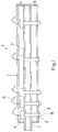
- the side member 1 shows a longitudinal section through the longitudinal member 1 of a contour measuring device, especially for measuring the profile of hot-rolled rolls installed in the roll stand is suitable during the rolling process.
- the side member 1 is how 1 shows, as a hollow profile with a double jacket, preferably as a double jacket tube, formed, the inner tube 2 and the jacket tube 3 coaxially below Leave an annulus 4 are fixed to each other.
- the casing tube 3 In the area of the end faces is the casing tube 3 closed, the inner tube 2, the side wall 5 of the Jacket tube 3 penetrates on one side and on the opposite side the side wall 6 of the casing tube 3 is attached.
- the casing tube 3 and the inner tube 2 are only connected to each other at two points, so that in the middle area there are no further thermal bridges in the double jacket tube.
- the inner tube 2 is on the side penetrating the casing tube 3 with a coolant supply (not shown) connected; Water is usually used as the coolant.
- the inner tube 2 has a plurality of openings 7 through which the pressurized Coolant flows into the annular space 4 during operation of the double jacket tube.
- a plurality of distance sensors 8 with lateral Distance parallel to each other and the inner tube 2 radially penetrating the inner tube 2 attached.
- the distance between the distance sensors 8 can be dependent on one another vary from the desired resolution; experience has shown that it is low Contour changes per unit length of the roller, the distance can be chosen to be relatively large become.
- the distance of the distance sensors must be in the area of strong profile changes 8, on the other hand, should be chosen significantly smaller in order to correctly record the contour profile.
- the distance sensors 8 are aligned parallel to one another and penetrate it Jacket tube 3 radially at specially provided openings 9, so that their measuring heads 10 protrude a little from the casing tube.
- the openings 9 in the casing tube 3 are provided with a larger diameter than the distance sensors 8, which the Coolant can escape through the annular gap formed thereby.
- the electrical Connection lines 11 of the distance sensors 8 are on the jacket openings 9 opposite side through the casing tube 3 and with the corresponding control and evaluation devices (not shown) connected.
- the carrier tube 1 is preloaded can be loaded parallel to its longitudinal axis, for example by tie rods the length of the casing tube are arranged distributed, in particular to one during operation to set the contour measuring device not disturbing natural frequency, d. H. the To shift the natural frequency of the side member into a more favorable range.
- the probability can be a favorable choice of materials and dimensions for the occurrence of undesirable natural vibrations of the side member 1 further decrease.
- the use of hollow bodies with a non-circular, but rather, for example, elliptical cross section is an elegant variant of Suppression of natural frequencies.
- the distance sensors 8 are eddy current sensors, which are particularly good for accurate non-contact due to their insensitivity Distance measurements are suitable.
- the side member is 1 from a protected parking position into a via a sled Measuring position can be moved parallel to the axis of the roller to be measured.
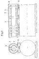
- the bracket of the side member executed so that this by means of a tilting device (also not shown) can be tilted, as can be seen more clearly in FIG. 2.
- a tilting device also not shown
- Fig. 3 shows a schematic representation a cross section and a longitudinal section through the side member in the measuring position the measurement.
- the contour measuring device works as follows:
- the longitudinal beam 1 with the distance sensors 8 move from the parking position into the measuring position parallel to the axis of the roller and the distance sensors 8 by tilting about the longitudinal beam axis radially to the corresponding Aligned roller surface.
- the sensor heads of the distance sensors show 8 a predetermined distance from the roller surface.
- a suitable coolant water is passed into the inner tube 2 for cooling. This flows around the distance sensors 8, whereby they are cooled, and flows through the openings 7 in the inner tube into the annular space of the double jacket tube, so that the jacket tube 3 is also cooled.
- the coolant leaves the side member 1 through the annular gap openings 9 with cooling, in particular of the distance sensor heads 10.
- the emerging coolant forms between the roller surface and the distance sensor head 10 a liquid-vapor atmosphere indicated schematically in FIG. 2 12, which also acts as a heat shield in the area of the distance sensor head 10 acts.
- the only attached to the inner tube distance sensors 8 are by the coolant is cooled in such a way that they all have the same temperature (or the same temperature profile over the sensor length).
- Coolant achieves particularly intensive cooling of the distance sensor heads 10.
- Eddy current sensors are particularly well suited for this type of cooling, because the dielectric coolant does not cause an additional measurement error. Eddy current sensors also make it possible, in addition to determining the roller contour also to detect existing structural changes in the surface area of the roller.
- the Roll deflection is determined, displayed and specifically changed using appropriate actuators are used, among other things, to adjust or readjust the roll gap, thereby the flatness and dimensional accuracy of the tapes can in turn be increased significantly.
Landscapes
- Engineering & Computer Science (AREA)
- Mechanical Engineering (AREA)
- Physics & Mathematics (AREA)
- General Physics & Mathematics (AREA)
- Length Measuring Devices With Unspecified Measuring Means (AREA)
- Measurement Of Length, Angles, Or The Like Using Electric Or Magnetic Means (AREA)
Claims (10)
- Dispositif de mesure de contour pour mesurer le contour de cylindres pour feuillards laminés à chaud montés dans la cage de laminoir lors du processus de laminage, comportant au moins un capteur de proximité (8), dont la tête de mesure (10) est alignée sur la surface des cylindres, une pluralité de capteurs de proximité (8) mesurant sans contact étant agencés à distance latérale les uns des autres sur un support longitudinal (1) s'étendant sur la longueur des cylindres transversalement à l'axe longitudinal des cylindres,
caractérisé en ce que le support longitudinal (1), pour refroidir les capteurs de proximité (8), est réalisé comme tube à double enveloppe ayant un tube interne (2) pour transporter un fluide de refroidissement et un tube d'enveloppe (3) entourant le tube interne (2) en laissant un espace annulaire (4), le tube interne (2) étant fixé aux extrémités par rapport au tube d'enveloppe (3). - Dispositif de mesure de contour selon la revendication 1,
caractérisé en ce que le support longitudinal (1) est réalisé de sorte que le fluide de refroidissement peut être introduit à une extrémité dans le tube interne (2), et en ce qu'une circulation en retour du fluide de refroidissement est effectuée à travers l'espace annulaire (4). - Dispositif de mesure de contour selon la revendication 1 ou 2,
caractérisé en ce que les capteurs de proximité (8) sont fixés au tube interne (2). - Dispositif de mesure de contour selon une ou plusieurs des revendications 1 à 3,
caractérisé en ce que, dans le tube d'enveloppe (3), sont prévues des ouvertures (9) à travers lesquelles les capteurs de proximité (8) traversent la paroi du tube d'enveloppe (3). - Dispositif de mesure de contour selon la revendication 4,
caractérisé en ce que les capteurs de proximité (8) traversent les ouvertures (9) en laissant une fente annulaire. - Dispositif de mesure de contour selon une ou plusieurs des revendications 1 à 5,
caractérisé en ce qu'une précontrainte est appliquée au support longitudinal (1) en direction de son axe longitudinal. - Dispositif de mesure de contour selon une ou plusieurs des revendications 1 à 6,
caractérisé en ce que le support longitudinal (1) présente un dispositif de basculement pour basculer autour d'un axe parallèle à son axe longitudinal. - Dispositif de mesure de contour selon une ou plusieurs des revendications 1 à 7,
caractérisé en ce que les capteurs de proximité (8) sont réalisés comme capteurs de courants parasites. - Dispositif de mesure de contour selon une ou plusieurs des revendications 1 à 8,
caractérisé en ce que les capteurs de proximité (8) sont alignés parallèlement les uns aux autres et radialement sur la surface des cylindres. - Dispositif de mesure de contour selon la revendication 1,
caractérisé en ce que le support longitudinal (1) est déplacable d'une position d'attente dans une position de mesure parallèlement à l'axe du cylindre.
Applications Claiming Priority (2)
| Application Number | Priority Date | Filing Date | Title |
|---|---|---|---|
| DE19547438 | 1995-12-11 | ||
| DE19547438A DE19547438C2 (de) | 1995-12-11 | 1995-12-11 | Sensorträger |
Publications (2)
| Publication Number | Publication Date |
|---|---|
| EP0779112A1 EP0779112A1 (fr) | 1997-06-18 |
| EP0779112B1 true EP0779112B1 (fr) | 1999-09-29 |
Family
ID=7780570
Family Applications (1)
| Application Number | Title | Priority Date | Filing Date |
|---|---|---|---|
| EP96250262A Expired - Lifetime EP0779112B1 (fr) | 1995-12-11 | 1996-11-19 | Support de capteurs |
Country Status (3)
| Country | Link |
|---|---|
| US (1) | US5918493A (fr) |
| EP (1) | EP0779112B1 (fr) |
| DE (2) | DE19547438C2 (fr) |
Families Citing this family (5)
| Publication number | Priority date | Publication date | Assignee | Title |
|---|---|---|---|---|
| DE19844305A1 (de) * | 1998-09-17 | 2000-03-30 | Mannesmann Ag | Kombiniertes Regelungssystem zur Erzeugung bestimmter Produkteigenschaften beim Walzen von Stahlqualitäten im austenitischen, gemischt austenitisch-ferritischen und ferritischen Bereich |
| DE10003496A1 (de) * | 2000-01-27 | 2001-08-09 | Siemens Ag | Vorrichtung zur Messung der Kontur, der horizontalen Krümmung und/oder der horizontalen Position einer Walze eines Walzgerüsts |
| DE10063773A1 (de) * | 2000-12-21 | 2002-06-27 | Sms Demag Ag | Konturmeßeinrichtung und Verfahren zur Messung einer Kontur |
| NO2755812T3 (fr) | 2013-03-12 | 2018-06-30 | ||
| JP6361243B2 (ja) * | 2014-04-07 | 2018-07-25 | 株式会社ジェイテクト | 加工変質検出センサを備える工作機械 |
Family Cites Families (11)
| Publication number | Priority date | Publication date | Assignee | Title |
|---|---|---|---|---|
| JPS517635B2 (fr) * | 1971-12-10 | 1976-03-09 | ||
| GB1507987A (en) * | 1974-07-15 | 1978-04-19 | British Steel Corp | Mill stand roll parameter monitor |
| GB2136128B (en) * | 1983-03-01 | 1986-10-22 | British Steel Corp | Improvements in or relating to the measurement of surface profile |
| JPS60180610A (ja) | 1984-02-27 | 1985-09-14 | Sumitomo Light Metal Ind Ltd | 圧延ロ−ルクラウンの測定方法 |
| IT1191688B (it) * | 1986-03-20 | 1988-03-23 | Giustina International Spa | Macchina rettificatrice per cilindri con organi di rilievo e controllo dimensionale e superficiale |
| JPS62220206A (ja) * | 1986-03-20 | 1987-09-28 | Ishikawajima Harima Heavy Ind Co Ltd | ロ−ルギヤツプの検出装置 |
| JPS63282393A (ja) * | 1987-05-09 | 1988-11-18 | 株式会社ササクラ | 回転ローラ式冷却装置 |
| JP2837219B2 (ja) * | 1990-03-02 | 1998-12-14 | 株式会社日立製作所 | ロールプロファイルの測定方法および装置 |
| CH688180A5 (de) * | 1991-02-01 | 1997-06-13 | Pechiney Rhenalu | Messeinrichtung zur Walzspaltregelung. |
| US5317386A (en) * | 1991-09-06 | 1994-05-31 | Eastman Kodak Company | Optical monitor for measuring a gap between two rollers |
| FR2726210B1 (fr) * | 1994-10-28 | 1997-01-10 | Usinor Sacilor | Mise en forme de produits metalliques minces entre deux cylindres |
-
1995
- 1995-12-11 DE DE19547438A patent/DE19547438C2/de not_active Expired - Fee Related
-
1996
- 1996-11-19 EP EP96250262A patent/EP0779112B1/fr not_active Expired - Lifetime
- 1996-11-19 DE DE59603222T patent/DE59603222D1/de not_active Expired - Fee Related
- 1996-12-10 US US08/763,231 patent/US5918493A/en not_active Expired - Fee Related
Also Published As
| Publication number | Publication date |
|---|---|
| DE19547438C2 (de) | 2001-08-16 |
| US5918493A (en) | 1999-07-06 |
| DE19547438A1 (de) | 1997-06-12 |
| DE59603222D1 (de) | 1999-11-04 |
| EP0779112A1 (fr) | 1997-06-18 |
Similar Documents
| Publication | Publication Date | Title |
|---|---|---|
| DE3036997C2 (fr) | ||
| EP1369186B1 (fr) | Procédé et dispositif de mesure de la planéité d'une bande | |
| DE69515251T2 (de) | Formen von dünnen metallurgischen Produkten zwischen zwei Zylindern | |
| EP0523205B1 (fr) | Installation de laminage ou de laminage et coulage avec dispositif de mesure utile pour regler l'emprise et son procede d'exploitation | |
| DE102006024761A1 (de) | Vorrichtung zum Messen der Breite und/oder der Bandlage eines Metallbandes oder einer Bramme | |
| DE3736999A1 (de) | Verfahren zur walzkraftmessung an walzwerkswalzen | |
| DE2626312A1 (de) | Ablenk-walze zum messen der planheit eines laufenden, gespannten blechs o.dgl. | |
| EP0779112B1 (fr) | Support de capteurs | |
| EP0779113B1 (fr) | Dispositif de mesure du profil des cylindres d'un laminoir | |
| DE69620849T2 (de) | Bandformmessgerät | |
| EP1453620A1 (fr) | Dispositif de mesure de l'emprise entre les cylindres de travail d'une structure de laminage a froid ou a chaud | |
| EP0698428B1 (fr) | Dispositif pour détecter l'emprise entre deux cylindres de travail d'une cage de laminoir | |
| DE69820055T2 (de) | Apparat und methode für das messen der temperatur einer sich bewegenden oberfläche | |
| WO1998055243A1 (fr) | Procede et dispositif pour detecter l'etat reel d'un tube chaud | |
| DE2238509A1 (de) | Hydraulische presse und verfahren zu ihrem betrieb | |
| DE10157792B4 (de) | Verfahren und Messrolle zur Messung der Bandzugspannung und/oder der Bandtemperatur über die Bandbreite für eine Bandplanheitsregelung beim Walzen von Bandmaterial | |
| EP1120628B1 (fr) | Poutres de mesure avec cylindre d'un ensemble de cylindrage avec dispositif de compensation | |
| DE3213306A1 (de) | Messvorrichtung zum messen der exzentrizitaet einer walze | |
| EP0918211A1 (fr) | Sonde capacitive de mesure d'épaisseur de film avec sonde inductive de correction | |
| DE102005031289B3 (de) | Vorrichtung und Verfahren zur Messung der Temperatur eines bewegten Körpers | |
| EP0383749B1 (fr) | Dispositif de surveillance de l'écartement de surfaces de jonction de rails, par exemple aux points de dilatation | |
| DE68903738T2 (de) | Warmwalzen von metallband. | |
| EP1210992A2 (fr) | Dispositif pour mesurer le contour d'un cylindre dans une cage de laminoir | |
| EP3784423B1 (fr) | Laminoir à cylindres obliques à ajustement hydraulique des cylindres | |
| DE10202526B4 (de) | Einrichtung zur Messung des Walzspaltes zwischen Arbeitswalzen eines Kalt- oder Warmwalzgerüstes |
Legal Events
| Date | Code | Title | Description |
|---|---|---|---|
| PUAI | Public reference made under article 153(3) epc to a published international application that has entered the european phase |
Free format text: ORIGINAL CODE: 0009012 |
|
| AK | Designated contracting states |
Kind code of ref document: A1 Designated state(s): BE DE FR GB IT SE |
|
| 17P | Request for examination filed |
Effective date: 19970526 |
|
| GRAG | Despatch of communication of intention to grant |
Free format text: ORIGINAL CODE: EPIDOS AGRA |
|
| GRAG | Despatch of communication of intention to grant |
Free format text: ORIGINAL CODE: EPIDOS AGRA |
|
| GRAH | Despatch of communication of intention to grant a patent |
Free format text: ORIGINAL CODE: EPIDOS IGRA |
|
| 17Q | First examination report despatched |
Effective date: 19990212 |
|
| GRAH | Despatch of communication of intention to grant a patent |
Free format text: ORIGINAL CODE: EPIDOS IGRA |
|
| GRAA | (expected) grant |
Free format text: ORIGINAL CODE: 0009210 |
|
| AK | Designated contracting states |
Kind code of ref document: B1 Designated state(s): BE DE FR GB IT SE |
|
| GBT | Gb: translation of ep patent filed (gb section 77(6)(a)/1977) |
Effective date: 19990929 |
|
| REF | Corresponds to: |
Ref document number: 59603222 Country of ref document: DE Date of ref document: 19991104 |
|
| ITF | It: translation for a ep patent filed | ||
| ET | Fr: translation filed | ||
| PLBE | No opposition filed within time limit |
Free format text: ORIGINAL CODE: 0009261 |
|
| STAA | Information on the status of an ep patent application or granted ep patent |
Free format text: STATUS: NO OPPOSITION FILED WITHIN TIME LIMIT |
|
| 26N | No opposition filed | ||
| REG | Reference to a national code |
Ref country code: GB Ref legal event code: IF02 |
|
| PGFP | Annual fee paid to national office [announced via postgrant information from national office to epo] |
Ref country code: GB Payment date: 20031029 Year of fee payment: 8 |
|
| PGFP | Annual fee paid to national office [announced via postgrant information from national office to epo] |
Ref country code: SE Payment date: 20031103 Year of fee payment: 8 Ref country code: DE Payment date: 20031103 Year of fee payment: 8 |
|
| PGFP | Annual fee paid to national office [announced via postgrant information from national office to epo] |
Ref country code: FR Payment date: 20031107 Year of fee payment: 8 |
|
| PGFP | Annual fee paid to national office [announced via postgrant information from national office to epo] |
Ref country code: BE Payment date: 20031209 Year of fee payment: 8 |
|
| PG25 | Lapsed in a contracting state [announced via postgrant information from national office to epo] |
Ref country code: GB Free format text: LAPSE BECAUSE OF NON-PAYMENT OF DUE FEES Effective date: 20041119 |
|
| PG25 | Lapsed in a contracting state [announced via postgrant information from national office to epo] |
Ref country code: SE Free format text: LAPSE BECAUSE OF NON-PAYMENT OF DUE FEES Effective date: 20041120 |
|
| PG25 | Lapsed in a contracting state [announced via postgrant information from national office to epo] |
Ref country code: BE Free format text: LAPSE BECAUSE OF NON-PAYMENT OF DUE FEES Effective date: 20041130 |
|
| BERE | Be: lapsed |
Owner name: *MANNESMANN A.G. Effective date: 20041130 |
|
| PG25 | Lapsed in a contracting state [announced via postgrant information from national office to epo] |
Ref country code: DE Free format text: LAPSE BECAUSE OF NON-PAYMENT OF DUE FEES Effective date: 20050601 |
|
| EUG | Se: european patent has lapsed | ||
| GBPC | Gb: european patent ceased through non-payment of renewal fee |
Effective date: 20041119 |
|
| PG25 | Lapsed in a contracting state [announced via postgrant information from national office to epo] |
Ref country code: FR Free format text: LAPSE BECAUSE OF NON-PAYMENT OF DUE FEES Effective date: 20050729 |
|
| REG | Reference to a national code |
Ref country code: FR Ref legal event code: ST |
|
| PG25 | Lapsed in a contracting state [announced via postgrant information from national office to epo] |
Ref country code: IT Free format text: LAPSE BECAUSE OF NON-PAYMENT OF DUE FEES;WARNING: LAPSES OF ITALIAN PATENTS WITH EFFECTIVE DATE BEFORE 2007 MAY HAVE OCCURRED AT ANY TIME BEFORE 2007. THE CORRECT EFFECTIVE DATE MAY BE DIFFERENT FROM THE ONE RECORDED. Effective date: 20051119 |
|
| BERE | Be: lapsed |
Owner name: *MANNESMANN A.G. Effective date: 20041130 |