EP0779112B1 - Sensor support - Google Patents
Sensor support Download PDFInfo
- Publication number
- EP0779112B1 EP0779112B1 EP96250262A EP96250262A EP0779112B1 EP 0779112 B1 EP0779112 B1 EP 0779112B1 EP 96250262 A EP96250262 A EP 96250262A EP 96250262 A EP96250262 A EP 96250262A EP 0779112 B1 EP0779112 B1 EP 0779112B1
- Authority
- EP
- European Patent Office
- Prior art keywords
- measuring device
- contour
- distance sensors
- roll
- tube
- Prior art date
- Legal status (The legal status is an assumption and is not a legal conclusion. Google has not performed a legal analysis and makes no representation as to the accuracy of the status listed.)
- Expired - Lifetime
Links
- 239000002826 coolant Substances 0.000 claims description 16
- 238000005096 rolling process Methods 0.000 claims description 15
- 238000001816 cooling Methods 0.000 claims description 6
- 238000005259 measurement Methods 0.000 description 15
- 239000002184 metal Substances 0.000 description 3
- 238000013016 damping Methods 0.000 description 2
- 238000001514 detection method Methods 0.000 description 2
- 230000002349 favourable effect Effects 0.000 description 2
- 230000000149 penetrating effect Effects 0.000 description 2
- XLYOFNOQVPJJNP-UHFFFAOYSA-N water Substances O XLYOFNOQVPJJNP-UHFFFAOYSA-N 0.000 description 2
- 230000001419 dependent effect Effects 0.000 description 1
- 230000007613 environmental effect Effects 0.000 description 1
- 238000011156 evaluation Methods 0.000 description 1
- 230000001788 irregular Effects 0.000 description 1
- 239000007788 liquid Substances 0.000 description 1
- 239000000463 material Substances 0.000 description 1
- 238000000034 method Methods 0.000 description 1
- 230000036316 preload Effects 0.000 description 1
- 230000001629 suppression Effects 0.000 description 1
Images

Classifications
-
- B—PERFORMING OPERATIONS; TRANSPORTING
- B21—MECHANICAL METAL-WORKING WITHOUT ESSENTIALLY REMOVING MATERIAL; PUNCHING METAL
- B21B—ROLLING OF METAL
- B21B38/00—Methods or devices for measuring, detecting or monitoring specially adapted for metal-rolling mills, e.g. position detection, inspection of the product
- B21B38/12—Methods or devices for measuring, detecting or monitoring specially adapted for metal-rolling mills, e.g. position detection, inspection of the product for measuring roll camber
-
- G—PHYSICS
- G01—MEASURING; TESTING
- G01B—MEASURING LENGTH, THICKNESS OR SIMILAR LINEAR DIMENSIONS; MEASURING ANGLES; MEASURING AREAS; MEASURING IRREGULARITIES OF SURFACES OR CONTOURS
- G01B7/00—Measuring arrangements characterised by the use of electric or magnetic techniques
- G01B7/28—Measuring arrangements characterised by the use of electric or magnetic techniques for measuring contours or curvatures
- G01B7/287—Measuring arrangements characterised by the use of electric or magnetic techniques for measuring contours or curvatures using a plurality of fixed, simultaneously operating transducers
-
- B—PERFORMING OPERATIONS; TRANSPORTING
- B21—MECHANICAL METAL-WORKING WITHOUT ESSENTIALLY REMOVING MATERIAL; PUNCHING METAL
- B21B—ROLLING OF METAL
- B21B1/00—Metal-rolling methods or mills for making semi-finished products of solid or profiled cross-section; Sequence of operations in milling trains; Layout of rolling-mill plant, e.g. grouping of stands; Succession of passes or of sectional pass alternations
- B21B1/22—Metal-rolling methods or mills for making semi-finished products of solid or profiled cross-section; Sequence of operations in milling trains; Layout of rolling-mill plant, e.g. grouping of stands; Succession of passes or of sectional pass alternations for rolling plates, strips, bands or sheets of indefinite length
- B21B1/24—Metal-rolling methods or mills for making semi-finished products of solid or profiled cross-section; Sequence of operations in milling trains; Layout of rolling-mill plant, e.g. grouping of stands; Succession of passes or of sectional pass alternations for rolling plates, strips, bands or sheets of indefinite length in a continuous or semi-continuous process
- B21B1/26—Metal-rolling methods or mills for making semi-finished products of solid or profiled cross-section; Sequence of operations in milling trains; Layout of rolling-mill plant, e.g. grouping of stands; Succession of passes or of sectional pass alternations for rolling plates, strips, bands or sheets of indefinite length in a continuous or semi-continuous process by hot-rolling, e.g. Steckel hot mill
Definitions
- the invention relates to a contour measuring device, in particular for measuring the contour of hot strip rolls installed in the rolling stand during the rolling process.
- a contour measuring device is known from JP abstract 60-180610 A.
- a four-roll stand for rolling metal strips that can be rotated in chocks stored two work and two backup rolls is for example from DE-A-2 260 256 known. Due to the process, there is heavy wear on the rollers Roll surfaces, especially the work rolls. Especially in the area of the edges of the rolling stock, local depressions, so-called Wear marks that occur more frequently if metal strips are continuously the same Rolled wide. With increasing wear of the rollers, therefore Flatness of the rolled metal strips drastically. To prevent or to do this reduce, it is necessary to regrind the rollers at cyclical intervals or to switch. These distances are generally rigid and direct according to the operational experience gained. Because the wear of the rollers is irregular the renewal cycles of the rolls or roll surfaces in not optimal, i.e. performed in the most cost-effective manner.
- a mechanical distance sensor used on roll grinding machines is, for example known from EP-B1-0239161.
- this distance sensor it is not possible, especially due to the unfavorable environmental conditions, especially the high temperatures occurring in the area of the rollers, the contour of the hot ones Measure the roll surface directly in the stand because of thermal expansion the measurement error is too large.
- the measurement takes one Measuring device relatively long, which is disadvantageous in that the thermal bale the roller starts to recede significantly after just one minute, but you First of all, an exact recording of the thermal bale, i.e. the real one Contour of the hot roll surface during the rolling process, interested is.
- a highly precise detection of the roll contour during the rolling process is possible with a such a measuring device is not possible.
- the object of the present invention is a contour measuring device for measurement the roll contour, especially hot strip rolls installed in the roll stand, to create, which makes it possible with high measuring accuracy in every state of wear the contour of the hot roller (the thermal bale) over the entire roller length to determine during the rolling process.
- the invention provides for a longitudinal member extending over the length of the roll a large number of cooled non-contact measuring across the longitudinal axis of the roll Arrange distance sensors with a lateral distance to each other.
- the side member is a double-walled tube with a Inner tube for the passage of a cooling medium and the inner tube under Leaving an annular space surrounding jacket tube is formed. It is Inner tube advantageously attached to the ends of the jacket tube in order to avoid thermal bridges to have in the middle tube area.
- the cooling medium is also expediently used to cool the jacket tube, by its introduction at one end of the inner tube and its return through the annulus.
- a strong thermal decoupling is achieved in that the distance sensors are only attached to the inner tube.
- Openings are provided in the casing tube for carrying out the measurements which the distance sensors left the wall of the casing tube Penetrate annular gap, so that the coolant emerging through the annular gap cooling of the distance sensor heads is ensured.
- the measurement is then carried out with a defined constant temperature for all distance sensors.
- the alternate measurement of the work roll and the backup roll is preferably carried out by tilting the side member about an axis parallel to its longitudinal axis by means of an appropriate tilting device.
- the side member is advantageously from a parking position to a measuring position Traversable parallel to the axis of the roller. This ensures that the side member and the distance sensors only the unfavorable during the measurement period Ambient conditions in the rolling mill are exposed, which in particular the lifespan of the distance sensors is increased.
- the invention can be used both in two-roll stands and on multiple or Four-roll stands apply and both in rolling mills for flat products as well Insert profiles.
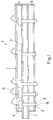
- the side member 1 shows a longitudinal section through the longitudinal member 1 of a contour measuring device, especially for measuring the profile of hot-rolled rolls installed in the roll stand is suitable during the rolling process.
- the side member 1 is how 1 shows, as a hollow profile with a double jacket, preferably as a double jacket tube, formed, the inner tube 2 and the jacket tube 3 coaxially below Leave an annulus 4 are fixed to each other.
- the casing tube 3 In the area of the end faces is the casing tube 3 closed, the inner tube 2, the side wall 5 of the Jacket tube 3 penetrates on one side and on the opposite side the side wall 6 of the casing tube 3 is attached.
- the casing tube 3 and the inner tube 2 are only connected to each other at two points, so that in the middle area there are no further thermal bridges in the double jacket tube.
- the inner tube 2 is on the side penetrating the casing tube 3 with a coolant supply (not shown) connected; Water is usually used as the coolant.
- the inner tube 2 has a plurality of openings 7 through which the pressurized Coolant flows into the annular space 4 during operation of the double jacket tube.
- a plurality of distance sensors 8 with lateral Distance parallel to each other and the inner tube 2 radially penetrating the inner tube 2 attached.
- the distance between the distance sensors 8 can be dependent on one another vary from the desired resolution; experience has shown that it is low Contour changes per unit length of the roller, the distance can be chosen to be relatively large become.
- the distance of the distance sensors must be in the area of strong profile changes 8, on the other hand, should be chosen significantly smaller in order to correctly record the contour profile.
- the distance sensors 8 are aligned parallel to one another and penetrate it Jacket tube 3 radially at specially provided openings 9, so that their measuring heads 10 protrude a little from the casing tube.
- the openings 9 in the casing tube 3 are provided with a larger diameter than the distance sensors 8, which the Coolant can escape through the annular gap formed thereby.
- the electrical Connection lines 11 of the distance sensors 8 are on the jacket openings 9 opposite side through the casing tube 3 and with the corresponding control and evaluation devices (not shown) connected.
- the carrier tube 1 is preloaded can be loaded parallel to its longitudinal axis, for example by tie rods the length of the casing tube are arranged distributed, in particular to one during operation to set the contour measuring device not disturbing natural frequency, d. H. the To shift the natural frequency of the side member into a more favorable range.
- the probability can be a favorable choice of materials and dimensions for the occurrence of undesirable natural vibrations of the side member 1 further decrease.
- the use of hollow bodies with a non-circular, but rather, for example, elliptical cross section is an elegant variant of Suppression of natural frequencies.
- the distance sensors 8 are eddy current sensors, which are particularly good for accurate non-contact due to their insensitivity Distance measurements are suitable.
- the side member is 1 from a protected parking position into a via a sled Measuring position can be moved parallel to the axis of the roller to be measured.
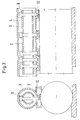
- the bracket of the side member executed so that this by means of a tilting device (also not shown) can be tilted, as can be seen more clearly in FIG. 2.
- a tilting device also not shown
- Fig. 3 shows a schematic representation a cross section and a longitudinal section through the side member in the measuring position the measurement.
- the contour measuring device works as follows:
- the longitudinal beam 1 with the distance sensors 8 move from the parking position into the measuring position parallel to the axis of the roller and the distance sensors 8 by tilting about the longitudinal beam axis radially to the corresponding Aligned roller surface.
- the sensor heads of the distance sensors show 8 a predetermined distance from the roller surface.
- a suitable coolant water is passed into the inner tube 2 for cooling. This flows around the distance sensors 8, whereby they are cooled, and flows through the openings 7 in the inner tube into the annular space of the double jacket tube, so that the jacket tube 3 is also cooled.
- the coolant leaves the side member 1 through the annular gap openings 9 with cooling, in particular of the distance sensor heads 10.
- the emerging coolant forms between the roller surface and the distance sensor head 10 a liquid-vapor atmosphere indicated schematically in FIG. 2 12, which also acts as a heat shield in the area of the distance sensor head 10 acts.
- the only attached to the inner tube distance sensors 8 are by the coolant is cooled in such a way that they all have the same temperature (or the same temperature profile over the sensor length).
- Coolant achieves particularly intensive cooling of the distance sensor heads 10.
- Eddy current sensors are particularly well suited for this type of cooling, because the dielectric coolant does not cause an additional measurement error. Eddy current sensors also make it possible, in addition to determining the roller contour also to detect existing structural changes in the surface area of the roller.
- the Roll deflection is determined, displayed and specifically changed using appropriate actuators are used, among other things, to adjust or readjust the roll gap, thereby the flatness and dimensional accuracy of the tapes can in turn be increased significantly.
Landscapes
- Engineering & Computer Science (AREA)
- Mechanical Engineering (AREA)
- Physics & Mathematics (AREA)
- General Physics & Mathematics (AREA)
- Length Measuring Devices With Unspecified Measuring Means (AREA)
- Measurement Of Length, Angles, Or The Like Using Electric Or Magnetic Means (AREA)
Description
Die Erfindung betrifft eine Konturmeßeinrichtung, insbesondere zur Messung der
Kontur von im Walzgerüst eingebauten Warmbandwalzen beim Walzvorgang gemäß
dem Oberbegriff des Anspruchs 1.
Eine derartige Meßeinrichtung ist aus dem JP-Abstract 60-180610 A bekannt.The invention relates to a contour measuring device, in particular for measuring the contour of hot strip rolls installed in the rolling stand during the rolling process.
Such a measuring device is known from JP abstract 60-180610 A.
Ein Vierwalzengerüst zum Walzen von Metallbändern mit in Einbaustücken drehbar gelagerten zwei Arbeits- sowie zwei Stützwalzen ist beispielsweise aus der DE-A-2 260 256 bekannt. Prozeßbedingt kommt es beim Walzen zu einem starken Verschleiß der Walzenoberflächen, vor allem der Arbeitswalzen. Besonders im Bereich der Kanten des Walzgutes entstehen in der Walzenoberfläche lokale Vertiefungen, sogenannte Verschleißmarken, die verstärkt auftreten, wenn fortlaufend Metallbänder gleicher Breite gewalzt werden. Mit fortschreitendem Verschleiß der Walzen nimmt deshalb die Planheit der gewalzten Metallbänder drastisch ab. Um dies zu verhindern bzw. zu vermindern, ist es erforderlich, die Walzen in zyklischen Abständen nachzuschleifen oder zu wechseln. Diese Abstände sind im allgemeinen starr festgelegt und richten sich nach den gewonnenen Betriebserfahrungen. Da der Verschleiß der Walzen unregelmäßig ist, werden die Erneuerungszyklen der Walzen bzw. Walzenoberflächen in nicht optimaler, d.h. kostengünstigster Weise durchgeführt.A four-roll stand for rolling metal strips that can be rotated in chocks stored two work and two backup rolls is for example from DE-A-2 260 256 known. Due to the process, there is heavy wear on the rollers Roll surfaces, especially the work rolls. Especially in the area of the edges of the rolling stock, local depressions, so-called Wear marks that occur more frequently if metal strips are continuously the same Rolled wide. With increasing wear of the rollers, therefore Flatness of the rolled metal strips drastically. To prevent or to do this reduce, it is necessary to regrind the rollers at cyclical intervals or to switch. These distances are generally rigid and direct according to the operational experience gained. Because the wear of the rollers is irregular the renewal cycles of the rolls or roll surfaces in not optimal, i.e. performed in the most cost-effective manner.
Will man den exakten Zeitpunkt für ein Nachschleifen oder Auswechseln der Walze erkennen, so ist es erforderlich, den Verschleiß der Walzen kontinuierlich zu erfassen. Das kann z.B. durch die Messung der Kontur der Walzenoberfläche in entsprechenden zeitlichen Abständen mit entsprechender Meßgenauigkeit geschehen. Aus der Differenz zwischen ursprünglicher und aktueller Walzenkontur läßt sich dann der Verschleiß der Walze exakt bestimmen. Üblicherweise wird zum Messen ein Abstandssensor längs über die Walzenoberfläche geführt.If you want the exact time for regrinding or changing the roller recognize, it is necessary to continuously record the wear of the rollers. This can e.g. by measuring the contour of the roll surface in corresponding time intervals with appropriate measurement accuracy. From the difference The wear can then be separated between the original and the current roller contour of the roller exactly. A distance sensor is usually used for measuring led lengthways over the roller surface.
Ein an Walzenschleifmaschinen eingesetzter mechanischer Abstandssensor ist beispielsweise aus der EP-B1-0239161 bekannt. Mit diesem Abstandssensor ist es aber nicht möglich, insbesondere aufgrund der ungünstigen Umfeldbedingungen, speziell der hohen im Bereich der Walzen auftretenden Temperaturen, die Kontur der heißen Walzenoberfläche direkt im Gerüst zu messen, da aufgrund von thermischen Dehnungen der Meßfehler zu groß ist. Außerdem dauert die Messung mit einer solchen Meßeinrichtung relativ lange, was insofern von Nachteil ist, da der thermische Ballen der Walze sich bereits nach einer Minute deutlich zurückzubilden beginnt, man aber in erster Linie an einer exakten Erfassung auch des thermischen Ballens, d.h. der wirklichen Kontur der heißen Walzenoberfläche während des Walzprozesses, interessiert ist. Eine hochgenaue Erfassung der Walzenkontur beim Walzvorgang ist mit einer derartigen Meßeinrichtung nicht möglich.A mechanical distance sensor used on roll grinding machines is, for example known from EP-B1-0239161. With this distance sensor it is not possible, especially due to the unfavorable environmental conditions, especially the high temperatures occurring in the area of the rollers, the contour of the hot ones Measure the roll surface directly in the stand because of thermal expansion the measurement error is too large. In addition, the measurement takes one Measuring device relatively long, which is disadvantageous in that the thermal bale the roller starts to recede significantly after just one minute, but you First of all, an exact recording of the thermal bale, i.e. the real one Contour of the hot roll surface during the rolling process, interested is. A highly precise detection of the roll contour during the rolling process is possible with a such a measuring device is not possible.
Es ist Aufgabe der vorliegenden Erfindung, eine Konturmeßeinrichtung zur Messung der Walzenkontur, insbesondere von im Walzgerüst eingebauten Warmbandwalzen, zu schaffen, die es ermöglicht, mit hoher Meßgenauigkeit in jedem Verschleißzustand die Kontur der heißen Walze (den thermischen Ballen) über die gesamte Walzenlänge beim Walzvorgang zu ermitteln.The object of the present invention is a contour measuring device for measurement the roll contour, especially hot strip rolls installed in the roll stand, to create, which makes it possible with high measuring accuracy in every state of wear the contour of the hot roller (the thermal bale) over the entire roller length to determine during the rolling process.
Die Lösung dieser Aufgabe ist erfindungsgemäß gekennzeichnet durch die im Patentanspruch
1 angegebenen Merkmale. Durch die kennzeichnenden Merkmale der Unteransprüche
2 bis 11 ist diese Meßeinrichtung in vorteilhafter Weise weiter ausgestaltbar.The solution to this problem is characterized according to the invention by that in the claim
1 specified characteristics. Due to the characteristic features of the
Die Erfindung sieht vor, an einem sich über die Walzenlänge erstreckenden Längsträger quer zur Walzenlängsachse eine Vielzahl von gekühlten berührungslos messenden Abstandssensoren mit seitlichem Abstand zueinander anzuordnen.The invention provides for a longitudinal member extending over the length of the roll a large number of cooled non-contact measuring across the longitudinal axis of the roll Arrange distance sensors with a lateral distance to each other.
Dadurch wird erreicht, daß die Erfassung der Walzenkontur unter den extrem ungünstigen Umfeldbedingungen im Walzgerüst während des Walzvorgangs mit hoher Meßgenauigkeit ausführbar ist. Insbesondere läßt sich mit einer derartigen Konturmeßeinrichtung der Meßfehler aufgrund von thermischen Verformungen der Meßeinrichtung sehr gering halten. Eine Vielzahl von Abstandssensoren mit Abstand zueinander am Längsträger anzuordnen, hat weiterhin den Vorteil, daß die Abstandssensoren zur Messung der Walzenkontur nicht über die gesamten Walzenlänge geführt werden müssen. Anhand der während des Walzvorgangs erfaßten Walzenkontur kann ferner auch die Walzenbiegung ermittelt, angezeigt und über entsprechende Stellglieder verändert werden, unter anderem zur gezielten Einstellung des Walzspalts, wodurch sich wiederum die Planheit und Maßhaltigkeit der Bänder erhöhen läßt.This ensures that the detection of the roller contour among the extremely unfavorable Ambient conditions in the roll stand during the rolling process with high measuring accuracy is executable. In particular, with such a contour measuring device the measurement error due to thermal deformation of the measuring device keep it very low. A variety of distance sensors at a distance from each other Arranging longitudinal beams has the further advantage that the distance sensors for Measurement of the roller contour cannot be carried out over the entire roller length have to. Based on the roll contour detected during the rolling process can also the roll deflection is also determined, displayed and changed using appropriate actuators be, among other things for the targeted adjustment of the roll gap, which in turn can increase the flatness and dimensional accuracy of the tapes.
Zur Kühlung der Abstandssensoren ist der Längsträger als Doppelmantelrohr mit einem Innenrohr zur Durchleitung eines Kühlmediums und einem das Innenrohr unter Belassung eines Ringraums umgebenden Mantelrohr ausgebildet ist. Dabei ist das Innenrohr vorteilhafterweise an den Enden am Mantelrohr befestigt, um keine Wärmebrücken im mittleren Rohrbereich zu haben.To cool the distance sensors, the side member is a double-walled tube with a Inner tube for the passage of a cooling medium and the inner tube under Leaving an annular space surrounding jacket tube is formed. It is Inner tube advantageously attached to the ends of the jacket tube in order to avoid thermal bridges to have in the middle tube area.
Zweckmäßigerweise wird das Kühlmedium auch zur Kühlung des Mantelrohrs verwendet, indem seine Einleitung an einem Ende des Innenrohrs und seine Rückführung durch den Ringraum erfolgt.The cooling medium is also expediently used to cool the jacket tube, by its introduction at one end of the inner tube and its return through the annulus.
Eine starke thermische Entkopplung wird dadurch erzielt, daß die Abstandssensoren nur am Innenrohr befestigt sind.A strong thermal decoupling is achieved in that the distance sensors are only attached to the inner tube.
Zur Durchführung der Messungen sind im Mantelrohr Öffnungen vorgesehen, durch welche die Abstandssensoren die Wand des Mantelrohrs unter Belassung eines Ringspaltes durchdringen, so daß das durch die Ringspalte austretende Kühlmittel eine Kühlung der Abstandssensorköpfe sichergestellt ist. Die Messung erfolgt damit mit definierter konstanter Temperatur für alle Abstandssensoren.Openings are provided in the casing tube for carrying out the measurements which the distance sensors left the wall of the casing tube Penetrate annular gap, so that the coolant emerging through the annular gap cooling of the distance sensor heads is ensured. The measurement is then carried out with a defined constant temperature for all distance sensors.
Damit Eigenschwingungen zu keiner Verfälschung der Meßergebnisse führen können, erfolgt deren Dämpfung vorteilhafterweise durch Aufbringung einer Vorspannung in Richtung Längsachse des Längsträgers. To prevent natural vibrations from falsifying the measurement results, their damping is advantageously carried out by applying a preload in Direction of the longitudinal axis of the side member.
Das wechselweise Vermessen der Arbeitswalze und der Stützwalze erfolgt vorzugsweise durch Kippung des Längsträgers um eine zu seiner Längsachse parallelen Achse mittels einer entsprechenden Kippvorrichtung.The alternate measurement of the work roll and the backup roll is preferably carried out by tilting the side member about an axis parallel to its longitudinal axis by means of an appropriate tilting device.
Besonders genaue Messungen ermöglichen als Wirbelstromsensoren ausgebildete Abstandssensoren, die dazu zweckmäßigerweise parallel zueinander und radial auf die Walzenoberfläche ausgerichtet sind.Particularly precise measurements enable eddy current sensors Distance sensors, which are expediently parallel to each other and radially on the Roll surface are aligned.
Darüber hinaus ist der Längsträger mit Vorteil aus einer Parkposition in eine Meßposition parallel zur Achse der Walze verfahrbar ausgebildet. Dadurch wird erreicht, daß der Längsträger und die Abstandssensoren nur während der Meßdauer den ungünstigen Umfeldbedingungen im Walzgerüst ausgesetzt sind, wodurch sich insbesondere die Lebensdauer der Abstandssensoren erhöht.In addition, the side member is advantageously from a parking position to a measuring position Traversable parallel to the axis of the roller. This ensures that the side member and the distance sensors only the unfavorable during the measurement period Ambient conditions in the rolling mill are exposed, which in particular the lifespan of the distance sensors is increased.
Die Erfindung läßt sich sowohl in Zweiwalzengerüsten wie auch an Mehr-oder Vierwalzengerüsten anwenden und sowohl in Walzwerken für Flachprodukte wie auch Profile einsetzen.The invention can be used both in two-roll stands and on multiple or Four-roll stands apply and both in rolling mills for flat products as well Insert profiles.
Ein Ausführungsbeispiel der Erfindung ist in der Zeichnung dargestellt und wird nachfolgend näher beschrieben. Es zeigen:
- Fig. 1
- einen Längsschnitt durch einen als Doppelmantelrohr ausgebildeten Längsträger,
- Fig. 2
- einen Querschnitt durch den Längsträger nach Fig. 1 und
- Fig. 3
- einen Querschnitt und einen Längsschnitt durch den Längsträger bei Betrieb der Meßeinrichtung.
- Fig. 1
- a longitudinal section through a longitudinal beam designed as a double jacket tube,
- Fig. 2
- a cross section through the side member of FIG. 1 and
- Fig. 3
- a cross section and a longitudinal section through the side member when operating the measuring device.
Fig. 1 zeigt einen Längsschnitt durch den Längsträger 1 einer Konturmeßeinrichtung,
die insbesondere zur Vermessung des Profils von im Walzgerüst eingebauten Warmbandwalzen
während des Walzvorgangs geeignet ist. Der Längsträger 1 ist dabei, wie
Fig. 1 erkennen läßt, als Hohlprofil mit einem Doppelmantel, vorzugsweise als Doppelmantelrohr,
ausgebildet, wobei das Innenrohr 2 und das Mantelrohr 3 koaxial unter
Belassung eines Ringraums 4 zueinander fest angeordnet sind. Im Bereich der Stirnseiten
ist das Mantelrohr 3 verschlossen, wobei das Innenrohr 2 die Seitenwand 5 des
Mantelrohrs 3 auf einer Seite durchdringt und auf der gegenüberliegenden Seite an
der Seitenwand 6 des Mantelrohrs 3 befestigt ist. Das Mantelrohr 3 und das lnnenrohr
2 sind also nur an zwei Stellen miteinander verbunden, so daß im mittleren Bereich
des Doppelmantelrohrs keine weiteren Wärmebrücken vorhanden sind. Das Innenrohr
2 ist auf der das Mantelrohr 3 durchdringenden Seite mit einer Kühlmittelzuführung
(nicht gezeigt) verbunden; als Kühlmittel wird üblicherweise Wasser verwendet. Dabei
weist das Innenrohr 2 eine Vielzahl von Öffnungen 7 auf, durch die das druckbeaufschlagte
Kühlmittel bei Betrieb des Doppelmantelrohrs in den Ringraum 4 fließt. Wie
aus Fig. 1 zu erkennen ist, sind ferner eine Vielzahl von Abstandssensoren 8 mit seitlichem
Abstand parallel zueinander und das Innenrohr 2 radial durchdringend am Innenrohr
2 befestigt. Dabei kann der Abstand der Abstandssensoren 8 zueinander in Abhängigkeit
von der gewünschten Auflösung variieren; bei erfahrungsgemäß geringen
Konturänderungen pro Längeneinheit der Walze kann der Abstand relativ groß gewählt
werden. Im Bereich starker Profiländerungen muß der Abstand der Abstandssensoren
8 dagegen deutlich kleiner gewählt werden, um den Konturverlauf korrekt zu erfassen.
Die Abstandssensoren 8 sind parallel zueinander ausgerichtet und durchdringen das
Mantelrohr 3 radial an speziell dafür vorgesehenen Öffnungen 9, so daß deren Meßköpfe
10 ein wenig aus dem Mantelrohr herausragen. Die Öffnungen 9 im Mantelrohr 3
sind mit einem größeren Durchmesser als die Abstandssensoren 8 versehen, was den
Austritt von Kühlmittel durch den dadurch gebildeten Ringspalt ermöglicht. Die elektrischen
Verbindungsleitungen 11 der Abstandssensoren 8 werden auf der den Mantelöffnungen
9 gegenüberliegenden Seite durch das Mantelrohr 3 geführt und mit den
entsprechenden Steuer- und Auswerteeinrichtungen (nicht gezeigt) verbunden.1 shows a longitudinal section through the longitudinal member 1 of a contour measuring device,
especially for measuring the profile of hot-rolled rolls installed in the roll stand
is suitable during the rolling process. The side member 1 is how
1 shows, as a hollow profile with a double jacket, preferably as a double jacket tube,
formed, the
Zur Dämpfung von Eigenschwingungen ist das Trägerrohr 1 mit einer Vorspannung parallel zu seiner Längsachse beaufschlagbar, indem beispielsweise Zuganker über die Länge des Mantelrohres verteilt angeordnet sind, insbesondere, um eine bei Betrieb der Konturmeßeinrichtung nicht störende Eigenfrequenz einzustellen, d. h. die Eigenfrequenz des Längsträgers in einen günstigeren Bereich zu verschieben. Durch eine günstige Wahl der Werkstoffe und der Abmessungen läßt sich die Wahrscheinlichkeit für das Auftreten von unerwünschten Eigenschwingungen des Längsträgers 1 weiter verringern. Insbesondere die Verwendung von Hohlkörpem mit nichtkreisförmigem, sondern beispielsweise elliptischem Querschnitt ist eine elegante Variante zur Unterdrückung von Eigenfrequenzen.For damping natural vibrations, the carrier tube 1 is preloaded can be loaded parallel to its longitudinal axis, for example by tie rods the length of the casing tube are arranged distributed, in particular to one during operation to set the contour measuring device not disturbing natural frequency, d. H. the To shift the natural frequency of the side member into a more favorable range. By The probability can be a favorable choice of materials and dimensions for the occurrence of undesirable natural vibrations of the side member 1 further decrease. In particular, the use of hollow bodies with a non-circular, but rather, for example, elliptical cross section is an elegant variant of Suppression of natural frequencies.
Bei den Abstandssensoren 8 handelt es sich im Ausführungsbeispiel um Wirbelstromsensoren,
die sich aufgrund ihrer Unempfindlichkeit besonders gut für genaue berührungslose
Abstandsmessungen eignen.In the exemplary embodiment, the
Der Längsträger ist 1 über einen Schlitten aus einer geschützten Parkposition in eine
Meßposition parallel zur Achse der zu vermessenden Walze verfahrbar. Zusätzlich ist
die Halterung des Längsträgers so ausgeführt, daß dieser mittels einer Kippvorrichtung
(ebenfalls nicht gezeigt) verkippbar ist, wie Fig. 2 deutlicher erkennen läßt. Dies
ermöglicht es, bei entsprechender Anordnung des Längsträgers die Stützwalze und
die Arbeitswalze wechselweise zu vermessen, indem der Längsträger einfach zur entsprechenden
Walze hin verkippt wird. Zweckmäßigerweise sind die parallel zueinander
angeordneten Abstandssensoren 8 in den beiden Meßpositionen radial auf die zu vermessende
Walzenoberfläche ausgerichtet. Fig. 3 zeigt in schematischer Darstellung
einen Querschnitt und einen Längsschnitt durch den Längsträger in der Meßpositionwährend
der Messung.The side member is 1 from a protected parking position into a via a sled
Measuring position can be moved parallel to the axis of the roller to be measured. In addition is
the bracket of the side member executed so that this by means of a tilting device
(also not shown) can be tilted, as can be seen more clearly in FIG. 2. This
makes it possible, with a corresponding arrangement of the longitudinal beam, the support roller and
to measure the work roll alternately by simply moving the side member to the corresponding one
Roll is tilted out. It is expedient that they are parallel to one another
arranged
Die Funktionsweise der Konturmeßeinrichtung ist wie folgt:The contour measuring device works as follows:
Zu Beginn des Walzprozesses wird der Längsträger 1 mit den Abstandssensoren 8
aus der Parkposition in die Meßposition parallel zur Achse der Walze verfahren und
die Abstandssensoren 8 durch Kippung um die Längsträgerachse radial auf die entsprechende
Walzenoberfläche ausgerichtet. Dabei weisen die Sensorköpfe der Abstandssensoren
8 einen vorgegebenen Abstand von der Walzenoberfläche auf. Zur
Kühlung wird ein entsprechendes Kühlmittel (Wasser) in das Innenrohr 2 geleitet. Dieses
umströmt die Abstandssensoren 8, wodurch diese gekühlt werden, und fließt
durch die Öffnungen 7 im Innenrohr in den Ringraum des Doppelmantelrohrs, so daß
das Mantelrohr 3 ebenfalls gekühlt wird. Das Kühlmittel verläßt den Längsträger 1
durch die Ringspaltöffnungen 9 unter Kühlung insbesondere der Abstandssensorköpfe
10. Die austretende Kühlflüssigkeit bildet zwischen Walzenoberfläche und Abstandssensorkopf
10 eine in Fig. 2 schematisch angedeutete Flüssigkeits-Dampf-Atmosphäre
12, die gleichzeitig als Wärmeschutzschild im Bereich des Abstandssensorkopfs
10 wirkt. Die nur am Innenrohr befestigten Abstandssensoren 8 werden durch
das Kühlmittel derart gekühlt, daß sie alle dieselbe Temperatur (bzw. denselben Temperaturverlauf
über die Sensorlänge) aufweisen. Durch das am Ringspalt austretende
Kühlmittel wird eine besonders intensive Kühlung der Abstandssensorköpfe 10 erreicht.
Dabei sind Wirbelstromsensoren für diese Art der Kühlung besonders gut geeignet,
weil das dielektrische Kühlmittel keinen zusätzlichen Meßfehler verursacht.
Ferner ermöglichen es Wirbelstromsensoren, neben der Bestimmung der Walzenkontur
auch vorhandene Gefügeveränderungen im Oberflächenbereich der Walze zu erfassen.At the beginning of the rolling process, the longitudinal beam 1 with the
Anhand der während des Walzvorgangs erfaßten Walzenkontur kann ferner auch die Walzenbiegung ermittelt, angezeigt und über entsprechende Stellglieder gezielt verändert werden, unter anderem zur Einstellung oder Nachkorrektur des Walzspalts, wodurch sich wiederum die Planheit und Maßhaltigkeit der Bänder deutlich erhöhen läßt.On the basis of the roll contour detected during the rolling process, the Roll deflection is determined, displayed and specifically changed using appropriate actuators are used, among other things, to adjust or readjust the roll gap, thereby the flatness and dimensional accuracy of the tapes can in turn be increased significantly.
- 11
- LängsträgerSide member
- 22nd
- InnenrohrInner tube
- 33rd
- MantelrohrCasing pipe
- 44th
- RingraumAnnulus
- 55
- SeitenwandSide wall
- 66
- SeitenwandSide wall
- 77
- Öffnungopening
- 88th
- AbstandssensorDistance sensor
- 99
- Öffnungopening
- 1010th
- MeßkopfMeasuring head
- 1111
- elektrische Verbindungsleitungelectrical connection line
- 1212th
- Flüssigkeits-Dampf-AtmosphäreLiquid vapor atmosphere
Claims (10)
- A contour measuring device for measuring the contour of hot strip rolls installed in the roll stand during the rolling process, comprising at least one distance sensor (8), whose measuring head (10) is oriented towards the roll surface, a plurality of contactlessly measuring distance sensors (8) being arranged in laterally spaced manner perpendicularly to the longitudinal axis of the roll on a longitudinal beam (1) extending over the roll length,
characterised in that,
for the purpose of cooling the distance sensors (8), the longitudinal beam (1) is constructed as a double shell tube having an inner tube (2) for passage of a coolant and a jacket tube (3) which surrounds the inner tube (2) while leaving an annular space (4), the inner tube (2) being fixed at the ends with respect to the jacket tube (3). - A contour measuring device according to claim 1,
characterised in that the longitudinal beam (1) is so constructed that the coolant may be introduced into the inner tube (2) at one end and in that the coolant is fed back through the annular space (4). - A contour measuring device according to claim 1 or claim 2, characterised in that the distance sensors (8) are attached to the inner tube (2).
- A contour measuring device according to one or more of claims 1 to 3, characterised in that openings (9) are provided in the jacket tube (3), through which openings (9) the distance sensors (8) pass through the wall of the jacket tube (3).
- A contour measuring device according to claim 4,
characterised in that the distance sensors (8) pass through the openings (9) leaving an annular gap. - A contour measuring device according to one or more of claims 1 to 5, characterised in that prestress is applied to the longitudinal beam (1) in the direction of its longitudinal axis.
- A contour measuring device according to one or more of claims 1 to 6, characterised in that the longitudinal beam (1) comprises a tilting device for tilting about an axis parallel to its longitudinal axis.
- A contour measuring device according to one or more of claims 1 to 8, characterised in that the distance sensors (8) take the form of eddy-current sensors.
- A contour measuring device according to one or more of claims 1 to 8, characterised in that the distance sensors (8) are oriented in parallel with one another and radially with respect to the roll surface.
- A contour measuring device according to claim 1,
characterised in that the longitudinal beam (1) may be moved out of a parked position into a measuring position parallel to the axis of the roll.
Applications Claiming Priority (2)
| Application Number | Priority Date | Filing Date | Title |
|---|---|---|---|
| DE19547438 | 1995-12-11 | ||
| DE19547438A DE19547438C2 (en) | 1995-12-11 | 1995-12-11 | Sensor carrier |
Publications (2)
| Publication Number | Publication Date |
|---|---|
| EP0779112A1 EP0779112A1 (en) | 1997-06-18 |
| EP0779112B1 true EP0779112B1 (en) | 1999-09-29 |
Family
ID=7780570
Family Applications (1)
| Application Number | Title | Priority Date | Filing Date |
|---|---|---|---|
| EP96250262A Expired - Lifetime EP0779112B1 (en) | 1995-12-11 | 1996-11-19 | Sensor support |
Country Status (3)
| Country | Link |
|---|---|
| US (1) | US5918493A (en) |
| EP (1) | EP0779112B1 (en) |
| DE (2) | DE19547438C2 (en) |
Families Citing this family (5)
| Publication number | Priority date | Publication date | Assignee | Title |
|---|---|---|---|---|
| DE19844305A1 (en) * | 1998-09-17 | 2000-03-30 | Mannesmann Ag | Combined control system for generating certain product properties when rolling steel grades in the austenitic, mixed austenitic-ferritic and ferritic range |
| DE10003496A1 (en) * | 2000-01-27 | 2001-08-09 | Siemens Ag | Device for measuring the contour, the horizontal curvature and / or the horizontal position of a roll of a roll stand |
| DE10063773A1 (en) * | 2000-12-21 | 2002-06-27 | Sms Demag Ag | Contour measuring device and method for measuring a contour |
| NO2755812T3 (en) | 2013-03-12 | 2018-06-30 | ||
| JP6361243B2 (en) * | 2014-04-07 | 2018-07-25 | 株式会社ジェイテクト | Machine tool with machining alteration detection sensor |
Family Cites Families (11)
| Publication number | Priority date | Publication date | Assignee | Title |
|---|---|---|---|---|
| JPS517635B2 (en) * | 1971-12-10 | 1976-03-09 | ||
| GB1507987A (en) * | 1974-07-15 | 1978-04-19 | British Steel Corp | Mill stand roll parameter monitor |
| GB2136128B (en) * | 1983-03-01 | 1986-10-22 | British Steel Corp | Improvements in or relating to the measurement of surface profile |
| JPS60180610A (en) | 1984-02-27 | 1985-09-14 | Sumitomo Light Metal Ind Ltd | Method for measuring crown of rolling roll |
| IT1191688B (en) * | 1986-03-20 | 1988-03-23 | Giustina International Spa | CYLINDER GRINDING MACHINE WITH SIGNIFICANT BODIES AND DIMENSIONAL AND SURFACE CONTROL |
| JPS62220206A (en) * | 1986-03-20 | 1987-09-28 | Ishikawajima Harima Heavy Ind Co Ltd | Detector for roll gap |
| JPS63282393A (en) * | 1987-05-09 | 1988-11-18 | 株式会社ササクラ | Cooling roller |
| JP2837219B2 (en) * | 1990-03-02 | 1998-12-14 | 株式会社日立製作所 | Method and apparatus for measuring roll profile |
| CH688180A5 (en) * | 1991-02-01 | 1997-06-13 | Pechiney Rhenalu | Measuring device for roll gap control. |
| US5317386A (en) * | 1991-09-06 | 1994-05-31 | Eastman Kodak Company | Optical monitor for measuring a gap between two rollers |
| FR2726210B1 (en) * | 1994-10-28 | 1997-01-10 | Usinor Sacilor | SHAPING THIN METAL PRODUCTS BETWEEN TWO CYLINDERS |
-
1995
- 1995-12-11 DE DE19547438A patent/DE19547438C2/en not_active Expired - Fee Related
-
1996
- 1996-11-19 EP EP96250262A patent/EP0779112B1/en not_active Expired - Lifetime
- 1996-11-19 DE DE59603222T patent/DE59603222D1/en not_active Expired - Fee Related
- 1996-12-10 US US08/763,231 patent/US5918493A/en not_active Expired - Fee Related
Also Published As
| Publication number | Publication date |
|---|---|
| DE19547438C2 (en) | 2001-08-16 |
| US5918493A (en) | 1999-07-06 |
| DE19547438A1 (en) | 1997-06-12 |
| DE59603222D1 (en) | 1999-11-04 |
| EP0779112A1 (en) | 1997-06-18 |
Similar Documents
| Publication | Publication Date | Title |
|---|---|---|
| DE3036997C2 (en) | ||
| EP1369186B1 (en) | Method and device for measuring evenness in webs | |
| DE69515251T2 (en) | Forming thin metallurgical products between two cylinders | |
| EP0523205B1 (en) | Rolling or roller casting installation with measuring device for adjusting a roller gap and process of operating it | |
| DE102006024761A1 (en) | Apparatus for measuring width and orientation of metal strip or slabs comprises at least two measuring systems on either side of strip which have sensor on mounting which can be moved transversely to length of strip | |
| DE3736999A1 (en) | METHOD FOR MEASURING THE ROLLING FORCE ON ROLLING MILLS | |
| DE2626312A1 (en) | DEFLECTION ROLLER TO MEASURE THE FLATNESS OF A RUNNING, CLAMPED PLATE OR DGL. | |
| EP0779112B1 (en) | Sensor support | |
| EP0779113B1 (en) | Roll profile measuring device | |
| DE69620849T2 (en) | Tape shape measuring device | |
| EP1453620A1 (en) | Device for measuring the roll gap between the working rollers of a cold or warm rolling stand | |
| EP0698428B1 (en) | Device for detecting the roll gap between two working rolls of a rolling stand | |
| DE69820055T2 (en) | APPARATUS AND METHOD FOR MEASURING THE TEMPERATURE OF A MOVING SURFACE | |
| WO1998055243A1 (en) | Method and device for detecting the actual state of a hot tube | |
| DE2238509A1 (en) | HYDRAULIC PRESS AND PROCEDURE TO YOUR OPERATION | |
| DE10157792B4 (en) | Process and measuring roller for measuring the strip tension and / or the strip temperature over the strip for a strip flatness control when rolling strip material | |
| EP1120628B1 (en) | Measuring beam used with roller of a roller stage with compensation device | |
| DE3213306A1 (en) | MEASURING DEVICE FOR MEASURING THE EXCENTRICITY OF A ROLLER | |
| EP0918211A1 (en) | Capacitive film thickness probe with inductive probe for correction | |
| DE102005031289B3 (en) | Moving steel strip temperature sensor for rolling mills lowers roller with high emissivity surface onto strip surface and measures roller surface temperature with pyrometer | |
| EP0383749B1 (en) | Apparatus for the surveillance of the surface gaps in rail joints, for example dilatation joints | |
| DE68903738T2 (en) | HOT ROLLS OF METAL STRIP. | |
| EP1210992A2 (en) | Device for measuring the contour of a roll in a rolling stand | |
| EP3784423B1 (en) | Cross-rolling mill with hydraulic roller actuator | |
| DE10202526B4 (en) | Device for measuring the roll gap between work rolls of a cold or hot rolling stand |
Legal Events
| Date | Code | Title | Description |
|---|---|---|---|
| PUAI | Public reference made under article 153(3) epc to a published international application that has entered the european phase |
Free format text: ORIGINAL CODE: 0009012 |
|
| AK | Designated contracting states |
Kind code of ref document: A1 Designated state(s): BE DE FR GB IT SE |
|
| 17P | Request for examination filed |
Effective date: 19970526 |
|
| GRAG | Despatch of communication of intention to grant |
Free format text: ORIGINAL CODE: EPIDOS AGRA |
|
| GRAG | Despatch of communication of intention to grant |
Free format text: ORIGINAL CODE: EPIDOS AGRA |
|
| GRAH | Despatch of communication of intention to grant a patent |
Free format text: ORIGINAL CODE: EPIDOS IGRA |
|
| 17Q | First examination report despatched |
Effective date: 19990212 |
|
| GRAH | Despatch of communication of intention to grant a patent |
Free format text: ORIGINAL CODE: EPIDOS IGRA |
|
| GRAA | (expected) grant |
Free format text: ORIGINAL CODE: 0009210 |
|
| AK | Designated contracting states |
Kind code of ref document: B1 Designated state(s): BE DE FR GB IT SE |
|
| GBT | Gb: translation of ep patent filed (gb section 77(6)(a)/1977) |
Effective date: 19990929 |
|
| REF | Corresponds to: |
Ref document number: 59603222 Country of ref document: DE Date of ref document: 19991104 |
|
| ITF | It: translation for a ep patent filed | ||
| ET | Fr: translation filed | ||
| PLBE | No opposition filed within time limit |
Free format text: ORIGINAL CODE: 0009261 |
|
| STAA | Information on the status of an ep patent application or granted ep patent |
Free format text: STATUS: NO OPPOSITION FILED WITHIN TIME LIMIT |
|
| 26N | No opposition filed | ||
| REG | Reference to a national code |
Ref country code: GB Ref legal event code: IF02 |
|
| PGFP | Annual fee paid to national office [announced via postgrant information from national office to epo] |
Ref country code: GB Payment date: 20031029 Year of fee payment: 8 |
|
| PGFP | Annual fee paid to national office [announced via postgrant information from national office to epo] |
Ref country code: SE Payment date: 20031103 Year of fee payment: 8 Ref country code: DE Payment date: 20031103 Year of fee payment: 8 |
|
| PGFP | Annual fee paid to national office [announced via postgrant information from national office to epo] |
Ref country code: FR Payment date: 20031107 Year of fee payment: 8 |
|
| PGFP | Annual fee paid to national office [announced via postgrant information from national office to epo] |
Ref country code: BE Payment date: 20031209 Year of fee payment: 8 |
|
| PG25 | Lapsed in a contracting state [announced via postgrant information from national office to epo] |
Ref country code: GB Free format text: LAPSE BECAUSE OF NON-PAYMENT OF DUE FEES Effective date: 20041119 |
|
| PG25 | Lapsed in a contracting state [announced via postgrant information from national office to epo] |
Ref country code: SE Free format text: LAPSE BECAUSE OF NON-PAYMENT OF DUE FEES Effective date: 20041120 |
|
| PG25 | Lapsed in a contracting state [announced via postgrant information from national office to epo] |
Ref country code: BE Free format text: LAPSE BECAUSE OF NON-PAYMENT OF DUE FEES Effective date: 20041130 |
|
| BERE | Be: lapsed |
Owner name: *MANNESMANN A.G. Effective date: 20041130 |
|
| PG25 | Lapsed in a contracting state [announced via postgrant information from national office to epo] |
Ref country code: DE Free format text: LAPSE BECAUSE OF NON-PAYMENT OF DUE FEES Effective date: 20050601 |
|
| EUG | Se: european patent has lapsed | ||
| GBPC | Gb: european patent ceased through non-payment of renewal fee |
Effective date: 20041119 |
|
| PG25 | Lapsed in a contracting state [announced via postgrant information from national office to epo] |
Ref country code: FR Free format text: LAPSE BECAUSE OF NON-PAYMENT OF DUE FEES Effective date: 20050729 |
|
| REG | Reference to a national code |
Ref country code: FR Ref legal event code: ST |
|
| PG25 | Lapsed in a contracting state [announced via postgrant information from national office to epo] |
Ref country code: IT Free format text: LAPSE BECAUSE OF NON-PAYMENT OF DUE FEES;WARNING: LAPSES OF ITALIAN PATENTS WITH EFFECTIVE DATE BEFORE 2007 MAY HAVE OCCURRED AT ANY TIME BEFORE 2007. THE CORRECT EFFECTIVE DATE MAY BE DIFFERENT FROM THE ONE RECORDED. Effective date: 20051119 |
|
| BERE | Be: lapsed |
Owner name: *MANNESMANN A.G. Effective date: 20041130 |