EP0778652B1 - Schall isolierte Spritzgussmaschine - Google Patents
Schall isolierte Spritzgussmaschine Download PDFInfo
- Publication number
- EP0778652B1 EP0778652B1 EP96810829A EP96810829A EP0778652B1 EP 0778652 B1 EP0778652 B1 EP 0778652B1 EP 96810829 A EP96810829 A EP 96810829A EP 96810829 A EP96810829 A EP 96810829A EP 0778652 B1 EP0778652 B1 EP 0778652B1
- Authority
- EP
- European Patent Office
- Prior art keywords
- injection molding
- molding machine
- electric motor
- liquid
- hydraulic
- Prior art date
- Legal status (The legal status is an assumption and is not a legal conclusion. Google has not performed a legal analysis and makes no representation as to the accuracy of the status listed.)
- Expired - Lifetime
Links
Images


Classifications
-
- B—PERFORMING OPERATIONS; TRANSPORTING
- B29—WORKING OF PLASTICS; WORKING OF SUBSTANCES IN A PLASTIC STATE IN GENERAL
- B29C—SHAPING OR JOINING OF PLASTICS; SHAPING OF MATERIAL IN A PLASTIC STATE, NOT OTHERWISE PROVIDED FOR; AFTER-TREATMENT OF THE SHAPED PRODUCTS, e.g. REPAIRING
- B29C45/00—Injection moulding, i.e. forcing the required volume of moulding material through a nozzle into a closed mould; Apparatus therefor
- B29C45/17—Component parts, details or accessories; Auxiliary operations
- B29C45/72—Heating or cooling
-
- H—ELECTRICITY
- H02—GENERATION; CONVERSION OR DISTRIBUTION OF ELECTRIC POWER
- H02K—DYNAMO-ELECTRIC MACHINES
- H02K5/00—Casings; Enclosures; Supports
- H02K5/04—Casings or enclosures characterised by the shape, form or construction thereof
- H02K5/20—Casings or enclosures characterised by the shape, form or construction thereof with channels or ducts for flow of cooling medium
- H02K5/203—Casings or enclosures characterised by the shape, form or construction thereof with channels or ducts for flow of cooling medium specially adapted for liquids, e.g. cooling jackets
-
- H—ELECTRICITY
- H02—GENERATION; CONVERSION OR DISTRIBUTION OF ELECTRIC POWER
- H02K—DYNAMO-ELECTRIC MACHINES
- H02K5/00—Casings; Enclosures; Supports
- H02K5/24—Casings; Enclosures; Supports specially adapted for suppression or reduction of noise or vibrations
-
- B—PERFORMING OPERATIONS; TRANSPORTING
- B29—WORKING OF PLASTICS; WORKING OF SUBSTANCES IN A PLASTIC STATE IN GENERAL
- B29C—SHAPING OR JOINING OF PLASTICS; SHAPING OF MATERIAL IN A PLASTIC STATE, NOT OTHERWISE PROVIDED FOR; AFTER-TREATMENT OF THE SHAPED PRODUCTS, e.g. REPAIRING
- B29C45/00—Injection moulding, i.e. forcing the required volume of moulding material through a nozzle into a closed mould; Apparatus therefor
- B29C45/17—Component parts, details or accessories; Auxiliary operations
- B29C45/72—Heating or cooling
- B29C2045/7285—Heating or cooling using hydraulic oil as tempering medium
Definitions
- This invention relates to machines and power units therefor, and more particularly, to a machine having an enhanced sound insulated, energy efficient, compact and safe power unit which is a stand-alone unit comprising a liquid cooled sound insulated electrical motor, and even more particularly, to an injection molding machine including pumps that drive plasticating, injection, mold closing-opening, parts ejection, clamping, and parts handling units, which are powered by the power unit.
- the plasticating, injection, mold opening-closing, ejection and the clamp units of a molding machine in general may be actuated using mechanical, hydraulic and electrical means or any combination thereof.
- a mechanically actuated injection molding machine is disclosed in U.S. Patent 4,615,669, wherein several electrical motors are used to transmit initial movement to several actuating mechanisms. Mechanical solutions are generally slow, making them unsuitable for many applications that require reduced molding cycle times.
- a major and still unresolved problem which relates to any injection molding machine is the high level of noise generated by the injection unit, the clamp unit (during mold closure), the electric and hydraulic power systems, the ejection unit and the automatic handling equipment and combinations of this equipment.
- the noise level is specific to each injection molding machine and is considered a major source of labor related disease in the machine manufacturing industry and other related sectors such as plastic injection molding.
- Noise from the injection molding machines is caused by many sources including hydraulic pumps, electrical motors, valves, air thrusters used for part ejection, various types of bangs during mold engagement and falling parts. To achieve significant noise reductions, the contribution of each source must be determined and accordingly noise reduction solutions have to address the individual sources to quiet the overall machine.
- Prior art hydraulic injection molding machines comprise noise insulation means such as partial acoustical enclosures around the electrical motors and hydraulic pumps, redesigned or silenced air thrusters, and acoustic absorbing linings inside machine enclosures.
- the Threshold Limit Values (TLV) for Noise indicates that for an exposure duration of 8 hours/day, the noise level should be lower than 85 dBA, while for an exposure duration of 7 minutes/day, the sound level should be lower than 115 dBA.
- TLV Threshold Limit Values
- the Current legislation of the Ontario Occupational Health and Safety Act requires that unprotected workers shall not be exposed to noise levels greater than or equal to 90 dBA for an exposure duration of 8 hours/day. These values, while Government standards, may still be unacceptable for certain individuals. Therefore, even lower dBA noise values should be enforced or at least achieved.
- an injection molding machine has to have a TLV for noise of maximum 75 dBA for an exposure of 8 hours/day.
- Liquid is known in general to be a more efficient cooling agent than air since it absorbs and carries heat rather than releasing it in the surrounding atmosphere.
- Liquid cooled electrical motors are well known in the art, such as those disclosed in U.S. Patent 3,914,630, U.S. Patent 4,994,700 and U.S. Patent 5,448,118. These motors use either water or oil as cooling agents.
- Various electrical, liquid cooled motors have been in use for many years in several fields, but sparingly with injection molding equipment.
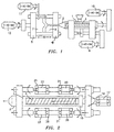
- FIG. 1 shows a prior art all electric injection molding machine, for low tonnage, maximum 300 tons that uses induction-type a-c servomotors (I-AC-SM).
- the injection unit is made of barrel (1), plasticating screw (3) injection nozzle (2).
- Movable platen (5) and fixed platen (4) hold the molds' halves (7,9).
- This machine comprises separate motors for plasticating (10), injection (6), mold opening-closing (12) and parts' ejection (11), each fitted with controls according to the particular function. Since the a-c-servomotors are air cooled, the energy consumption of this machine is very high and with at least four accurate servomotors, the machine is also rather noisy and very expensive.
- FIG. 2 shows a schematic view of a prior art all electric injection unit of a molding machine as disclosed in the U.S. Patent 5,417,558 of Battenfeld.
- the metering drive (15) that turns plasticating screw (3) is powered by a liquid-cooled (19) electric servomotor (17).
- the injection step is achieved by axially moving screw (3) inside and relative to barrel (1), using two drives powered by two similarly liquid-cooled (21) electrical servomotors (20) that operate synchronously.
- the injection nozzle (2) is axially moved relative to barrel (1) by two drives powered by two other similarly liquid-cooled (25) electrical servomotors (23), also operated synchronously.
- this invention does not disclose that the liquid-cooled servomotors have been designed to meet certain sound insulating standards. Considering that there are at least five such motors, the noise level could be very high. This may explain the use of this injection molding machine inside a fully isolated closure.
- the disclosure also fails to teach the power unit and the kind of motors used for the clamp, mold opening-closing or ejection disclosed in the present invention.
- FIG. 3 shows a prior art hydraulic injection molding machine (4) comprising a power pack (25), which comprises a sound insulated metallic closure (24), for generating power.
- the main electrical air cooled motor (EACM) (30) drives the extruder pump EP (34) and the system pump (SP) (32). Both are in hydraulic power connection with power manifold PM (39) that delivers hydraulic power services to the injection unit via injection manifold (IM) (37) and to the clamp unit via clamp manifold (CM) (35).
- the electrical air-cooled motor (EACM) (30) produces noise above the accepted safety standards, i.e. more than 90 dBA.
- metallic closure (24) is further provided with sound absorbing lining (27).
- a battery having more than 4 ventilation fans (29) is attached to metallic closure (24) to improve the motor's cooling system. While this solution lowers the temperature of the motor, it is not sufficient since sound absorbing lining (27) behaves also as a heat insulator. Therefore, inside metallic closure, temperature T2 is still too high and the air humid. The cooler air of temperature T1 provided by electrical fans (29) will become hot air T2 inside metallic closure (24) due to heat produced by motor (30). This hot air is then expelled into the surrounding environment through perforated panel (26), at temperature T3, which is much higher than the air-conditioned temperature T4 in the injection molding plant. Accordingly, the overall air conditioning system of the plastic injection molding plant has to be versatile enough to cope with this additional heat source, requiring increased energy use.
- liquid cooled electrical motors represent a more energy efficient and power supply and considering the shortcomings of prior art injection molding machines regarding power supplies, as discussed above, research and re-design efforts have been put together by the assignee of the present invention to develop an optimal power unit which is both energy and cooling efficient while having a noticeable reduction of noise level.
- liquid-cooled electrical motors are commercially available, they are not known to have been used in conjunction with the hydraulic pumps of an injection molding machine in the manner of the present invention.
- the noise insulating features of electrical motors of the prior art are either non-existent or at least not very effective. Accordingly, such known electrical motors as off-the-shelf equipment cannot be effectively used in an effort to meet the objects of the present invention.
- US-A-5 052 909 discloses a hydraulic injection molding machine according to the preamble of claims 1 and 20.
- WO-A-95 29574 teaches in general the cooling of electric motors of plastic processing machines.
- US-A-5 181 837 discloses a combined electric motor and pump embodied in the same housing and coupled directly with a stationary shaft. The hydraulic fluid is supplied to the interior of the housing and flows to the pump.
- the main object of the present invention is to provide a hydraulic injection molding machine having an improved and simpler sound insulation means.
- Another object of the present invention is to provide a hydraulic injection molding machine that is compact, versatile, and easier to operate, assemble and service.
- Still another object of the present invention is to provide a hydraulic injection molding machine comprising means for quick screw and barrel change.
- Still another object of the present invention is to provide a hydraulic injection molding machine comprising electrical driving means for the hydraulic pumps that saves energy and that is more reliable in long run operations as compared to prior art devices having the same power output.
- Still another object of the present invention is to provide a hydraulic injection molding machine that is safer and environmentally friendlier.
- Yet another object of this invention is to provide an injection molding machine power unit assembly having sound insulated and cooled electric motor meeting and bettering industry standards.
- the present invention discloses an injection molding machine that uses for the first time a liquid cooled electrical motor to power the hydraulic pump that provides services to the injection and/or mold units which motor is cooled and sound insulated for meeting and bettering industry services.
- a liquid cooled electrical motor has been motivated by several criteria, the reduced noise level being the most important one.
- the above innovative power unit for injection molding machines has been designed based on a liquid cooled AC motor which meets the following criteria: (1) reduced noise level, (2) increased energy savings, (3) minimum footprint (floor space), (4) fewer parts, (5) faster assembling-servicing, (6) ecologically friendly and (7) very safe in use.
- FIGS. 4 and 5 a schematic and detailed perspective view, respectively, of an injection molding machine in accordance with the principles of the present invention, designated generally as 110.
- This invention is described in detail with primary reference to injection molding machines by way of an example. However, this invention is also directed to machines in general which require for their operation, cooling and noise reduction units.
- Injection molding machine 110 generally includes an electrical liquid cooled motor (EWCM), preferably water cooled, 112, which is used to drive the hydraulic pumps (128, 130, 140) and power the mechanical moving parts of machine 110, an injection unit 114, a clamp unit 116, and mold 117, a liquid cooled electrical cabinet (WCEC) 118, preferably water cooled, and a coolant 120, preferably water.
- EWCM electrical liquid cooled motor
- WCEC liquid cooled electrical cabinet
- Injection unit 114 is hydraulically powered via an injection manifold (IM) 122 and clamp unit and mold 116 is hydraulically powered via a clamp manifold (CM) 124, wherein injection manifold (IM) 122 and clamp manifold (CM) 124 are hydraulically connected to a power manifold (PM) 126.
- Extruder pump (EP) 128 and system pump (SP) 130 are used to drive the power manifold (PM) 126, all hydraulic, wherein extruder pump (EP) 128 and system pump (SP) 130 are directly electrically connected and controlled by electrical water cooled motor (EWCM) 112.
- EWCM electrical water cooled motor
- a single coolant source (WS) 132 is used to circulate and supply coolant or water 120 for tempering electrical water cooled motor 112, water cooled electrical cabinet 118 and molds of clamp unit and mold 116.
- the coolant is preferably water, other liquids such as oil can also be used as a cooling agent. Water is preferred since it is cleaner, easier to handle and is typically used anyway to cool the mold.
- a cooler (C) 134 is used to maintain coolant 120, as indicated preferably water, at the desired temperature during the operation of injection molding machine 110.
- an oil reservoir 136 is used to supply oil to the hydraulic pumps and a filtering mechanism (F) 138 and a filter pump (FP) 140 are further provided for use with the hydraulic system.
- a controller shown schematically as 142, is provided for use with water cooled electrical cabinet 118 for sending commands to electrical water cooled motor 112 for controlling the rate and amount of cooling therein depending on the operating temperature of the motor, the desired amount of cooling, and the horsepower or size of the motor. Therefore, in accordance with commands from controller 142, the supply of coolant from source 132 to cabinet 118 is increased or decreased.
- injection molding machine 110 includes a quick coupling device for exchanging its plasticating unit, as shown in FIG. 5. This device is described in U.S. Patent 5,011,396, assigned to the assignee of the instant invention.
- electrical water cooled motor 112 preferably comprises a three phase induction motor having a squirrel cage. Preferably only one such motor is used with machine 110.
- Water cooled electrical cabinet 118 is also preferably a steel welded motor frame and comprises a chamber 144 for the circulation therethrough of coolant 120 and for containing coolant 120.
- chamber 144 preferably has a configuration for encircling electric water cooled motor 112, having concentric inner and outer cylindrical walls 146 and 148, respectively, with a space 150 therebetween for the circulation of coolant 120.
- This configuration functions to allow coolant 120 to act also as a sound insulator, for reducing operation noise from the standpoint of the surrounding environment and also function as a heat exchanger, preferably maintaining the operation temperature of motor 112 to less than 40°C.
- Chamber 144 is also preferably plastic coated so as to avoid deterioration thereof. Drain holes (not shown) are provided for insuring proper drainage of any condensed water which may accumulate in chamber 144.
- the size of chamber 144 and the quantity of cooling water circulated therethrough is dependent upon the power of electrical water cooled motor 112.
- controller 142 therefore, shown schematically, automatically increases the amount of coolant and its flow rate, if the temperature increases with respect to a certain threshold value, in order to protect the motor 112 from overheating.
- An inlet 154 and an outlet 156 are provided in water cooled electrical cabinet 118 for the input and output, respectively, of coolant 120 with respect to chamber 144.
- Temperature T4 is indicative of plant temperature and temperature T2 is indicative of the internal temperature of the power unit, including motor 112 and cabinet 118. In accordance with the cooling achieved using the chamber design and motor and cabinet discussed above, T2 substantially equals T4.
- An enclosure can be used to cover motor 112 and the hydraulic pumps that would be necessary only for safety and aesthetic reasons and not for noise reduction or cooling.
- chamber 144 of electrical motor 112 when filled with and configuring a circulating coolant 120 such as water, as shown, is an excellent and innovative sound absorption medium for reducing operating noise, preferably to a prescribed level.
- the particular design of the water chambers and conduits may greatly improve the sound insulation characteristics of the electrical motor. This explains rather large differences among noise levels generated by liquid-cooled motors developed by various manufacturers for cooling but without attention to noise reduction or injection molding machines.
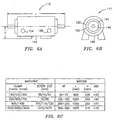
- significant noise insulating improvements have been obtained by the optimum design disclosed herein of the water chambers, with regard to shape, thickness, etc., as indicated in FIG. 6C for motor 112.
- the design described herein meets three major criteria, i.e., (1) improved cooling efficiency, (2) better sound insulation achieved through an optimum size, (3) compact size, preferably having an increased length rather than an increase in diameter for optimum floor space savings.
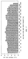
- Figure 7 is a graph indicating the noise generated by a hydraulic injection molding machine powered by water cooled electrical motor 112 in accordance with the principles of the present invention. As can be seen, the sound level measured for such a machine is clearly under and complies with the noise, safety and environmental standards in any country, i.e., the levels are substantially less than 80 dBA.
- the targeted and achieved design criteria for the injection molding machine disclosed in accordance with the principles of the present invention include a maximum noise level under 70dBA applicable for a plurality of variously sized water cooled electrical cabinets 118 for use with a similar variety of motors having a large range of powers and sizes.
- an electrical water cooled motor in accordance with the design standards of the present invention having a power of 373 kW (500 HP) may be required for injection molding machine having a 3650 metric ton clamp, as indicated in FIG. 6C, which machines are generally used in automotive applications.
- the noise level associated with using the design disclosed herein is reduced to equal to or less than 70 dBA, clearly meeting and actually far bettering the noise level standards required by all countries.
- the noise level is reduced to under 67 dBA and for a motor having a power of 111.9 kW (150 HP), the noise level is reduced hereby to under 65 dBA.
- the assignee of the present invention has implemented a "Noise Management Program” that is based on in-house measurements conducted according to the methods contained in Canadian Standards Association (CSA), Standard Z107.56, "Procedures for the Measurement of Occupational Noise Exposure", Clause 6.5 that are compatible with the ISO/DIS 11201-11204.
- the noise level has been measured in various locations in the vicinity of several injection molding machines using a Bruel & Kjaer Type 2236 Precision Integrating Sound Level Meter. This meter has an A-weighting capability, an 80 dB dynamic range, a pulse capability of 83 dB and Type 1 tolerance. At each measurement location the maximum L max. and time weighted average L av.
- noise levels were recorded in dBA.
- short duration measurements were performed for specific noise sources such as the parts' ejectors.
- One third octave band spectra were obtained for these sources from Digital Audio Tape (DAT) recording of the noise sources using a Hewlett Packared 3569, A Real Time Analyzer.
- DAT Digital Audio Tape
- the sound metermicrophone was placed within 0.5 m of an individual's shoulder and the measurements were taken for approximately 10 minute intervals.
- prior art hydraulic injection molding machines disclosed herein comprise a major source of noise, much of which emanates from the water cooled electrical motors that power the hydraulic pump.
- prior art sound insulating devices which were measured, in the form of cabinets for the motors with acoustical insulation or liners have just partially solved this problem by lowering the noise level to up to 85 dBA.
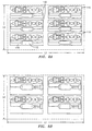
- the state of the art plastic article manufacturing factories can be equipped with a plurality of improved hydraulic injection molding machines 110, as shown in Figure 8A, which machines have a much smaller footprint, as compared to current factories with prior art machines, as shown schematically in Figure 8B, thereby providing the highest output per floor space obtainable while remaining in compliance with stringent noise, temperature, energy and environmental criteria.
- six injection molding machines 110 in accordance with the principles of the present invention may be used as opposed to four for the prior art.
- prior art hydraulic injection molding machines use air cooled motors which are much bigger than the machine 110 disclosed herein having electrical water cooled motor 112.
- the air cooled motors used with the prior art hydraulic injection molding machines are bigger to a degree of 20%, noisier to a degree of 10-15%, and generate heat in the plant and require more electrical energy to a degree of 25-30%, for the same power output.
- only one electrical motor 112 is used to power the hydraulic pumps that form part of the power pack of the hydraulic injection molding machine disclosed herein, and accordingly the machine design herein achieves a high noise insulation level. Since injection unit 114 is operable without any attached motor, a useful arrangement is created since an operator may easily change the plasticating screw (not shown) without interfering with an injection unit motor.
- the main advantage of the present invention is that a hydraulic injection molding machine is provided having an improved and simpler sound insulation means.
- a hydraulic injection molding machine is provided that is compact, versatile and easier to operate, assemble and service.
- a hydraulic injection molding machine is provided comprising means for quick screw and barrel change.
- a hydraulic injection molding machine is provided comprising electrical driving means for the hydraulic pumps that saves energy and that is more reliable in the long run operation for the same output horse power.
- a hydraulic injection molding machine is provided that is safer and environmentally friendlier.
Landscapes
- Engineering & Computer Science (AREA)
- Power Engineering (AREA)
- Manufacturing & Machinery (AREA)
- Mechanical Engineering (AREA)
- Injection Moulding Of Plastics Or The Like (AREA)
- Moulds For Moulding Plastics Or The Like (AREA)
Claims (29)
- Hydraulische Spritzgießmaschine mit:gekennzeichnet durcheiner Einspritzeinheit (114), einer Verschlußeinheit (116) zum Verschließen der Formen (117) und zumindest einer hydraulischen Pumpe (128, 130, 140) zum Antrieb der Einpritz- und Verschlußeinheiten;einem Elektromotor (112) für den Antrieb der zumindest einen Hydraulikpumpe (128, 130, 140), wobei der Elektromotor (112) eine Betriebstemperatur und einen Betriebsgeräuschpegel aufweist;
ein Flüssigkeitsmittel (120) zum Kühlen des Elektromotors (112) und zum Regeln der Betriebstemperatur, wobei das Flüssigkeitsmittel (120) unabhängig von dem gepumpten Hydraulikfluid ist;
ein Mittel zur Aufnahme des Flüssigkeitsmittels (120) nahe dem Elektromotor (112), wobei das Aufnahmemittel ein Mittel zum Anordnen des Flüssigkeitsmittels (120) in einer Konfiguration aufweist, welches die Umgebung durch Dämpfung des Betriebsgeräuschpegels des Elektromotors isoliert; und
einen Verschlußverteiler (124) zum Antrieb der Verschlußeinheit (116) sowie einen Einspritzverteiler (122) zum Antrieb der Einspritzeinheit (114), wobei der flüssigkeitsgekühlte Elektromotor (112) so arbeitet, daß er den Verschlußverteiler (124) und den Einspritzverteiler (122) steuert, und einschließlich eines Energieverteilers (126), der hydraulisch mit dem Verschlußverteiler (124) und dem Einspritzverteiler (122) verbunden ist. - Hydraulische Spritzgießmaschine nach Anspruch 1, bei welcher das Aufnahmemittel einen Schrank (118) zum Einschließen des Elektromotors (112) und des Flüssigkeitsmittels (120) aufweist, wobei das Anordnungsmittel eine Kammer (144) in dem Schrank (118) zum Zirkulieren des Flüssigkeitsmittels (120) aufweist.
- Hydraulische Spritzgießmaschine nach Anspruch 2, die ferner Mittel zum Zirkulieren des Flüssigkeitsmittels (120) durch die Kammer (144) aufweist, um Wärme von dem Elektromotor (112) zum Kühlen des Elektromotors abzuziehen.
- Hydraulische Spritzgießmaschine nach Anspruch 2 oder 3, bei welcher der Schrank (118) zumindest einen Einlaß (154) für den Eintritt des Flüssigkeitsmittels (120) und zumindest einen Auslaß (156) für den Austritt der Flüssigkeitsmittel aufweist.
- Hydraulische Spritzgießmaschine nach einem der Ansprüche 2 bis 4, bei welcher der Schrank (118) einen Wärmeaustauscher aufweist.
- Hydraulische Spritzgießmaschine nach einem der Ansprüche 2 bis 5, bei welcher die Kammer (144) konzentrische innere und äußere zylindrische Wände (146, 148) aufweist, zwischen denen ein Raum (150) für die Zirkulation des Kühlmittels (120) zum Verringern der Betriebstemperatur auf maximal 40°C gebildet ist.
- Hydraulische Spritzgießmaschine nach einem der Ansprüche 1 bis 6, bei welcher das Flüssigkeitsmittel (120) ein Kühlmittel in Form von Wasser ist.
- Hydraulische Spritzgießmaschine nach einem der Ansprüche 1 bis 6, bei welcher das Flüssigkeitsmittel (120) ein Kühlmittel in Form von Öl ist.
- Hydraulische Spritzgießmaschine nach einem der Ansprüche 1 bis 8, bei welcher der Elektromotor (112) ein Dreiphasen-Induktionsmotor ist.
- Hydraulische Spritzgießmaschine nach Anspruch 9, bei welcher der Induktionsmotor (112) einen Käfigläufer aufweist.
- Hydraulische Spritzgießmaschine nach einem der Ansprüche 1 bis 10, bei welcher über das Flüssigkeitsmittel (120) und das Anordnungsmittel der Betriebsgeräuschpegel vom Standpunkt der Umgebung auf einen Maximalpegel von 70 dBA gedämpft wird, für einen Elektromotor (112) mit einer Leistung von höchstens 372 kW (500 PS).
- Hydraulische Spritzgießmaschine nach einem der Ansprüche 1 bis 10, bei welcher über das Flüssigkeitsmittel (120) und das Anordnungsmittel der Betriebsgeräuschpegel vom Standpunkt der Umgebung auf unter 67 dBA gedämpft wird, für einen Elektromotor (112) mit einer Leistung von höchstens 186,5 kW (250 PS).
- Hydraulische Spritzgießmaschine nach einem der Ansprüche 1 bis 10, bei welcher über das Flüssigkeitsmittel (120) und das Anordnungsmittel der Betriebsgeräuschpegel vom Standpunkt der Umgebung unter 65 dBA gedämpft wird, für einen Elektromotor (112) mit einer Leistung von höchstens 111,9 kW (150 PS).
- Hydraulische Spritzgießmaschine nach einem der Ansprüche 1 bis 13, die weiters Mittel zur Steuerung der Temperatur und des Durchsatzes des Flüssigkeitsmittels (120) aufweist.
- Hydraulische Spritzgießmaschine nach Anspruch 14, bei welcher das Steuerungsmittel eine Steuereinrichtung (142) aufweist, welche in dem Aufnahmemittel angeordnet ist.
- Hydraulische Spritzgießmaschine nach einem der Ansprüche 1 bis 15, bei welcher das Anordnungsmittel das Aufnahmemittel aufweist, das eine besondere Form und Ausbildung hat, welche das Flüssigkeitsmittel (120) in dieser Konfiguration hält, wobei das Aufnahmemittel einen Schrank (118) aufweist, und die besondere Form und Ausbildung dieses Schrankes durch eine innere zylindrische Wand (146) nahe dem Elektromotor (112) und eine konzentrische äußere zylindrische Wand (148) gebildet ist, die von der inneren zylindrischen Wand beabstandet ist, wobei die innere zylindrische Wand und die äußere zylindrische Wand eine Kammer (144) definieren, durch welche das Flüssigkeitsmittel (120) strömt.
- Hydraulische Spritzgießmaschine nach einem der Ansprüche 1 bis 16, mit nur einem Elektromotor (112) für die Spritzgießmaschine (110).
- Hydraulische Spritzgießmaschine nach einem der Ansprüche 1 bis 17, die ferner eine Schnellkupplungsvorrichtung zum Entfernen der Plastiziereinheit aufweist.
- Hydraulische Spritzgießmaschine nach einem der Ansprüche 1 bis 18, die ferner eine Quelle (132) für das Flüssigkeitsmittel (120) aufweist.
- Verfahren zum Kühlen und Schallisolieren der Antriebselemente einer hydraulischen Spritzgießmaschine (110), mit einer Einspritzeinheit (114), einer Verschlußeinheit (116) zum Verschließen der Formen (117) und zumindest einer Hydraulikpumpe (128, 130, 140) zum Antrieb der Einspritzund Verschlußeinheiten; einem freistehenden Elektromotor (112) zum Antrieb der zumindest einen Hydraulikpumpe (128, 130, 140), wobei der Elektromotor (112) eine bestimmte Betriebstemperatur und einen Betriebsgeräuschpegel hat;
gekennzeichnet durch
das Vorsehen eines Flüssigkeitsmittels (120) zum Kühlen des Elektromotors (112) und zum Regulieren der Betriebstemperatur, wobei das Flüssigkeitsmittel (120) unabhängig von dem gepumpten Hydraulikfluid ist;
das Vorsehen eines Mittels zur Aufnahme des Flüssigkeitsmittels (120) nahe dem Elektromotor (112), wobei das Aufnahmemittel Anordnungsmittel für das Flüssigkeitsmittel (120) in einer Konfiguration aufweisen, welche die Umgebung durch Dämpfung des Betriebsgeräuschpegels des Elektromotors isoliert;
das Vorsehen eines Verschlußverteilers (124) zum Antrieb der Verschlußeinheit (116) und eines Einspritzverteilers (122) zum Antrieb der Einspritzeinheit (114), wobei der flüssigkeitsgekühlte Elektromotor (112) so arbeitet, daß er den Verschlußverteiler (124) und den Einspritzverteiler (122) steuert, und einen Energieverteiler (126) aufweist, der hydraulisch mit dem Verschlußverteiler (124) und dem Einspritzverteiler (122) in Verbindung steht; und
das Zirkulieren des Flüssigkeitsmittels (120) durch das Aufnahmemittel. - Verfahren nach Anspruch 20, bei welchem das Flüssigkeitsmittel (120) in einem Aufnahmemittel für das Flüssigkeitsmittel (120) angeordnet ist, das dem Elektromotor (112) benachbart ist, wobei das Aufnahmemittel ein Mittel zum Anordnen des Flüssigkeitsmittels (120) in der zum Isolieren bestimmten Konfiguration aufweist.
- Verfahren nach Anspruch 21, bei welchem das Aufnahmemittel einen Schrank (118) zur Aufnahme des Elektromotors (112) und des Flüssigkeitsmittels (120) aufweist, wobei das Anordnungsmittel eine Kammer (144) in dem Schrank (118) zum Zirkulieren des Flüssigkeitsmittels (120) aufweist.
- Verfahren nach Anspruch 22, bei welchem ferner das Flüssigkeitsmittel (120) durch die Kammer (144) zum Abziehen von Wärme von dem Elektromotor (112) zum Kühlen der Antriebselemente zirkuliert wird.
- Verfahren nach Anspruch 22 oder 23, bei welchem der Schrank (118) zumindest einen Einlaß (154) für das Einströmen des Flüssigkeitsmittels (120) und zumindest einen Auslaß (156) für das Ausströmen des Flüssigkeitsmittels aufweist.
- Verfahren nach einem der Ansprüche 22 bis 24, bei welchem die Kammer (144) konzentrische innere und äußere zylindrische Wände (146, 148) aufweist, zwischen denen ein Raum (150) für die Zirkulation des Kühlmittels (120) gebildet ist, um die Betriebstemperatur auf maximal 40°C zu begrenzen.
- Verfahren nach einem der Ansprüche 20 bis 25, bei welchem über das Flüssigkeitsmittel (120) und das Anordnungsmittel der Betriebsgeräuschpegel vom Standpunkt der Umgebung auf maximal 70 dBA gedämpft wird, für einen Elektromotor (112) mit einer Leistung von höchstens 373 kW (500 PS).
- Verfahren nach einem der Ansprüche 20 bis 25, bei welchem über das Flüssigkeitsmittel (120) und das Anordnungsmittel der Betriebsgeräuschpegel vom Standpunkt der Umgebung auf unter einem Pegel von 67 dBA gedämpft wird, für einen Elektromotor (112) mit einer Leistung von höchstens 186,5 kW (250 PS).
- Verfahren nach einem der Ansprüche 20 bis 25, bei welchem das Flüssigkeitsmittel (120) und das Anordnungsmittel der Betriebsgeräuschpegel vom Standpunkt der Umgebung auf unter 65 dBA gedämpft wird, für einen Elektromotor (112) mit einer Leistung von höchstens 111,9 kW (150 PS).
- Verfahren nach einem der Ansprüche 20 bis 28, bei welchem ferner die Temperatur und der Durchsatz des Flüssigkeitsmittels (120) kontrolliert werden.
Applications Claiming Priority (2)
| Application Number | Priority Date | Filing Date | Title |
|---|---|---|---|
| US08/579,049 US5707667A (en) | 1995-12-07 | 1995-12-07 | Sound insulated injection molding machine |
| US579049 | 1995-12-07 |
Publications (3)
| Publication Number | Publication Date |
|---|---|
| EP0778652A2 EP0778652A2 (de) | 1997-06-11 |
| EP0778652A3 EP0778652A3 (de) | 1997-12-10 |
| EP0778652B1 true EP0778652B1 (de) | 2003-11-12 |
Family
ID=24315377
Family Applications (1)
| Application Number | Title | Priority Date | Filing Date |
|---|---|---|---|
| EP96810829A Expired - Lifetime EP0778652B1 (de) | 1995-12-07 | 1996-11-27 | Schall isolierte Spritzgussmaschine |
Country Status (5)
| Country | Link |
|---|---|
| US (1) | US5707667A (de) |
| EP (1) | EP0778652B1 (de) |
| JP (1) | JP2915365B2 (de) |
| AT (1) | ATE254352T1 (de) |
| DE (1) | DE69630655T2 (de) |
Families Citing this family (51)
| Publication number | Priority date | Publication date | Assignee | Title |
|---|---|---|---|---|
| US6077064A (en) * | 1998-09-29 | 2000-06-20 | Husky Injection Molding Systems Ltd. | Injection molding apparatus and method for mounting same |
| US6769901B2 (en) * | 2000-04-12 | 2004-08-03 | Mold-Masters Limited | Injection nozzle system for an injection molding machine |
| CA2358148A1 (en) * | 2001-10-03 | 2003-04-03 | Mold-Masters Limited | A nozzle |
| CA2358187A1 (en) * | 2001-10-03 | 2003-04-03 | Mold-Masters Limited | Nozzle seal |
| US6962492B2 (en) * | 2001-10-05 | 2005-11-08 | Mold-Masters Limited | Gap seal between nozzle components |
| DE10392298B4 (de) * | 2002-02-21 | 2016-04-28 | Mold-Masters (2007) Limited | Spritzgießvorrichtung mit einer Ventilnadelführung für eine ventilbetätigte Düse |
| US7128566B2 (en) * | 2002-02-21 | 2006-10-31 | Mold-Masters Limited | Valve pin guiding tip for a nozzle |
| TWI286874B (en) * | 2002-06-12 | 2007-09-11 | Sumitomo Heavy Industries | Cooling mechanism for cooling electric driving part of injection molding machine and cooling method for the same |
| CN100448646C (zh) * | 2002-07-30 | 2009-01-07 | 标准模具(2007)有限公司 | 用于注塑装置中的热流道的阀针导向和对准系统 |
| US7137807B2 (en) * | 2002-11-21 | 2006-11-21 | Mold-Masters Limited | Hot runner nozzle with a tip, a tip surrounding piece and an alignment piece |
| DE10356937A1 (de) * | 2002-12-09 | 2004-07-15 | Mold-Masters Ltd., Georgetown | Düsenspitze und -dichtung |
| WO2005107029A1 (de) * | 2004-04-03 | 2005-11-10 | Krauss-Maffei Kunststofftechnik Gmbh | Wassergekühlte steuereinrichtung für eine spritzgiessmaschine |
| US9072688B2 (en) | 2008-10-31 | 2015-07-07 | The Invention Science Fund I, Llc | Compositions and methods for therapeutic delivery with frozen particles |
| US20100111834A1 (en) * | 2008-10-31 | 2010-05-06 | Searete Llc, A Limited Liability Corporation Of The State Of Delaware | Compositions and methods for therapeutic delivery with frozen particles |
| US20100111831A1 (en) * | 2008-10-31 | 2010-05-06 | Searete Llc, A Limited Liability Corporation Of The State Of Delaware | Compositions and methods for surface abrasion with frozen particles |
| US9060926B2 (en) | 2008-10-31 | 2015-06-23 | The Invention Science Fund I, Llc | Compositions and methods for therapeutic delivery with frozen particles |
| US8725420B2 (en) * | 2008-10-31 | 2014-05-13 | The Invention Science Fund I, Llc | Compositions and methods for surface abrasion with frozen particles |
| US8603495B2 (en) * | 2008-10-31 | 2013-12-10 | The Invention Science Fund I, Llc | Compositions and methods for biological remodeling with frozen particle compositions |
| US8798932B2 (en) | 2008-10-31 | 2014-08-05 | The Invention Science Fund I, Llc | Frozen compositions and methods for piercing a substrate |
| US9050070B2 (en) * | 2008-10-31 | 2015-06-09 | The Invention Science Fund I, Llc | Compositions and methods for surface abrasion with frozen particles |
| US8788211B2 (en) | 2008-10-31 | 2014-07-22 | The Invention Science Fund I, Llc | Method and system for comparing tissue ablation or abrasion data to data related to administration of a frozen particle composition |
| US8551505B2 (en) * | 2008-10-31 | 2013-10-08 | The Invention Science Fund I, Llc | Compositions and methods for therapeutic delivery with frozen particles |
| US20100111857A1 (en) * | 2008-10-31 | 2010-05-06 | Boyden Edward S | Compositions and methods for surface abrasion with frozen particles |
| US8731841B2 (en) | 2008-10-31 | 2014-05-20 | The Invention Science Fund I, Llc | Compositions and methods for therapeutic delivery with frozen particles |
| US8603494B2 (en) | 2008-10-31 | 2013-12-10 | The Invention Science Fund I, Llc | Compositions and methods for administering compartmentalized frozen particles |
| US20100111836A1 (en) * | 2008-10-31 | 2010-05-06 | Searete Llc, A Limited Liability Corporation Of The State Of Delaware | Compositions and methods for therapeutic delivery with frozen particles |
| US8545857B2 (en) | 2008-10-31 | 2013-10-01 | The Invention Science Fund I, Llc | Compositions and methods for administering compartmentalized frozen particles |
| US20100111835A1 (en) * | 2008-10-31 | 2010-05-06 | Searete Llc, A Limited Liability Corporation Of The State Of Delaware | Compositions and methods for therapeutic delivery with frozen particles |
| US8793075B2 (en) * | 2008-10-31 | 2014-07-29 | The Invention Science Fund I, Llc | Compositions and methods for therapeutic delivery with frozen particles |
| US9050317B2 (en) * | 2008-10-31 | 2015-06-09 | The Invention Science Fund I, Llc | Compositions and methods for therapeutic delivery with frozen particles |
| US8409376B2 (en) * | 2008-10-31 | 2013-04-02 | The Invention Science Fund I, Llc | Compositions and methods for surface abrasion with frozen particles |
| US8721583B2 (en) * | 2008-10-31 | 2014-05-13 | The Invention Science Fund I, Llc | Compositions and methods for surface abrasion with frozen particles |
| US9072799B2 (en) * | 2008-10-31 | 2015-07-07 | The Invention Science Fund I, Llc | Compositions and methods for surface abrasion with frozen particles |
| US8762067B2 (en) * | 2008-10-31 | 2014-06-24 | The Invention Science Fund I, Llc | Methods and systems for ablation or abrasion with frozen particles and comparing tissue surface ablation or abrasion data to clinical outcome data |
| US9050251B2 (en) * | 2008-10-31 | 2015-06-09 | The Invention Science Fund I, Llc | Compositions and methods for delivery of frozen particle adhesives |
| US8485861B2 (en) * | 2008-10-31 | 2013-07-16 | The Invention Science Fund I, Llc | Systems, devices, and methods for making or administering frozen particles |
| US8731840B2 (en) | 2008-10-31 | 2014-05-20 | The Invention Science Fund I, Llc | Compositions and methods for therapeutic delivery with frozen particles |
| US8788212B2 (en) | 2008-10-31 | 2014-07-22 | The Invention Science Fund I, Llc | Compositions and methods for biological remodeling with frozen particle compositions |
| US9060931B2 (en) * | 2008-10-31 | 2015-06-23 | The Invention Science Fund I, Llc | Compositions and methods for delivery of frozen particle adhesives |
| US8545855B2 (en) * | 2008-10-31 | 2013-10-01 | The Invention Science Fund I, Llc | Compositions and methods for surface abrasion with frozen particles |
| US9060934B2 (en) * | 2008-10-31 | 2015-06-23 | The Invention Science Fund I, Llc | Compositions and methods for surface abrasion with frozen particles |
| US20100111841A1 (en) * | 2008-10-31 | 2010-05-06 | Searete Llc | Compositions and methods for surface abrasion with frozen particles |
| DE102012000986B3 (de) * | 2012-01-22 | 2013-05-23 | Arburg Gmbh + Co Kg | Hydraulikeinrichtung mit einer Temperiereinrichtung |
| US20130287885A1 (en) * | 2012-04-27 | 2013-10-31 | Athena Automation Ltd. | Two-platen hybrid injection molding machine |
| DE102014108100A1 (de) * | 2014-06-10 | 2015-12-17 | Dr. Ing. H.C. F. Porsche Aktiengesellschaft | Elektrische Maschine für ein Kraftfahrzeug und Verfahren zum Kühlen einer elektrischen Maschine |
| JP2017140732A (ja) * | 2016-02-09 | 2017-08-17 | 株式会社神戸製鋼所 | 連続押出機 |
| US10574118B2 (en) * | 2016-04-05 | 2020-02-25 | Denso Corporation | Rotating electric machine |
| CN109843846B (zh) | 2016-10-19 | 2022-07-05 | 伊士曼化工公司 | 双环[2.2.2]辛烷的合成 |
| US11518726B2 (en) | 2017-10-11 | 2022-12-06 | Eastman Chemical Company | Synthesis of bicyclo[2.2.2]octane derivatives |
| US10836899B2 (en) | 2018-12-13 | 2020-11-17 | Eastman Chemical Company | Polyesters with specified crystallization half-times |
| CN110524826B (zh) * | 2019-09-06 | 2021-07-06 | 惠州市银新鹏科技有限公司 | 一种减少内应力避免翘曲的塑料注塑设备 |
Citations (2)
| Publication number | Priority date | Publication date | Assignee | Title |
|---|---|---|---|---|
| US5052909A (en) * | 1990-01-19 | 1991-10-01 | Cincinnati Milacron Inc. | Energy-conserving injection molding machine |
| GB2244095A (en) * | 1990-05-17 | 1991-11-20 | Hwang Cheng Luen | Aquarium pump arrangement |
Family Cites Families (12)
| Publication number | Priority date | Publication date | Assignee | Title |
|---|---|---|---|---|
| US3727085A (en) * | 1971-09-30 | 1973-04-10 | Gen Dynamics Corp | Electric motor with facility for liquid cooling |
| US3914630A (en) * | 1973-10-23 | 1975-10-21 | Westinghouse Electric Corp | Heat removal apparatus for dynamoelectric machines |
| JPS60174623A (ja) * | 1984-02-21 | 1985-09-07 | Toshiba Mach Co Ltd | 射出成形機 |
| US4988273A (en) * | 1989-06-23 | 1991-01-29 | Cincinnati Milacron Inc. | Injection molding machines having a brushless DC drive system |
| US4994700A (en) * | 1990-02-15 | 1991-02-19 | Sundstrand Corporation | Dynamoelectric machine oil-cooled stator winding |
| US5011396A (en) | 1990-04-02 | 1991-04-30 | Husky Injection Molding Systems, Ltd. | Quick coupling device for exchanging plasticizing unit of an injection molding machine |
| US5181837A (en) * | 1991-04-18 | 1993-01-26 | Vickers, Incorporated | Electric motor driven inline hydraulic apparatus |
| JPH05103445A (ja) * | 1991-10-05 | 1993-04-23 | Fanuc Ltd | 液冷電動機およびそのジヤケツト |
| ATE157043T1 (de) * | 1992-06-23 | 1997-09-15 | Battenfeld Kunststoffmasch | Spritzaggregat für spritzgiessmaschinen |
| DE4235060C1 (de) * | 1992-10-17 | 1993-12-09 | Hemscheidt Maschtech Schwerin | Antriebseinheit für eine Spritzgießmaschine |
| US5354182A (en) * | 1993-05-17 | 1994-10-11 | Vickers, Incorporated | Unitary electric-motor/hydraulic-pump assembly with noise reduction features |
| US5523640A (en) | 1994-04-22 | 1996-06-04 | Cincinnati Milacron Inc. | Liquid cooling for electrical components of a plastics processing machine |
-
1995
- 1995-12-07 US US08/579,049 patent/US5707667A/en not_active Expired - Lifetime
-
1996
- 1996-11-27 EP EP96810829A patent/EP0778652B1/de not_active Expired - Lifetime
- 1996-11-27 DE DE69630655T patent/DE69630655T2/de not_active Expired - Lifetime
- 1996-11-27 AT AT96810829T patent/ATE254352T1/de active
- 1996-12-09 JP JP8328763A patent/JP2915365B2/ja not_active Expired - Lifetime
Patent Citations (2)
| Publication number | Priority date | Publication date | Assignee | Title |
|---|---|---|---|---|
| US5052909A (en) * | 1990-01-19 | 1991-10-01 | Cincinnati Milacron Inc. | Energy-conserving injection molding machine |
| GB2244095A (en) * | 1990-05-17 | 1991-11-20 | Hwang Cheng Luen | Aquarium pump arrangement |
Also Published As
| Publication number | Publication date |
|---|---|
| DE69630655D1 (de) | 2003-12-18 |
| HK1000061A1 (en) | 2004-05-14 |
| EP0778652A3 (de) | 1997-12-10 |
| JPH09174634A (ja) | 1997-07-08 |
| DE69630655T2 (de) | 2004-10-07 |
| EP0778652A2 (de) | 1997-06-11 |
| US5707667A (en) | 1998-01-13 |
| JP2915365B2 (ja) | 1999-07-05 |
| ATE254352T1 (de) | 2003-11-15 |
Similar Documents
| Publication | Publication Date | Title |
|---|---|---|
| EP0778652B1 (de) | Schall isolierte Spritzgussmaschine | |
| EP0756809B1 (de) | Flüssigkeitskühlsystem für kunststoffverarbeitungsmaschinen | |
| US9267746B2 (en) | Liquid-air cooling system | |
| KR102625998B1 (ko) | 고정자 블록, 고정자 어셈블리 및 고정자 어셈블리의 냉각 시스템 | |
| KR20160124101A (ko) | 전기 모터 및 유압 펌프를 포함하는 컴팩트 유닛 | |
| CN100494699C (zh) | 流体冷却装置 | |
| CN115912794B (zh) | 一种驱动电机主动冷却系统、汽车及方法 | |
| CA2210824C (en) | Sound insulated injection molding machine | |
| HK1000061B (en) | Sound insulated injection molding machine | |
| CN209435018U (zh) | 一种冷却系统、定子组件以及轴向磁场电机 | |
| JP3436345B2 (ja) | 射出成形機の油圧発生装置 | |
| JP6727239B2 (ja) | 回転電機 | |
| US20070163758A1 (en) | Fluid cooling device | |
| CN212033944U (zh) | 油冷机壳以及油冷电机 | |
| US2819415A (en) | Motor bearing cooling | |
| JP2020163835A (ja) | 射出成形機搭載用アクチュエータ、アクチュエータ冷却装置、射出成形機及び、アクチュエータ冷却装置の使用方法 | |
| CN218071238U (zh) | 一种带有冷却功能的新型电机 | |
| JPS61170254A (ja) | 液冷モ−タ | |
| US6008553A (en) | Linear motor with negative pressure cooling circuit | |
| JP4335606B2 (ja) | キャビネット型の給水装置 | |
| JP3864260B2 (ja) | 油圧ユニット一体型油圧シリンダ装置 | |
| KR102112414B1 (ko) | 펌프를 위한 구동 장치 | |
| CN220748676U (zh) | 一种用于热轧机的液压站 | |
| JP2944488B2 (ja) | パッケージ形油冷式空気圧縮機 | |
| CN220113810U (zh) | 用于风力涡轮机叶片的模具的冷却装置和冷却系统 |
Legal Events
| Date | Code | Title | Description |
|---|---|---|---|
| PUAI | Public reference made under article 153(3) epc to a published international application that has entered the european phase |
Free format text: ORIGINAL CODE: 0009012 |
|
| AK | Designated contracting states |
Kind code of ref document: A2 Designated state(s): AT CH DE FR GB IT LI SE |
|
| PUAL | Search report despatched |
Free format text: ORIGINAL CODE: 0009013 |
|
| AK | Designated contracting states |
Kind code of ref document: A3 Designated state(s): AT CH DE FR GB IT LI SE |
|
| 17P | Request for examination filed |
Effective date: 19980121 |
|
| 17Q | First examination report despatched |
Effective date: 19990625 |
|
| TPAD | Observations filed by third parties |
Free format text: ORIGINAL CODE: EPIDOS TIPA |
|
| GRAH | Despatch of communication of intention to grant a patent |
Free format text: ORIGINAL CODE: EPIDOS IGRA |
|
| GRAS | Grant fee paid |
Free format text: ORIGINAL CODE: EPIDOSNIGR3 |
|
| GRAA | (expected) grant |
Free format text: ORIGINAL CODE: 0009210 |
|
| AK | Designated contracting states |
Kind code of ref document: B1 Designated state(s): AT CH DE FR GB IT LI SE |
|
| REG | Reference to a national code |
Ref country code: GB Ref legal event code: FG4D |
|
| REG | Reference to a national code |
Ref country code: CH Ref legal event code: EP |
|
| REF | Corresponds to: |
Ref document number: 69630655 Country of ref document: DE Date of ref document: 20031218 Kind code of ref document: P |
|
| PG25 | Lapsed in a contracting state [announced via postgrant information from national office to epo] |
Ref country code: SE Free format text: LAPSE BECAUSE OF FAILURE TO SUBMIT A TRANSLATION OF THE DESCRIPTION OR TO PAY THE FEE WITHIN THE PRESCRIBED TIME-LIMIT Effective date: 20040212 |
|
| REG | Reference to a national code |
Ref country code: CH Ref legal event code: NV Representative=s name: BOVARD AG PATENTANWAELTE |
|
| ET | Fr: translation filed | ||
| PLBE | No opposition filed within time limit |
Free format text: ORIGINAL CODE: 0009261 |
|
| STAA | Information on the status of an ep patent application or granted ep patent |
Free format text: STATUS: NO OPPOSITION FILED WITHIN TIME LIMIT |
|
| 26N | No opposition filed |
Effective date: 20040813 |
|
| REG | Reference to a national code |
Ref country code: CH Ref legal event code: PFA Owner name: HUSKY INJECTION MOLDING SYSTEMS LTD. Free format text: HUSKY INJECTION MOLDING SYSTEMS LTD.#500 QUEEN STREET SOUTH#BOLTON ONTARIO L7E 5S5 (CA) -TRANSFER TO- HUSKY INJECTION MOLDING SYSTEMS LTD.#500 QUEEN STREET SOUTH#BOLTON ONTARIO L7E 5S5 (CA) |
|
| PGFP | Annual fee paid to national office [announced via postgrant information from national office to epo] |
Ref country code: FR Payment date: 20121004 Year of fee payment: 17 |
|
| PGFP | Annual fee paid to national office [announced via postgrant information from national office to epo] |
Ref country code: GB Payment date: 20121029 Year of fee payment: 17 |
|
| REG | Reference to a national code |
Ref country code: DE Ref legal event code: R082 Ref document number: 69630655 Country of ref document: DE Representative=s name: PATRONUS IP PATENT- & RECHTSANWAELTE BERNHARD , DE Ref country code: DE Ref legal event code: R082 Ref document number: 69630655 Country of ref document: DE Representative=s name: CORINNA VOSSIUS IP GROUP PATENT- UND RECHTSANW, DE |
|
| REG | Reference to a national code |
Ref country code: DE Ref legal event code: R082 Ref document number: 69630655 Country of ref document: DE Representative=s name: CORINNA VOSSIUS IP GROUP PATENT- UND RECHTSANW, DE Ref country code: DE Ref legal event code: R082 Ref document number: 69630655 Country of ref document: DE Representative=s name: PATRONUS IP PATENT- & RECHTSANWAELTE BERNHARD , DE |
|
| REG | Reference to a national code |
Ref country code: DE Ref legal event code: R082 Ref document number: 69630655 Country of ref document: DE Representative=s name: CORINNA VOSSIUS IP GROUP PATENT- UND RECHTSANW, DE |
|
| GBPC | Gb: european patent ceased through non-payment of renewal fee |
Effective date: 20131127 |
|
| REG | Reference to a national code |
Ref country code: FR Ref legal event code: ST Effective date: 20140731 |
|
| PG25 | Lapsed in a contracting state [announced via postgrant information from national office to epo] |
Ref country code: GB Free format text: LAPSE BECAUSE OF NON-PAYMENT OF DUE FEES Effective date: 20131127 Ref country code: FR Free format text: LAPSE BECAUSE OF NON-PAYMENT OF DUE FEES Effective date: 20131202 |
|
| PGFP | Annual fee paid to national office [announced via postgrant information from national office to epo] |
Ref country code: CH Payment date: 20151014 Year of fee payment: 20 Ref country code: IT Payment date: 20151023 Year of fee payment: 20 Ref country code: DE Payment date: 20151015 Year of fee payment: 20 |
|
| PGFP | Annual fee paid to national office [announced via postgrant information from national office to epo] |
Ref country code: AT Payment date: 20151015 Year of fee payment: 20 |
|
| REG | Reference to a national code |
Ref country code: DE Ref legal event code: R071 Ref document number: 69630655 Country of ref document: DE |
|
| REG | Reference to a national code |
Ref country code: CH Ref legal event code: PL |
|
| REG | Reference to a national code |
Ref country code: AT Ref legal event code: MK07 Ref document number: 254352 Country of ref document: AT Kind code of ref document: T Effective date: 20161127 |