EP0778142B1 - Selbstdichtende Fluid-Verbindung - Google Patents
Selbstdichtende Fluid-Verbindung Download PDFInfo
- Publication number
- EP0778142B1 EP0778142B1 EP96305749A EP96305749A EP0778142B1 EP 0778142 B1 EP0778142 B1 EP 0778142B1 EP 96305749 A EP96305749 A EP 96305749A EP 96305749 A EP96305749 A EP 96305749A EP 0778142 B1 EP0778142 B1 EP 0778142B1
- Authority
- EP
- European Patent Office
- Prior art keywords
- assembly
- outlet assembly
- inlet
- sealing
- sealing member
- Prior art date
- Legal status (The legal status is an assumption and is not a legal conclusion. Google has not performed a legal analysis and makes no representation as to the accuracy of the status listed.)
- Expired - Lifetime
Links
Images


Classifications
-
- F—MECHANICAL ENGINEERING; LIGHTING; HEATING; WEAPONS; BLASTING
- F16—ENGINEERING ELEMENTS AND UNITS; GENERAL MEASURES FOR PRODUCING AND MAINTAINING EFFECTIVE FUNCTIONING OF MACHINES OR INSTALLATIONS; THERMAL INSULATION IN GENERAL
- F16L—PIPES; JOINTS OR FITTINGS FOR PIPES; SUPPORTS FOR PIPES, CABLES OR PROTECTIVE TUBING; MEANS FOR THERMAL INSULATION IN GENERAL
- F16L37/00—Couplings of the quick-acting type
- F16L37/28—Couplings of the quick-acting type with fluid cut-off means
- F16L37/30—Couplings of the quick-acting type with fluid cut-off means with fluid cut-off means in each of two pipe-end fittings
- F16L37/32—Couplings of the quick-acting type with fluid cut-off means with fluid cut-off means in each of two pipe-end fittings at least one of two lift valves being opened automatically when the coupling is applied
-
- B—PERFORMING OPERATIONS; TRANSPORTING
- B41—PRINTING; LINING MACHINES; TYPEWRITERS; STAMPS
- B41J—TYPEWRITERS; SELECTIVE PRINTING MECHANISMS, i.e. MECHANISMS PRINTING OTHERWISE THAN FROM A FORME; CORRECTION OF TYPOGRAPHICAL ERRORS
- B41J2/00—Typewriters or selective printing mechanisms characterised by the printing or marking process for which they are designed
- B41J2/005—Typewriters or selective printing mechanisms characterised by the printing or marking process for which they are designed characterised by bringing liquid or particles selectively into contact with a printing material
- B41J2/01—Ink jet
- B41J2/17—Ink jet characterised by ink handling
- B41J2/175—Ink supply systems ; Circuit parts therefor
-
- F—MECHANICAL ENGINEERING; LIGHTING; HEATING; WEAPONS; BLASTING
- F16—ENGINEERING ELEMENTS AND UNITS; GENERAL MEASURES FOR PRODUCING AND MAINTAINING EFFECTIVE FUNCTIONING OF MACHINES OR INSTALLATIONS; THERMAL INSULATION IN GENERAL
- F16L—PIPES; JOINTS OR FITTINGS FOR PIPES; SUPPORTS FOR PIPES, CABLES OR PROTECTIVE TUBING; MEANS FOR THERMAL INSULATION IN GENERAL
- F16L37/00—Couplings of the quick-acting type
- F16L37/28—Couplings of the quick-acting type with fluid cut-off means
Definitions
- This invention relates to a self-sealing fluid interconnect that can be used, for example, to connect an ink supply to an ink-jet printer.
- Ink-jet printers commonly have print heads that are moved over a sheet of paper, or some other material, and selectively eject tiny droplets of ink to form desired characters or images.
- a supply of ink is contained in a reservoir at the print head. This type of ink supply allows for the simple delivery of ink from the reservoir to the print head. However, because the reservoir is moved with the print head, the size of the reservoir may adversely affect printer speed.
- the ink supply is located elsewhere on the printer. This may allow the print head to traverse the paper at a greater speed. However, it also complicates the delivery of ink from the supply to the print head. Generally, in this latter type of printer, the ink is supplied from the reservoir to the print head by a trailing tube.
- ink-jet printers are provided with a docking station into which a replaceable ink supply can be mounted. Upon depletion of the ink supply, it can be extracted easily from the docking station and discarded, and a new ink supply can be inserted.
- a fluid interconnect between the docking station and the ink supply is necessary. Otherwise ink may leak from the ink supply and damage or, at least, impair the function of the printer. It is important that the fluid interconnect provide a tight seal while the ink supply is inserted in the docking station and also that it prevent ink from escaping as the ink supply is uncoupled from the station. Such a fluid interconnect will ensure that little, if any, ink comes in contact with the user.
- the entire ink supply including the fluid interconnect, to be recyclable.
- one fluid interconnect provides a poppet valve on both the printer side and the ink supply side of the fluid interconnect.
- the poppet valve generally has a seat and a metal spring that must be disassembled and removed from the ink supply if the ink supply is to be recycled.
- the fluid interconnect has a valve with a catch on an outlet assembly of an ink supply and compliant fingers on an inlet assembly of a printer.
- the compliant fingers engage the catch upon insertion of the ink supply into the printer.
- the compliant fingers pull the catch to move the valve on the ink supply into a closed position to occlude flow from the ink supply.
- an outlet assembly according to claim 10 is provided.
- a fluid interconnect 9 for connecting an ink supply 28 to a printer station 90 is shown in Fig. 1.
- the illustrated fluid interconnect 9 has an outlet assembly 10 on the ink supply 28 and an inlet assembly 12 connected to the printer station 90.
- the outlet assembly 10 has an actuator 40, a sealing collar 16, and a retaining ring 22.
- the actuator 40 is a hollow tube 14 with a cap 42 on its lower end 74.
- a lateral hole 18 is provided near the lower end 74 to allow ink to flow out of the hollow tube 14.
- the upper end 96 of the hollow tube 14 is in fluid communication with the ink supply 28, and the lower end 74 is exposed for insertion into the inlet assembly 12.
- the actuator 40 is manufactured from polyethylene, but it is envisioned that other materials could also be used.
- the hollow tube 14 slidably fits through a bore 56 in the sealing collar 16.
- the sealing collar 16 has a substantially rigid portion 88 and a compliant portion 86.
- the rigid portion 88 has a primary catch 44 integrally formed therein and extending perpendicular from the axis of the tube 14.
- the compliant portion 86 is sized to provide a friction fit around the tube 14.
- the rigid portion 88 is made of polyethylene, and the compliant portion 86 is made of an elastomer.
- the rigid and compliant portions 88 and 86 are manufactured as a composite by manufacturing the rigid portion 88 and then allowing the compliant portion 86 to flow into the rigid portion 88 and fill in any voids, thereby locking the compliant portion 86 in the rigid portion 88.
- the sealing collar 16 is slidable from a closed position, as shown in Fig. 2, in which the sealing collar 16 covers the lateral hole 18, into an open position, as shown in Fig. 1, in which the lateral hole 18 is exposed.
- the retaining ring 22 is positioned around the tube 14 and the sealing collar 16.
- the retaining ring 22 is ring-shaped.
- guide members of other shapes, such as rectangular projections, could be used instead of the retaining ring 22.
- the retaining ring 22 has an exposed end 46 that is chamfered.
- the retaining ring 22 is provided with a stop 20.
- the stop 20 extends into the interior of the retaining ring 22 in a direction perpendicular to the axis of the retaining ring 22. The stop 20 limits the travel of the sealing collar 16 on the hollow tube 14, as will become clear later.
- the outlet assembly 10 is insertable into the inlet assembly 12.
- the inlet assembly 12 has a fitment 26, a poppet valve 30, and compliant fingers 36.
- the compliant fingers 36 move the sealing collar 16 into a closed position to occlude ink flow through the outlet assembly 10 when the outlet assembly 10 is removed from the inlet assembly 12.
- the fitment 26 of the inlet assembly 12 can be either integrally formed with the printer or attached thereto by, for example, heat-staking or ultrasonic welding.
- the fitment 26 preferably is made from polyethylene.
- the fitment 26 has an inlet aperture 48 extending from the end near the printer to the top exterior 76 of the fitment 26.
- the fitment 26 houses a poppet valve 30.
- the fitment 26 has a concave portion 52 shaped to be flush with the top of the poppet valve 30.
- the fitment 26 is in fluid communication with a trailing tube (not shown) connected to the printer station 90.
- the top exterior 76 of the fitment 26 is provided with a sealing element 24.
- the sealing element 24 has an opening 50 sized to fit the diameter of the hollow tube 14. However, the sealing element 24 could be located on the bottom of the sealing collar 16 rather than on the fitment 26.
- the poppet valve 30 is composed of a seat 32 and a spring 34.
- the spring 34 biases the seat 32 into a closed position against the concave portion 52 of the fitment 26.
- the seat 32 is pressed into an open position by the tube 14 when the outlet assembly 10 is coupled with the inlet assembly 12.
- the seat is polyethylene, and the spring is metal, but various other materials may be used.
- the inlet assembly 12 has two compliant fingers 36 attached to the base 78 of the fitment 26.
- the compliant fingers 36 extend along the outside of the fitment 26 and have hooks 54 that jut radially inward above the top of the fitment 26.
- the compliant fingers 36 may be made of metal, higher modulus plastic, polysulfone, or an equivalent material. As explained more fully below, the compliant fingers 36 move the sealing collar 16 into a closed position when the outlet assembly 10 is extracted from the inlet assembly 12.
- outlet assembly 10 could have a sealing component (not shown) on the exposed face 84 of the sealing collar 16 to ensure a robust seal between the inlet assembly 12 and the outlet assembly 10 before the assemblies 10 and 12 are opened for ink flow.
- the illustrated embodiment shows the outlet assembly 10 on the ink supply and the inlet assembly 12 on the printer; however, the location of the outlet and inlet assemblies 10 and 12 could be reversed.
- the hooks 54 of the compliant fingers 36 press against the chamfered end 46 of the retaining ring 22.
- the elasticity of the compliant fingers 36 allows the compliant fingers 36 to be guided by the chamfered end 46 into the interior 80 of the retaining ring 22.
- the hooks 54 of the compliant fingers 36 engage the primary catch 44 on the sealing collar 16.
- the face 92 of the sealing element 24 of the inlet assembly 12 contacts the bottom of the sealing collar 16.
- the sealing element 24 conforms to the shape of the sealing collar, and a seal is formed between the outlet assembly 10 and the inlet assembly 12. This seal is established before the outlet and inlet assemblies 10 and 12 are opened for ink flow.
- the sealing element 24 pushes the sealing collar 16 from the closed position upward along the tube 14 until the sealing collar 16 hits the stop 20, at which point the lateral hole 18 is exposed within the inlet aperture 48 and ink can flow through the outlet assembly 10 into the inlet assembly 12.
- the lower end 74 of the tube 14 moves the poppet valve 30 to allow ink to flow through the inlet assembly 12.
- the hooks 54 on the compliant fingers 36 pull downward on the primary catch 44 of the sealing collar 16.
- the downward pulling moves the sealing collar 16 from the open position downward along the tube 14 until the walls of the bore 56 in the sealing collar 16 completely cover the lateral hole 18.
- the sealing collar 16 is in the closed position, and ink is prevented from flowing through the outlet assembly 10.
- the compliant fingers 36 and the retaining ring 22 are dimensioned so that once the sealing collar 16 covers the lateral hole 18, the hooks 54 are at the end 46 of the retaining ring 22 and further outward movement of the outlet assembly 10 allows the compliant fingers 36 to spring outward to their free position, thus disengaging the primary catch 44 on the sealing collar 16.
- the sealing collar 16 remains over the lateral hole 18, preventing ink flow through the outlet assembly 10.
- the seal that was formed between the sealing element 24 on the inlet assembly 12 and the sealing collar 16 on the outlet assembly 10 is broken.
- the shape of the inlet assembly 10 and the shape of the outlet assembly 12 generally conform to each other in the region where they join.
- the volume of ink trapped between the outlet and inlet assemblies 10 and 12 is negligible.
- the preferred embodiment of this invention provides a clean disconnect with very little ink released.
- the present invention provides a simple outlet assembly for an ink supply.
- the outlet assembly has a minimum number of parts, and the parts are made of similar materials, thus making the ink supply easy to recycle.
- the outlet assembly of the present invention is closed by the compliant fingers, which are located on the inlet assembly.
- this invention provides a reliable, robust seal for a fluid interconnect.
- the tight seal ensures that little air becomes trapped between the inlet and outlet assemblies when the assemblies are opened for ink flow and likewise ensures that little ink remain between the inlet and outlet assemblies during extraction of the outlet assembly from the inlet assembly.
- little air is ingested during insertion of the outlet assembly into the inlet assembly, and little ink can come in contact with the user or contaminate the printer.
- Figs. 3 and 4 show an alternative embodiment of this invention.
- the outlet assembly of the alternative embodiment 110 has a valve body 58, a projection 60, a sealing member 62, and a retaining ring 122.
- the valve body 58, the projection 60, and the retaining ring 122 are made from polyethylene in the illustrated embodiment.
- the sealing member 62 of the depicted embodiment is made from ethylene-propylene-dimer monomer.
- the valve body 58 is generally a hollow cylindrical member extending outward from the base 98 of the ink supply 28.
- the valve body 58 may be attached to the ink supply 28 by a method such as heat-staking or ultrasonic welding.
- the sealing member 62 is generally disk-shaped with a cylindrical sleeve 68 extending from a location radially inward from the perimeter of the sealing member 62 outwardly along the axis of the sealing member 62 to fit around the bottom portion 82 of the valve body 58.
- the valve body 58 and the sleeve 68 are dimensioned so that friction holds the sleeve 68 in position around the valve body 58 and forms a secure seal to prevent ink from leaking between the two.
- the valve body 58 and the sealing member 62 define a cavity 66 that is in fluid communication with the ink supply 28.
- the sealing member 62 also has a hole 64.
- the projection 60 is attached to the base 98 of the ink supply 28 by heat-staking or ultrasonic welding and extends from the base 98 into the cavity 66.
- the projection is enlarged near its end to form a head 70.
- the head 70 is sized to provide a friction fit inside the hole 64 of the sealing member 62.
- the sealing member 62 When the outlet assembly 110 and the inlet assembly 112 are uncoupled, the sealing member 62 is in a closed position in which the head 70 seals the hole 64 to occlude fluid flow through the outlet assembly 110, as shown in Fig. 3.
- the sealing member 62 slides from the closed position, up the axis of the projection 60 to an open position, as shown in Fig. 4. In the open position, the sealing member 62 no longer surrounds the head 70 but rather surrounds the projection 60, which is narrower than the head 70, thus opening a fluid path from the cavity 66 to the inlet assembly 112.
- the inlet assembly 112 has a sealing element 124 with an opening 150 that is sized to accommodate the head 70 of the projection 60 so that when the head 70 is extended into the opening 150 an annulus exists for flow between the head 70 and sealing element 124.
- the compliant fingers 136 Upon insertion of the outlet assembly 110 into the inlet assembly 112, the compliant fingers 136 are guided by the end 46 of the retaining ring 122 into the interior of the retaining ring 122. The compliant fingers 136 engage the sealing member 62. Simultaneously, the sealing element 124 contacts the face of the sealing member 62 to form a seal between the outlet and inlet assemblies 110 and 112. The sealing element 124 pushes the sealing member 62 along the outside of the valve body 58 until the top of the sleeve 68 abuts the upper interior 100 of the valve body 58. As the sealing member 62 is pushed, the projection 60 presses the seat 32 off the concave portion 52 into the fitment 126. In this position, a fluid path is opened between the ink supply 28, the cavity 66, the hole 64, the opening 150, and the inlet aperture 48, thus allowing ink to flow from the ink supply 28 into the inlet assembly 112.
- the compliant fingers 136 move the sealing member 62 from the open position to the closed position.
- the projection 60 is extracted, causing the spring 34 to force the seat 32 into its closed position.
- the sealing element 124 disengages the sealing member 62, which breaks the seal formed between the outlet and inlet assemblies 110 and 112. Closing the outlet and inlet assemblies 110 and 112 before the seal is broken ensures the only ink that can come in contact with the user is the minimal amount remaining in the annulus.
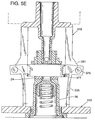
- Figs. 5A-F and 6 show a third alternative embodiment of a self-sealing fluid interconnect, indicated by reference number 309.
- the outlet assembly 310 of the alternative embodiment has an actuator 40, a sealing collar 316, and a guide member 322.
- the hollow tube 14 slidably fits through a bore 356 in the sealing collar 316.
- the sealing collar 316 has a substantially rigid portion 388 and a compliant portion 386.
- the rigid portion 388 has a primary catch 344 and a safety catch 345.
- the primary catch 344 protrudes radially from the center of the exterior walls of the sealing collar 316.
- the safety catch 345 extends radially from the bottom of the exterior walls of the sealing collar 316 and has a larger outer diameter than the primary catch 344.
- the top surfaces 349 and 351 of the primary and safety catches 344 and 345 respectively, slope radially inward at a fifteen degree angle. The sloped top surfaces 349 and 351 help insure that the fingers 336 remain engaged with the top surfaces 349 and 351 while the outlet assembly 310 is extracted from the inlet assembly 312, as will become clear later.
- the sealing collar 316 is slidable from a closed position, as shown in Fig. 5F, in which the sealing collar 316 covers the lateral hole 18 to occlude flow from the outlet assembly 310, into an open position, as shown in Fig. 5A, in which the lateral hole 18 is exposed within the inlet assembly 312 to open a path for fluid flow between the outlet assembly 310 and the inlet assembly 312.
- the guide member 322 is positioned around the tube 14 and the sealing collar 316. As seen in Figs. 5A and 6, the illustrated guide member 322 is frame-shaped with four legs 355 extending downwardly perpendicular to the base of the ink supply 28. The pair of fore legs and the pair of aft legs are each connected by a bridge 357 at the end of the legs 355. Each bridge 357 has a recess 361 with an arcuate stop 353 protruding therein, as best illustrated in Fig. 6. The face of the stop 353 is aligned with the exposed face 384 of the sealing collar 316 so that the stop 353 limits the downward travel of the sealing collar 316 on the hollow tube 14.
- each leg 355 has a cam 363 integrally formed thereon.
- the cam 363 protrudes outward from near the middle of the leg 355 and slopes downwardly to form an upper step 379.
- the bottom of the upper step 379 has a vertical surface 383.
- a lower step 381 protrudes outward and downward from the bottom of the vertical surface of the upper step 379.
- the cam 363 then angles inward to the bridge 357 to form a lower cam surface 377.
- the cam 363 guides the fingers 336 from a disengaged position into an engaged position in which the fingers 336 engage the sealing collar 316, as described in more detail below.
- the outlet assembly 310 is insertable into the inlet assembly 312.
- the inlet assembly 312 has a fitment 26, a poppet valve 30, and compliant fingers 336.
- the compliant fingers 336 move the sealing collar 316 into a closed position to occlude ink flow through the outlet assembly 310.
- the compliant fingers 336 move the sealing collar 316 into the closed position even if the outlet assembly 310 is only partially inserted into the inlet assembly 312.
- the two compliant fingers 336 are attached to a base 378 that surrounds the fitment 26.
- the compliant fingers 336 extend along the outside of the fitment 26 and have a top tooth 365 and a bottom tooth 367.
- the bottom tooth 367 juts inward and downward from the upper region 365 of the finger 336.
- the bottom surface 371 of the bottom tooth 367 extends downward at a fifteen degree angle so as to fit against the top surfaces 349 and 351 of the primary and safety catches 344 and 345.
- the top tooth 365 protrudes from the bottom tooth 367 further inward and also has a bottom surface 373 that slopes at a fifteen degree angle to match the top surfaces 349 and 351.
- the fingers 336 are spring-loaded to urge the fingers 336 inward toward the fitment 26.
- the fingers 336 have rectangular extensions 397 protruding from the upper region 369 in an opposite direction as that of the top and bottom teeth 365 and 367.
- the rectangular extensions 397 have a cam follower 375.
- the cam follower 375 is composed of two cylinders, each having an axis extending perpendicular from the sides of the fingers 336; although other shapes could be used for cam followers.
- the cam follower 375 rides along the cam 363 to guide the fingers 336 from the disengaged position to the engaged position, as will become clear below.
- the sealing collar 316 and the seat 32 are in the closed position, as shown in Fig. 5F.
- the cam follower 375 on the finger 336 contacts the lower cam surface 377.
- the cam follower 375 rides upward and outward along the lower cam surface 377, causing the finger 336 to deflect outward also, as shown in Fig 5E.
- the cam follower 375 rides up the vertical surface 383, and the top tooth 365 disengages the safety catch 345.
- the seal 24 begins to move the sealing collar 316 upward along the hollow tube 14 to begin to uncover the hole 18, and the tube 14 begins to unseat the seat 32, as shown in Fig. 5B.
- the outlet assembly 310 is partially inserted into the inlet assembly 312.
- the tip 387 of the top tooth 365 rides along the exterior wall of the primary catch 344 and the cam follower 375 is not in contact with the guide member 322.
- the guide member 322 and the hollow tube 14 move upward relative to the inlet assembly 312.
- the fingers 336 remain stationary and because the top and bottom teeth 365 and 367 are engaged with the primary and safety catches 344 and 345, the top and bottom teeth 365 and 367 exert pressure on the primary and safety catches 344 and 345, forcing the sealing collar 316 to remain in place as the hollow tube 14 is moved upward.
- the bottom surface 373 of the top tooth 365 momentarily engages the top surface 351 of the safety catch 345 before the lower step 381 engages the cam follower 375 and thereby deflects the fingers 336 further outward.
- the fingers 336 are now fully disengaged from the sealing collar 316.
- the cam follower 375 follows the lower cam surface 377 until the outlet assembly 310 is fully disengaged from the inlet assembly 312.
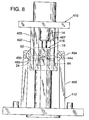
- FIG. 7 A fourth embodiment of a self-sealing fluid interconnect is shown in Fig. 7 as reference number 409.
- the inlet assembly 412 has two safety fingers 465 and two primary fingers 467.
- the outlet assembly 410 has a sealing collar 416 with one catch, a primary catch 444.
- the outlet assembly 410 also has a guide member 422 with four "U"-shaped members 491.
- the legs 455 of the "U"-shaped member 491 are positioned so that when the inlet assembly 412 is inserted into the outlet assembly 410, the safety and primary fingers 465 and 467 fit in the space between the two legs 455 of each "U"-shaped member 491.
- Each leg adjacent to a safety finger 465 has a safety cam 463; likewise, each leg adjacent to a primary finger 467 has a primary cam 461.
- the safety and primary cams 463 and 461 are trapezoidal-shaped and extend outward from the corresponding legs 455.
- each of the safety fingers 465 has two safety cam followers 494 protruding therefrom.
- the upper sides 483 of each of the primary fingers 467 also have two primary cam followers 493 protruding therefrom.
- the protruding portion of the safety and primary cam followers 494 and 493 are semi-oval shaped.
- the safety cam followers 494 on the safety fingers 465 engage the lower surfaces of the safety cams 463, causing the safety fingers 465 to be deflected outward.
- the safety cam followers 494 ride along the vertical surface of the safety cams 463 and then along the upper surface of the safety cams 463.
- the safety fingers 465 spring inward, and when the safety cam followers 494 reach the outer vertical surface of the legs 487 the tooth 495 engages the primary catch 444.
- the face 92 of the seal 24 has not mated with the exposed face 84 of the sealing collar 416, as can be seen in Fig. 8.
- the outlet assembly 410 is further inserted from the partially connected position to the fully connected position. As this occurs, the face 92 of the seal 24 will continue to press on the exposed face 84 of the sealing collar 416 to further push the sealing collar 416 upward along the hollow tube 14.
- the primary cam follower 493 rides over the primary cam 461.
- the sealing collar 416 reaches the ridge 497 on the hollow tube 14, which limits the upward travel of the sealing collar 416, as shown in Fig. 7.
- the seal 24 compresses, and thus the primary fingers 467 disengage and move upward relative to the sealing collar 416.
- the primary fingers 467 spring inward to engage the primary catch 444, as shown in Fig. 7.
- the teeth 495 on the primary fingers 467 will keep the sealing collar 416 stationary as the hollow tube 14 is moved upward.
- the primary cam followers 493 on the primary fingers 467 contact the top surface of the primary cams 461, thereby being deflected outward to release the primary catch 444 on the sealing collar 416.
- the sealing collar 416 is left in the closed position.
- the teeth 495 on the safety fingers 465 will momentarily contact the primary catch 444 before the safety fingers are guided by the safety cams 463 to disengage the sealing collar 416. The momentary contact will not move the sealing collar 416, at least not significantly.
- a fifth alternative embodiment of a fluid interconnect 509 is shown in Fig. 9.
- the fluid interconnect 509 has an outlet assembly 510, like outlet assembly 10 of the embodiment illustrated in Figs. 1 and 2 but without a retaining ring 22.
- the fluid interconnect 509 also has an inlet assembly 512 like inlet assembly 12 but without the fingers 36.
- the outlet valve 510 can function only once.
- the outlet and inlet assemblies 510 and 512 are opened in the same manner as the outlet and inlet assemblies 10 and 12 of the preferred embodiment.
- the sealing collar 516 is not moved back to the closed position. Rather, the sealing collar 516 remains open and the ink supply 28 must be discarded after one use.
- This embodiment is advantageous because it is simple and easy to recycle.
- a sixth embodiment of a fluid interconnect of the present invention is illustrated in Fig. 10 as reference number 609.
- the fluid interconnect 609 is essentially the fluid interconnect of Figs. 3 and 4 without fingers and a retaining ring. This fluid interconnect 609 would be for one-time use and would function the same way as the fluid interconnect 509.
Claims (10)
- Eine Fluidverbindung zum Verbinden einer Tintenversorgung mit einem Tintenstrahldrucker, wobei die Fluidverbindung folgende Merkmale aufweist:eine Auslaßanordnung (10, 110), die ein Dichtungsbauglied (16, 62), das zwischen einer ersten Stellung zum Verschließen eines Fluidflusses durch die Auslaßanordnung und einer zweiten Stellung zum Ermöglichen eines Fluidflusses durch die Auslaßanordnung bewegbar ist, eine primäre Eingriffeinrichtung (44), die an dem Dichtungsbauglied befestigt ist, ein Betätigungsglied (14, 60), das dem Dichtungsbauglied zugeordnet ist, und ein Führungsbauglied (22, 122) benachbart zu zumindest einem Abschnitt des Dichtungsbauglieds aufweist; undeine Einlaßanordnung (12, 112) zum Koppeln mit der Auslaßanordnung, wobei die Einlaßanordnung ein Anschlußstück (26) mit einer Einlaßöffnung (48), einen Sitz (32), der in dem Anschlußstück aus einer geschlossenen Stellung, in der der Sitz einen Fluidfluß durch die Einlaßöffnung verschließt, in eine offene Stellung, in der der Sitz den Fluidfluß durch die Einlaßöffnung nicht verschließt, bewegbar ist, wobei der Sitz zu der geschlossenen Stellung hin vorgespannt und durch das Betätigungsglied in die offene Stellung bewegbar ist, wenn die Auslaßanordnung mit der Einlaßanordnung gekoppelt ist, um einen Fluidfluß von der Auslaßanordnung in die Einlaßanordnung zu ermöglichen, und einen nachgebenden Finger (36) aufweist, der zwischen einer In-Eingriff-Stellung, in der der nachgebende Finger die primäre Eingriffeinrichtung in Eingriff nimmt, und einer Außer-Eingriff-Stellung bewegbar ist, wobei der nachgebende Finger derart positioniert ist, daß das Führungsbauglied den nachgebenden Finger aus der Außer-Eingriff-Stellung in die In-Eingriff-Stellung ablenkt, wenn die Auslaßanordnung mit der Einlaßanordnung gekoppelt wird, und derart, daß der nachgebende Finger das Dichtungsbauglied aus der zweiten Stellung in die erste Stellung bewegt, wenn die Einlaßanordnung von der Auslaßanordnung abgekoppelt wird.
- Die Fluidverbindung nach Anspruch 1, bei der die Auslaßanordnung (10) eine hohle Röhre (14) aufweist, wobei die hohle Röhre ein oberes Ende (96) in Fluidverbindung mit einer Tintenversorgung (28), ein geschlossenes unteres Ende (74) und ein laterales Loch (18) besitzt, wobei das Dichtungsbauglied (16) derart auf der hohlen Röhre positioniert ist, daß das Dichtungsbauglied in der ersten Stellung das laterale Loch abdeckt, um den Fluß von Tinte durch die Röhre zu verhindern, und wobei das untere Ende der hohlen Röhre das Betätigungsglied (14) ist.
- Die Fluidverbindung nach Anspruch 1, bei der die Auslaßanordnung (110) ferner folgende Merkmale aufweist:einen Ventilkörper (58), der einen Hohlraum (66) in Fluidverbindung mit einer Tintenversorgung (28) definiert;einen Vorsprung (60), der sich von dem Hohlraum erstreckt, wobei der Vorsprung das Betätigungsglied (60) ist; undbei der das Dichtungsbauglied (62) eine Öffnung (64) zum Aufnehmen des Vorsprungs aufweist, wobei das Dichtungsbauglied den Hohlraum einhüllt und die Öffnung definiert, die in der ersten Stellung durch den Vorsprung abgedichtet ist und in der zweiten Stellung den Fluß von Tinte aus dem Hohlraum ermöglicht.
- Die Fluidverbindung nach Anspruch 1, bei der die primäre Eingriffeinrichtung (44) eine geneigte Oberfläche (349, 351) aufweist, und bei der der Finger (336) eine geneigte Oberfläche aufweist, um die geneigte Oberfläche auf der Eingriffeinrichtung in Eingriff zu nehmen.
- Die Fluidverbindung nach Anspruch 1, bei der das Führungsbauglied (322) eine Nocke (366) zum Führen des Fingers (336) in die In-Eingriff-Stellung aufweist.
- Die Fluidverbindung nach Anspruch 1, bei der das Führungsbauglied (322) eine Nocke (363) zum Führen des Fingers (336) aus der In-Eingriff-Stellung aufweist, wodurch das Dichtungsbauglied in der ersten Stellung belassen wird.
- Die Fluidverbindung nach Anspruch 1, die ferner einen Mechanismus (336) aufweist, um das Dichtungsbauglied (16, 62) aus einer Stellung, in der die Auslaßanordnung (10, 110) teilweise mit der Einlaßanordnung (12, 112) gekoppelt ist, in die erste Stellung zu bewegen, während die Auslaßanordnung von der Einlaßanordnung abgekoppelt wird.
- Die Fluidverbindung nach Anspruch 7, bei der der Mechanismus folgende Merkmale aufweist:eine Sicherheitseingriffeinrichtung (345), die an dem Dichtungsbauglied befestigt ist;einen ersten Zahn (365), der an dem Finger befestigt ist; undeinen zweiten Zahn (367), der an dem Finger befestigt ist; undwobei der erste Zahn zum Eingreifen in die Sicherheitseingriffeinrichtung dient, um das Dichtungsbauglied (316) aus der teilweise gekoppelten Stellung in die erste Stellung zu bewegen, während die Auslaßanordnung (310) von der Einlaßanordnung (312) abgekoppelt wird.
- Die Fluidverbindung nach Anspruch 7, bei der der Mechanismus einen zweiten Finger aufweist, der positioniert ist, um die primäre Eingriffeinrichtung in Eingriff zu nehmen, wenn die Auslaßanordnung teilweise mit der Einlaßanordnung gekoppelt ist, und um das Dichtungsbauglied aus der teilweise gekoppelten Stellung in die erste Stellung zu bewegen, während die Auslaßanordnung von der Einlaßanordnung abgekoppelt wird.
- Eine Auslaßanordnung für eine Tintenversorgung, die mit einer Einlaßanordnung an einem Tintenstrahldrucker, der einen nachgebenden Finger aufweist, verbindbar ist, wobei die Auslaßanordnung folgende Merkmale aufweist:eine hohle Röhre (14) mit einem oberen Ende (96) in Fluidverbindung mit der Tintenversorgung (28), einem geschlossenen unteren Ende (74) und einem lateralen Loch (18);eine Dichtungsmanschette (16), die auf der hohlen Röhre (14) positioniert und aus einer ersten Stellung, in der die Dichtungsmanschette das laterale Loch bedeckt, um einen Tintenfluß durch die Auslaßanordnung (10) zu verhindern, in eine zweite Stellung, in der Dichtungsmanschette das laterale Loch nicht bedeckt, bewegbar ist;eine primäre Eingriffeinrichtung (44), die an der Dichtungsmanschette befestigt ist; undein Führungsbauglied (22), das benachbart zu zumindest einem Abschnitt der Dichtungsmanschette positioniert ist, wobei das Führungsbauglied den nachgebenden Finger (36) führt, um die primäre Eingriffeinrichtung auf das Einbringen der Tintenversorgung in die Einlaßanordnung (12) hin derart in Eingriff zu nehmen, daß, wenn die Tintenversorgung aus der Einlaßanordnung an dem Drucker gezogen wird, der nachgebende Finger die Dichtungsmanschette in die erste Stellung zurückbringt.
Applications Claiming Priority (2)
| Application Number | Priority Date | Filing Date | Title |
|---|---|---|---|
| US566986 | 1995-12-04 | ||
| US08/566,986 US5796419A (en) | 1995-12-04 | 1995-12-04 | Self-sealing fluid interconnect |
Publications (2)
| Publication Number | Publication Date |
|---|---|
| EP0778142A1 EP0778142A1 (de) | 1997-06-11 |
| EP0778142B1 true EP0778142B1 (de) | 1999-05-26 |
Family
ID=24265288
Family Applications (1)
| Application Number | Title | Priority Date | Filing Date |
|---|---|---|---|
| EP96305749A Expired - Lifetime EP0778142B1 (de) | 1995-12-04 | 1996-08-05 | Selbstdichtende Fluid-Verbindung |
Country Status (4)
| Country | Link |
|---|---|
| US (1) | US5796419A (de) |
| EP (1) | EP0778142B1 (de) |
| JP (1) | JP3016740B2 (de) |
| DE (1) | DE69602576T2 (de) |
Cited By (2)
| Publication number | Priority date | Publication date | Assignee | Title |
|---|---|---|---|---|
| CN106256549A (zh) * | 2015-06-26 | 2016-12-28 | 珠海市墨的数码科技有限公司 | 一种灌墨系统 |
| US11090934B2 (en) | 2017-08-31 | 2021-08-17 | Hewlett-Packard Development Company, L.P. | Print fluid manifold |
Families Citing this family (46)
| Publication number | Priority date | Publication date | Assignee | Title |
|---|---|---|---|---|
| JPH08174860A (ja) * | 1994-10-26 | 1996-07-09 | Seiko Epson Corp | インクジェットプリンタ用インクカートリッジ |
| US6382589B1 (en) * | 1996-02-14 | 2002-05-07 | Edstrom Industries, Inc. | Latch mechanism and quick-connect coupling usable with automatic water docking system for cage and rack systems |
| EP0827836B1 (de) | 1996-02-21 | 2005-05-04 | Seiko Epson Corporation | Tintenkartusche |
| US6113229A (en) * | 1996-10-07 | 2000-09-05 | Hewlett-Packard Company | Interchangeable fluid interconnect attachment and interface |
| KR100209516B1 (ko) * | 1997-02-05 | 1999-07-15 | 윤종용 | 잉크젯 프린트 헤드의 잉크 저장 장치 및 방법 |
| JP4141523B2 (ja) | 1997-03-19 | 2008-08-27 | セイコーエプソン株式会社 | インク供給流路の弁装置 |
| EP1281526B1 (de) * | 1998-02-13 | 2005-09-14 | Seiko Epson Corporation | Verfahren zur Wiederherstellung der Tintenstrahltropfenausstossfähigkeit |
| DE69943172D1 (de) * | 1998-07-15 | 2011-03-10 | Seiko Epson Corp | Tintenbehälter |
| US6299132B1 (en) * | 1999-03-31 | 2001-10-09 | Halkey-Roberts Corporation | Reflux valve |
| WO2001007321A1 (en) * | 1999-07-23 | 2001-02-01 | Scholle Corporation | Connector assembly for fluid flow with rotary motion for connection and disconnection |
| US6644367B1 (en) | 1999-07-23 | 2003-11-11 | Scholle Corporation | Connector assembly for fluid flow with rotary motion for connection and disconnection |
| US6394503B1 (en) | 2000-03-23 | 2002-05-28 | Lexmark International, Inc. | System for securing tubing |
| PT1199179E (pt) * | 2000-10-20 | 2007-02-28 | Seiko Epson Kabushiki Kaisha S | Dispositivo de gravação a jacto de tinta e cartucho de tinta |
| ES2276199T3 (es) * | 2000-10-20 | 2007-06-16 | Seiko Epson Corporation | Un dispositivo de registro de inyeccion de tinta y cartucho de tinta. |
| EP1199178B1 (de) * | 2000-10-20 | 2008-06-11 | Seiko Epson Corporation | Tintenpatrone für Tintenstrahlaufzeichnungsgerät |
| NL1018564C2 (nl) | 2001-07-17 | 2003-01-20 | Oce Tech Bv | Een inrichting voor het transporteren van vloeibare inkt, een flexibele slang geschikt voor een dergelijke inrichting en het gebruik van een dergelijke slang. |
| FR2837421B1 (fr) * | 2002-03-22 | 2004-07-02 | Imaje Sa | Raccord hydro-electrique pour tete d'imprimante et imprimante equipee |
| US6948801B2 (en) * | 2002-04-04 | 2005-09-27 | Hewlett-Packard Development Company, L.P. | Fluid interconnect with sealant |
| JP3804576B2 (ja) * | 2002-05-13 | 2006-08-02 | ソニー株式会社 | 液体供給装置及び液体吐出装置 |
| JP3991853B2 (ja) * | 2002-09-12 | 2007-10-17 | セイコーエプソン株式会社 | インクカートリッジ |
| US20080009822A1 (en) * | 2003-12-18 | 2008-01-10 | Halkey-Roberts Corporation | Needleless access vial |
| US7281785B2 (en) * | 2004-09-17 | 2007-10-16 | Fujifilm Dimatix, Inc. | Fluid handling in droplet deposition systems |
| TWI343323B (en) * | 2004-12-17 | 2011-06-11 | Fujifilm Dimatix Inc | Printhead module |
| US7556364B2 (en) * | 2005-12-05 | 2009-07-07 | Silverbrook Research Pty Ltd | Ink cartridge with self sealing outlet valve |
| US7357496B2 (en) * | 2005-12-05 | 2008-04-15 | Silverbrook Research Pty Ltd | Inkjet printhead assembly with resilient ink connectors |
| US7467863B2 (en) * | 2005-12-05 | 2008-12-23 | Silverbrook Research Pty Ltd | Inkjet printer with disengageable maintenance station drive coupling |
| US7721441B2 (en) * | 2006-03-03 | 2010-05-25 | Silverbrook Research Pty Ltd | Method of fabricating a printhead integrated circuit attachment film |
| US7837297B2 (en) | 2006-03-03 | 2010-11-23 | Silverbrook Research Pty Ltd | Printhead with non-priming cavities for pulse damping |
| EP1991422B1 (de) * | 2006-03-03 | 2012-06-27 | Silverbrook Research Pty. Ltd | Impulsgedämpfte fluidarchitektur |
| US8523143B2 (en) * | 2007-03-21 | 2013-09-03 | Zamtec Ltd | Detachable fluid coupling for inkjet printer |
| US7654640B2 (en) * | 2007-03-21 | 2010-02-02 | Silverbrook Research Pty Ltd | Printhead with drive circuitry components adjacent the printhead IC |
| US7758177B2 (en) * | 2007-03-21 | 2010-07-20 | Silverbrook Research Pty Ltd | High flowrate filter for inkjet printhead |
| US20080231660A1 (en) * | 2007-03-21 | 2008-09-25 | Silverbrook Research Pty Ltd | Printhead with ink conduit weir for priming control |
| US7780278B2 (en) * | 2007-03-21 | 2010-08-24 | Silverbrook Research Pty Ltd | Ink coupling for inkjet printer with cartridge |
| US20120033019A1 (en) * | 2010-08-09 | 2012-02-09 | Toshiba Tec Kabushiki Kaisha | Inkjet recording apparatus and inkjet recording method |
| US20120267393A1 (en) * | 2011-04-21 | 2012-10-25 | Fres-Co System Usa, Inc. | Fitment and pouch for connection to a probe and pump-out metering system |
| FR2997683B1 (fr) * | 2012-11-06 | 2015-01-16 | Oreal | Dispositif mere fille a pompe |
| US10104867B2 (en) * | 2013-03-15 | 2018-10-23 | Hydropac/Lab Products, Inc. | Automatic fluid Delivery systems and methods |
| JP6183455B2 (ja) * | 2013-03-29 | 2017-08-23 | コニカミノルタ株式会社 | 画像形成装置 |
| EP3152058B1 (de) | 2014-06-05 | 2018-12-19 | Videojet Technologies Inc. | Sensoranordnung für tintenaufbau |
| JP6768523B2 (ja) | 2014-06-05 | 2020-10-14 | ヴィデオジェット テクノロジーズ インコーポレイテッド | 連続インクジェットプリンター用のフィルターモジュール及び連続インクジェットプリンター |
| WO2015187983A2 (en) | 2014-06-05 | 2015-12-10 | Videojet Technologies Inc. | Continuous ink jet print head with zero adjustment embedded charging electrode |
| FR3034345B1 (fr) | 2015-04-02 | 2019-08-23 | Dover Europe Sarl | Connecteur configurable |
| GB2539053A (en) * | 2015-06-05 | 2016-12-07 | Dimmer Paul | 2 way non return isolation valve |
| EP3359382B1 (de) * | 2015-10-08 | 2020-06-17 | Sicpa Holding Sa | Sicheres nachfüllsystem |
| DE202019004683U1 (de) * | 2019-11-19 | 2021-02-22 | Volkmann Gmbh | Andockvorrichtung, Ventilvorrichtung und Dosiervorrichtung sowie Behälter damit |
Family Cites Families (12)
| Publication number | Priority date | Publication date | Assignee | Title |
|---|---|---|---|---|
| US2024682A (en) * | 1933-09-15 | 1935-12-17 | Arthur A Eisenman | Quick detachable hose coupling |
| US2412685A (en) * | 1944-04-22 | 1946-12-17 | Linde Air Prod Co | Conduit coupling |
| US2411057A (en) * | 1945-07-02 | 1946-11-12 | James S Robbins | Hose coupling |
| GB829531A (en) * | 1958-07-04 | 1960-03-02 | John B Pillin Ltd | Improvements in or relating to couplings for connecting pipelines to sources of fluid pressure |
| DE1808164U (de) * | 1958-10-23 | 1960-03-17 | K A C Ltd | Selbstdichtende kupplung fuer stroemungsmittelleitungen. |
| BE723669A (de) * | 1968-08-30 | 1969-04-16 | ||
| US4114853A (en) * | 1976-10-08 | 1978-09-19 | Swagelok Company | Quick connect coupling |
| DE3003398A1 (de) * | 1979-02-02 | 1980-08-07 | Sperry Corp | Kupplung fuer fluessige oder gasfoermige medien |
| DE3137969A1 (de) * | 1981-09-24 | 1983-03-31 | Olympia Werke Ag, 2940 Wilhelmshaven | Kupplung zum leckfreien verbinden gas- oder fluessigkeitsgefuellter rohre und behaelter |
| DE3446998A1 (de) * | 1983-12-26 | 1985-07-04 | Canon K.K., Tokio/Tokyo | Tintenstrahl-aufzeichnungsgeraet |
| US5606988A (en) * | 1994-02-04 | 1997-03-04 | Hewlett -Packard Company | Connector assembly for ink cartridge |
| US5544858A (en) * | 1995-07-26 | 1996-08-13 | Aeroquip Corporation | Quick disconnect fluid coupling |
-
1995
- 1995-12-04 US US08/566,986 patent/US5796419A/en not_active Expired - Fee Related
-
1996
- 1996-08-05 DE DE69602576T patent/DE69602576T2/de not_active Expired - Fee Related
- 1996-08-05 EP EP96305749A patent/EP0778142B1/de not_active Expired - Lifetime
- 1996-11-28 JP JP8332876A patent/JP3016740B2/ja not_active Expired - Fee Related
Cited By (3)
| Publication number | Priority date | Publication date | Assignee | Title |
|---|---|---|---|---|
| CN106256549A (zh) * | 2015-06-26 | 2016-12-28 | 珠海市墨的数码科技有限公司 | 一种灌墨系统 |
| CN106256549B (zh) * | 2015-06-26 | 2018-11-13 | 珠海市墨的数码科技有限公司 | 一种灌墨系统 |
| US11090934B2 (en) | 2017-08-31 | 2021-08-17 | Hewlett-Packard Development Company, L.P. | Print fluid manifold |
Also Published As
| Publication number | Publication date |
|---|---|
| EP0778142A1 (de) | 1997-06-11 |
| US5796419A (en) | 1998-08-18 |
| JPH09187959A (ja) | 1997-07-22 |
| DE69602576D1 (de) | 1999-07-01 |
| DE69602576T2 (de) | 1999-09-23 |
| JP3016740B2 (ja) | 2000-03-06 |
Similar Documents
| Publication | Publication Date | Title |
|---|---|---|
| EP0778142B1 (de) | Selbstdichtende Fluid-Verbindung | |
| EP0666176B1 (de) | Verbinderanordnung für Farbstoffpatrone | |
| EP1122076B1 (de) | Auswechselbarer Tintenbehälter mit abnehmbarem Klinkenhebel | |
| EP0722837B1 (de) | Ventil für Tintenbehälter | |
| US5878798A (en) | Valve system | |
| CA2412569C (en) | Ink cartridge | |
| US7328987B2 (en) | Ink cartridge and inkjet printer | |
| JP3411270B2 (ja) | 流体連通用の連結部材 | |
| DK2588320T3 (en) | Fluidpatron | |
| US6299296B2 (en) | Sealing member for a fluid container | |
| EP1701848B1 (de) | System und verfahren zur verbindung einer tintenflasche mit einem tintenreservoir eines tintenstrahldrucksystems | |
| EP0687846B1 (de) | Schnellkupplungseinheit mit balg und geringer leckrate | |
| JPH09187967A (ja) | インクジェット・ペン用の流体相互接続部 | |
| EP1674270B1 (de) | Tintenpatrone | |
| MX2007013369A (es) | Componente de sellado que define un primer, un segundo y un tercer sello. | |
| EP3191309B1 (de) | Druckkopfanordnung | |
| JP4813760B2 (ja) | インクカートリッジ | |
| JP3928312B2 (ja) | インクジェット記録装置 | |
| EP4159448A1 (de) | Tintennachfüllbehälter | |
| JP2006027195A (ja) | 液体収容容器、液体収容容器の液体供給機構、及び液体噴射装置 |
Legal Events
| Date | Code | Title | Description |
|---|---|---|---|
| PUAI | Public reference made under article 153(3) epc to a published international application that has entered the european phase |
Free format text: ORIGINAL CODE: 0009012 |
|
| AK | Designated contracting states |
Kind code of ref document: A1 Designated state(s): DE FR GB IT |
|
| 17P | Request for examination filed |
Effective date: 19970806 |
|
| GRAG | Despatch of communication of intention to grant |
Free format text: ORIGINAL CODE: EPIDOS AGRA |
|
| 17Q | First examination report despatched |
Effective date: 19980917 |
|
| GRAG | Despatch of communication of intention to grant |
Free format text: ORIGINAL CODE: EPIDOS AGRA |
|
| GRAH | Despatch of communication of intention to grant a patent |
Free format text: ORIGINAL CODE: EPIDOS IGRA |
|
| GRAH | Despatch of communication of intention to grant a patent |
Free format text: ORIGINAL CODE: EPIDOS IGRA |
|
| GRAA | (expected) grant |
Free format text: ORIGINAL CODE: 0009210 |
|
| AK | Designated contracting states |
Kind code of ref document: B1 Designated state(s): DE FR GB IT |
|
| REF | Corresponds to: |
Ref document number: 69602576 Country of ref document: DE Date of ref document: 19990701 |
|
| ET | Fr: translation filed | ||
| PLBE | No opposition filed within time limit |
Free format text: ORIGINAL CODE: 0009261 |
|
| STAA | Information on the status of an ep patent application or granted ep patent |
Free format text: STATUS: NO OPPOSITION FILED WITHIN TIME LIMIT |
|
| 26N | No opposition filed | ||
| REG | Reference to a national code |
Ref country code: GB Ref legal event code: 732E |
|
| REG | Reference to a national code |
Ref country code: FR Ref legal event code: TP |
|
| REG | Reference to a national code |
Ref country code: GB Ref legal event code: IF02 |
|
| PGFP | Annual fee paid to national office [announced via postgrant information from national office to epo] |
Ref country code: GB Payment date: 20060825 Year of fee payment: 11 |
|
| PGFP | Annual fee paid to national office [announced via postgrant information from national office to epo] |
Ref country code: IT Payment date: 20060831 Year of fee payment: 11 Ref country code: FR Payment date: 20060831 Year of fee payment: 11 |
|
| PGFP | Annual fee paid to national office [announced via postgrant information from national office to epo] |
Ref country code: DE Payment date: 20061002 Year of fee payment: 11 |
|
| GBPC | Gb: european patent ceased through non-payment of renewal fee |
Effective date: 20070805 |
|
| REG | Reference to a national code |
Ref country code: FR Ref legal event code: ST Effective date: 20080430 |
|
| PG25 | Lapsed in a contracting state [announced via postgrant information from national office to epo] |
Ref country code: DE Free format text: LAPSE BECAUSE OF NON-PAYMENT OF DUE FEES Effective date: 20080301 |
|
| PG25 | Lapsed in a contracting state [announced via postgrant information from national office to epo] |
Ref country code: FR Free format text: LAPSE BECAUSE OF NON-PAYMENT OF DUE FEES Effective date: 20070831 |
|
| PG25 | Lapsed in a contracting state [announced via postgrant information from national office to epo] |
Ref country code: GB Free format text: LAPSE BECAUSE OF NON-PAYMENT OF DUE FEES Effective date: 20070805 |
|
| PG25 | Lapsed in a contracting state [announced via postgrant information from national office to epo] |
Ref country code: IT Free format text: LAPSE BECAUSE OF NON-PAYMENT OF DUE FEES Effective date: 20070805 |