EP0776734B1 - Schleifband - Google Patents
Schleifband Download PDFInfo
- Publication number
- EP0776734B1 EP0776734B1 EP96118125A EP96118125A EP0776734B1 EP 0776734 B1 EP0776734 B1 EP 0776734B1 EP 96118125 A EP96118125 A EP 96118125A EP 96118125 A EP96118125 A EP 96118125A EP 0776734 B1 EP0776734 B1 EP 0776734B1
- Authority
- EP
- European Patent Office
- Prior art keywords
- layer
- strength layer
- abrasive belt
- coated abrasive
- longitudinal strength
- Prior art date
- Legal status (The legal status is an assumption and is not a legal conclusion. Google has not performed a legal analysis and makes no representation as to the accuracy of the status listed.)
- Expired - Lifetime
Links
- 238000000227 grinding Methods 0.000 title description 8
- 239000006061 abrasive grain Substances 0.000 claims abstract description 5
- 239000000758 substrate Substances 0.000 claims abstract 5
- 238000004519 manufacturing process Methods 0.000 claims description 21
- 239000000463 material Substances 0.000 claims description 15
- 239000004753 textile Substances 0.000 claims description 8
- 239000000853 adhesive Substances 0.000 claims description 7
- 230000001070 adhesive effect Effects 0.000 claims description 7
- 230000001154 acute effect Effects 0.000 claims description 3
- 239000000835 fiber Substances 0.000 claims description 3
- 238000004026 adhesive bonding Methods 0.000 abstract description 6
- 239000010410 layer Substances 0.000 description 135
- 239000012790 adhesive layer Substances 0.000 description 7
- 230000000694 effects Effects 0.000 description 5
- 238000009958 sewing Methods 0.000 description 5
- 230000005540 biological transmission Effects 0.000 description 4
- 239000003795 chemical substances by application Substances 0.000 description 4
- 238000010276 construction Methods 0.000 description 3
- 230000012447 hatching Effects 0.000 description 3
- 238000000034 method Methods 0.000 description 3
- 229920005989 resin Polymers 0.000 description 3
- 239000011347 resin Substances 0.000 description 3
- 239000011230 binding agent Substances 0.000 description 2
- 230000002349 favourable effect Effects 0.000 description 2
- 238000001000 micrograph Methods 0.000 description 2
- 239000002699 waste material Substances 0.000 description 2
- 239000002318 adhesion promoter Substances 0.000 description 1
- 238000000418 atomic force spectrum Methods 0.000 description 1
- 230000015572 biosynthetic process Effects 0.000 description 1
- 150000001875 compounds Chemical class 0.000 description 1
- 238000005520 cutting process Methods 0.000 description 1
- 230000009969 flowable effect Effects 0.000 description 1
- 238000003801 milling Methods 0.000 description 1
- 229920000728 polyester Polymers 0.000 description 1
- 238000002360 preparation method Methods 0.000 description 1
- 238000002203 pretreatment Methods 0.000 description 1
- 239000002344 surface layer Substances 0.000 description 1
- 229920003002 synthetic resin Polymers 0.000 description 1
- 239000000057 synthetic resin Substances 0.000 description 1
- 230000007704 transition Effects 0.000 description 1
Images
Classifications
-
- B—PERFORMING OPERATIONS; TRANSPORTING
- B24—GRINDING; POLISHING
- B24D—TOOLS FOR GRINDING, BUFFING OR SHARPENING
- B24D11/00—Constructional features of flexible abrasive materials; Special features in the manufacture of such materials
- B24D11/06—Connecting the ends of materials, e.g. for making abrasive belts
Definitions
- connection point of an abrasive belt is considered to be particularly sensitive Part because it can fail prematurely. It can too influence the micrograph because u. a. the flexibility of the material deviates in its area from that of the rest of the grinding belt.
- the invention improves on a grinding belt of the latter kind of the connection point with regard to durability, flexibility as well as shape and fit accuracy.
- the solution according to the invention consists in the features of claim 1.
- a pad is used, as in the known one Case consists of two layers, of which one layer is formed in this way is that they are mainly in the direction of tape travel running forces can absorb and therefore here as a longitudinal strength layer referred to as. It suitably exists from stretched, unwoven strands or threads.
- the second layer is predominantly with regard to the inclusion of the Transverse forces are formed and is therefore here referred to as a transverse strength layer.
- connection area As in the known case, the two edges to be connected in the cross-strength layer with matching recesses.
- the one running approximately in the longitudinal direction in the cross-section of the seam The area of this depression at least extends to the longitudinal strength layer about or into it. Because over this area the connecting force is mainly transmitted, it is called Connection area designated.
- the new features of the invention are that one of the two sections to be joined the grain layer on its longitudinal strength layer and the other them on its cross strength view and that the edge strips protruding in the region of the depression the longitudinal strength layer each of the two edges in the recess of the other Edge lie, the connecting surfaces of the two rebates are glued directly together.
- the grain layer is located accordingly alternately on a thread layer of the base, which runs along or across the direction of manufacture.
- the grain layer is preferably uniform applied to one and the same thread layer of the base.
- the Connection of the thread layers running in the longitudinal direction will be possible if the steps to be connected regarding differentiate the direction of their manufacturing direction by approx. 90 °.
- the connecting surfaces are expediently placed so that a direct adhesive bond between the longitudinal strength layers at least in a substantial area of the connecting surfaces.
- this is not essential if the Sanding belt underlay - as usual - in the border area between the the two layers are so strongly filled with synthetic resin that a sufficient Power transmission is guaranteed even when the Connection surfaces do not quite match the associated longitudinal strength layer reach up.
- the connecting surfaces are located essentially parallel to the surface of the Cross strength layer facing boundary of the longitudinal strength layer. In many cases, however, execution is preferred in which the connecting surfaces at an acute angle to the Limit of the longitudinal strength layer.
- a first advantage this version is that in the area of the recess protruding edge strips at the point where they are in the area of do not pass over reduced strip thickness, are thicker and therefore the Flexibility of the connection seam compared to the rest of the band material is less changed.
- a second advantage is that Connection process is made easier because of that with adhesive provided edges to be joined in the direction of their own extension, for example on a common support area lying, can be pushed together. This can be done mechanically happen and thereby from the randomness of manual editing be freed. The latter applies in particular if the edges to be joined and their depressions with one or more interacting stop edges are provided on simple and safe way of pushing the Limit borders.
- connecting surfaces are each the Cut the boundary of the associated longitudinal strength layer so that there is a kind of shank of the longitudinal strength layer, in which this with a favorable force curve directly on the bond participates.
- edges of the sections to be connected in the area of the connecting seam expediently close to one another with the same surface on.
- the longitudinal strength layer is thicker than the transverse strength layer. This not only has to do with greater forces in the longitudinal direction than in the transverse direction are transferable, but also has advantages for training the connection point because then over an inclined Connection surface a direct adhesive connection between the accumulated areas of the longitudinal strength layers over a greater length comes about.
- the longitudinal strength layer may also be expedient to be thinner than the transverse strength layer, the difference corresponds approximately to the thickness of the adhesive layer. This avoids one the formation of a step in the abrasive belt surfaces, if the connection area exactly in the boundary plane of the two layers lies.
- both layers are the same are thick and about the same in the direction of their higher strength Strength values have the advantage that they alternatively and alternating if necessary, regardless of their direction of manufacture as a longitudinal strength layer can be used.
- Sanding belt are made from a uniform basic product, whereby the grain layer only on one thread layer of the Document is applied.
- Such an abrasive belt points adjacent to a connecting point on base segments, which are with respect to the extension of the manufacturing direction by approx. Differentiate 90 °, thereby gluing the longitudinal strength layers in the manner described above is possible.
- the longitudinal strength layer is particularly advantageous are stretched and parallel to each other in the tape running direction contains running threads, which expediently staple fibers included, as these work particularly well with the surrounding finish and binders.
- running threads which expediently staple fibers included, as these work particularly well with the surrounding finish and binders.
- filament yarn also filament yarn can be used.
- the Cross-strength layer can contain threads, which are preferably in Cross direction.
- a pad that is particularly suitable a textile structure of the type of a thread layer sewing agent contains, in which a family of threads in the longitudinal direction and the other String of threads runs across it.
- the high homogeneity of the grinding properties achieved according to the invention in the area of the junction allows the pointed Angle between the connection seam and the direction of extension of the grinding belt, which is referred to below as the seam angle will enlarge considerably. So far a seam angle of 55-75 ° was considered necessary, he can according to the invention can be enlarged to 60-90 °.
- the seam angle according to the invention reduced the angle between the web running direction and the force-transmitting Longitudinal threads of the individual sanding belt sections and accordingly the risk of warping and wrinkling is lower.
- the tape needs to be filled less with resin and turns out to be correspondingly lighter, more flexible and more manageable.
- Halving the seam angle corresponds approximately to halving of the default forces.
- a connection layer lie, or it can be special on one or both layers
- Surface layer may be provided or the longitudinal or transverse strength layers can each be composed of several layers be. What is to be regarded as a longitudinal strength layer depends on the function of this layer, namely longitudinal strength to justify. Everything else on the grain side or the Back side of the longitudinal strength layer facing away from the abrasive belt is usually regarded as a transverse strength layer.
- a connecting layer located approximately in between can be in the middle position ingest, possibly as part of the longitudinal strength layer can be viewed if they are considered in relation to the seam bonding Adhesion promoter works.
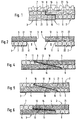
- the connecting seam 1 shown in Fig. 1 connects sections 2 and 3 an abrasive belt underlay.
- This consists of two layers, of layer 4 shown in section 2 above and section 4 3 layer 5 shown below, the longitudinal strength layer, for example threads 22 one running parallel to one another Layer of a thread layer sewing agent, contains, of which adopted be that they run parallel to the plane of the drawing.
- the two other layers 6 and 7 can accordingly extend in the transverse direction Threads 22 comprise and are therefore used as a transverse strength layer designated.
- the connecting seam shown in Fig. 1 comes about in that 2 to each other (shown without a grain layer) connecting edges in the area of their transverse strength layers 6 and 7 are milled to form a recess 8.
- the ones to be connected Edges are thus delimited by an end face 9, a approximately in the direction of the grinding belt, at the boundary 21 of the longitudinal strength layer extending surface 10 of the recess 8, which as Connection surface is referred to, and an end face 11 of the recess 8. Both depressions have the same dimensions.
- the longitudinal strength layers 4 and 5 can be of the same type Layers of the same document material can be formed, for example in the production of broad bands from the weft layer a pad that contains a thread ply sewing agent. 1 is then used to produce the connecting seam Section 3 turned 180 ° over the other section 2 and the edges to be joined are pushed into each other in such a way that their protruding edge strips of the longitudinal strength layer in each case come to rest in the recess 8 of the other section. In this layer they are between by an adhesive layer 13 the connecting surfaces 10 and the end faces 9, 11 with one another connected. It can be seen that the longitudinal forces without mediation special connecting element of a longitudinal strength layer 4 can pass into the other longitudinal strength layer 5. One notices also that the flexibility in the seam area is not due to use a connecting element that differs from the rest of the abrasive belt material is disturbed.
- the grain layer 14 is in the segment 2 from the longitudinal strength layer 4 and section 3 carried by the transverse strength layer 7. This assumes that both surfaces of the base material meet the minimum requirements for granulability. If the pad is grained before the sanding belt is assembled and assembled the basic material must be in two different ways There are types that differ on the grain Wear sides. This need does not apply if the document is submitted the grain is put together.
- the longitudinal strength layer of section 2 from the warp thread layer of the base material be formed, while the longitudinal strength layer 5 of section 3 from the weft layer of the Base material is formed.
- the two sections 2 and 3 are then in the assembled state in the same plane by 90 ° to each other twisted.
- This version assumes that both layers of the base material in the direction of its strength mediating strands with respect to the same mechanical properties Have strength and elongation. Is not required that their surfaces must be grainy in the same way because the grain layer in both sections on the same side of the Base material is attached.
- the finished sanding belt consists of at least two, at least an even number of sections with a corresponding number of connecting seams.
- the seam according to the invention can easily be machined and therefore Manufacture consistently reliably because there is no connecting element must be inserted. Rather, the edges to be joined, after they have been glued, easily automatically are pushed together until their end faces 9, 11 collide and then, if necessary, pressed and for curing the adhesive be treated. This pushing together of the edges to be joined succeeds more easily in the embodiments described below with sloping connection surface, if also they are provided with stop faces 9, 11.
- the surfaces the joined edges around the thickness of the adhesive layer 13 are slightly offset from each other in stages. This can be avoided 3, if the longitudinal strength layer by the thickness the adhesive layer is reduced or the connecting surfaces 10 according to the following embodiments.
- the longitudinal strength layers are 4, 5 and the transverse strength layers 6, 7 of the same thickness.
- the depression has an inclined connecting surface 10.
- deepening is not only in the transverse strength layer 6 or 7, but extends beyond this into the Longitudinal strength layer.
- This version has the advantage that the in the longitudinal strength layers 4 and 5 contained threads over a much of their cross-sectional dimension from the adhesive layer 13 are detected, so that a very uniform Power transmission can take place. This will prevent this Power transmission to a considerable extent in the longitudinal direction less resistant parts of the transverse strength layers 6 and 7 takes place.
- This embodiment avoids in comparison to the construction according to Fig.
- the connecting surfaces 10 exceed on both sides of the Adhesive layer 13 the boundaries 21 of the longitudinal strength layers and cut these layers in the area of large, opposing ones Stretch straight on so that an immediate and large-area connection of the longitudinal strength layers can.
- the inner edges 15 of the depressions lie here within the transverse strength layers 6 and 7 to some extent Thickness distance from the layer boundary of the longitudinal strength layers 4, 5.
- the longitudinal strength layers are therefore in terms of their Strength not affected by notch effects from the edges 15 going out. It is useful if the direct connection mentioned of the longitudinal strength layers in a range of one certain minimum length is present, which is at least about the thickness the longitudinal strength layer, better than five times this Thickness.
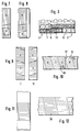
- FIG. 7 and 8 illustrate the composition of an abrasive belt (Fig. 8) from the blanks of a basic material web (Fig. 7), the two layers of which are approximately the same mechanical in each direction Have properties.
- a pad is suitable for this Includes thread layer sewing agent, which in the warp and weft direction approximately has the same strength and elongation.
- thread layer sewing agent which in the warp and weft direction approximately has the same strength and elongation.
- both a staple fiber yarn for both warp and weft The Nm 12 size can be used while the sewing thread is made of polyester filaments dtex 76 exists.
- the warp threads are tied in high-low weave, with at least two warp threads within one Nadelgasse.
- the warp direction is by longitudinal hatching specified. Between the ends of the section of any length A a section B is used to connect them, its cutting from the same basic goods in that indicated in Fig. 7 Order is made. This is compared to section A. Inserted rotated 90 ° in the same plane so that the warp direction - As indicated in Fig. 8 by hatching - runs transversely and the longitudinal strength layer is formed by the weft layer becomes.
- the basic goods can be assembled before the Abrasive tape should be grained, with the grain layer in the sections A and B on the same side of the pad, but once on the Cross-strength layer and once on the longitudinal strength layer of the sanding belt.
- FIG. 9 and 10 show the assembly of a Broadband from two lanes I and II of the basic goods, their documents match, but are grained on different sides.
- the sanding belt can also be made from one and the same Web of undigested basic goods manufactured and then grained become.
- the grinding belt Fig. 10
- sections are alternated the lanes I and II used, the sections from the lane II are facing those from lane I.
- Fig. 10 illustrated by the fact that in Fig. 9 by cross hatching indicated weft direction in the originating from lane I Sections A and B of the abrasive belt with full lines and in the sections C and D originating from web II with dashed lines Lines is indicated.
- the net thread direction runs in all sections parallel to the direction of the seams 16, which under the Seam angle alpha with respect to the band edge 17 are inclined. Perpendicular the weft direction 18 extends to the seam direction, which accordingly at the seam angle alpha with respect to the perpendicular 17 to the tape running direction is inclined. Since the favorable properties of the invention Sanding belt connection a large seam angle Alpha allow this deviation of the weft direction from the Tape running direction low and therefore the resin equipment of the Sanding belts should be lighter than usual.
Landscapes
- Engineering & Computer Science (AREA)
- Mechanical Engineering (AREA)
- Polishing Bodies And Polishing Tools (AREA)
Description
- Fig. 1
- den Nahtquerschnitt einer ersten Ausführungsform,
- Fig. 2
- eine Herstellungsvorstufe dieser Ausführungsform,
- Fig. 3
- eine Ausführungsform mit dünner Längsfestigkeits-schicht
- Fig. 4 bis 6
- weitere Ausführungsformen,
- Fig. 7 und 8
- die schematische Zuschnittdarstellung eines Schleifbands und
- Fig. 9 bis 12
- Zuschnittdarstellungen von zwei Ausführungsformen eines Schleifbreitbandes.
Claims (21)
- Schleifband mit einer Schleifkornschicht auf einer Seite einer flexiblen Unterlage, das folgende Merkmale aufweist:1. Die Unterlage umfaßt zwei Schichten, nämlich eine Längsfestigkeitsschicht (4, 5) die zur Aufnahme des größten Teils der in Bandlaufrichtung wirkenden Kräfte ausgebildet ist, und eine Querfestigkeitsschicht (6, 7), die zur Aufnahme des größeren Teils der quer zur Bandlaufrichtung verlaufenden Kräfte ausgebildet ist;2. das Schleifband ist aus mindestens zwei Abschnitten (2, 3) zusammengesetzt, deren Ränder durch mindestens eine quer zur Bandlaufrichtung verlaufende Klebenaht (1) miteinander verbunden sind;3. die durch die Klebenaht verbundenen Ränder enthalten auf der Seite der Querfestigkeitsschicht (6, 7) eine Vertiefung (8), die eine im Nahtquerschnitt etwa in Längsrichtung verlaufende Verbindungsfläche (10) bildet, die zumindest nahe an die Längsfestigkeitsschicht (4, 5) heranreicht;4. einer der beiden Abschnitte (2) trägt die Kornschicht (14) auf seiner Längsfestigkeitsschicht (4), der andere (3) auf seiner Querfestigkeitsschicht (7);5. die im Bereich der Vertiefung (8) vorstehenden Randstreifen (12) der Längsfestigkeitsschicht (4, 5) jedes der beiden Ränder liegt in der Vertiefung (8) des jeweils anderen Randes;6. die Verbindungsflächen (10) der beiden Vertiefungen sind unmittelbar miteinander verklebt.
- Schleifband nach Anspruch 1, dadurch gekennzeichnet, daß die Längsfestigkeitsschichten (4, 5) unmittelbar miteinander verklebt sind.
- Schleifband nach Anspruch 1 oder 2, dadurch gekennzeichnet, daß die Verbindungsflächen (10) oberflächenparallel etwa an der der Querfestigkeitsschicht zugewendeten Grenze (21) der Längsfestigkeitsschicht (4, 5) liegen.
- Schleifband nach Anspruch 1 oder 2, dadurch gekennzeichnet, daß die Verbindungsflächen (10) unter einem spitzen Winkel zur Grenze (21) der Längsfestigkeitsschicht (4, 5) verlaufen.
- Schleifband nach Anspruch 4, dadurch gekennzeichnet, daß die Verbindungsflächen (10) die Grenze (21) der Längsfestigkeitsschicht schneiden.
- Schleifband nach Anspruch 5, dadurch gekennzeichnet, daß das innere Ende (15) der Verbindungsflächen (10) in Abstand von der Längsfestigkeitsschicht (4, 5) in der Querfestigkeitsschicht (6, 7) liegt.
- Schleifband nach einem der Ansprüche 4 bis 6, dadurch gekennzeichnet, daß die in den Verbindungsflächen (10) frei liegenden Bereiche der Längsfestigkeitsschicht (4, 5) einander in einem Nahtabschnitt (14) unmittelbar gegenüberliegen, dessen Länge mindestens etwa der Dicke der Längsfestigkeitsschicht (4, 5) gleicht.
- Schleifband nach einem der Ansprüche 1 bis 7, dadurch gekennzeichnet, daß die Ränder oberflächengleich aneinander anschließen.
- Schleifband nach einem der Ansprüche 1 bis 8, dadurch gekennzeichnet, daß die Schichten (4, 5; 6, 7) gleich dick sind.
- Schleifband nach einem der Ansprüche 1 bis 8, dadurch gekennzeichnet, daß die Längsfestigkeitsschicht (4, 5) dicker als die Querfestigkeitsschicht (6, 7) ist.
- Schleifband nach einem der Ansprüche 1 bis 10, dadurch gekennzeichnet, daß die Längsfestigkeitsschicht (4, 5) dünner als die Querfestigkeitsschicht ist.
- Schleifband nach einem der Ansprüche 1 bis 11, dadurch gekennzeichnet, daß die beiden Oberflächen etwa gleiche Kornträgerqualität haben.
- Schleifband nach einem der Ansprüche 1 bis 12, dadurch gekennzeichnet, daß die Längsfestigkeitsschicht (4, 5) gestreckt und parallel zueinander verlaufende Fäden (22) enthält.
- Schleifband nach Anspruch 13, dadurch gekennzeichnet, daß die Fäden (22) Stapelfasern enthalten.
- Schleifband nach einem der Ansprüche 13 bis 14, dadurch gekennzeichnet, daß die Querfestigkeitsschicht (6, 7) Fäden (22) enthält, die in Querrichtung verlaufen.
- Schleifband nach Anspruch 13 oder 14, dadurch gekennzeichnet, daß die Unterlage eine Textilstruktur von der Art eines Fadenlagen-Nähwirkstoff enthält.
- Schleifband nach einem der Ansprüche 13 bis 16, dadurch gekennzeichnet, daß in beiden Abschnitten (2, 3) die Längsfestigkeitsschichten (4, 5) gleiche Herstellrichtung haben und im einen Abschnitt (2) die Herstelloberseite und im anderen Abschnitt die Herstellunterseite die Kornschicht (14) trägt.
- Schleifband nach Anspruch 15 oder 16, dadurch gekennzeichnet, daß beide Schichten (4, 5; 6, 7) in ihrer Fadenlaufrichtung etwa gleiche Festigkeits- und Dehnungseigenschaften aufweisen und die Längsfestigkeitsschicht (4) im einen Abschnitt (2) von der Schicht gebildet ist, in der die Fäden in Herstellrichtung verlaufen, während sie im anderen Abschnitt (3) von der Schicht (5) gebildet ist, in der die Fäden quer zur Herstellrichtung verlaufen.
- Schleifband nach einem der Ansprüche 1 bis 18, dadurch gekennzeichnet, daß die Ränder und Vertiefungen (8) quer zur Bandebene verlaufende Anschlagflächen (9, 11) bilden.
- Schleifband nach einem der Ansprüche 1 bis 19, dadurch gekennzeichnet, daß der Nahtwinkel Alpha zwischen der Klebenaht (16) und der Bandlaufrichtung (17) über 80° liegt.
- Schleifband nach den Ansprüche 17 und 20, dadurch gekennzeichnet, daß die Fäden der Längsfestigkeitsschicht in Bahnlaufrichtung verlaufen und der Nahtwinkel Alpha zwischen 60° und 90° liegt (Fig. 12).
Applications Claiming Priority (2)
| Application Number | Priority Date | Filing Date | Title |
|---|---|---|---|
| DE29518953U | 1995-11-29 | ||
| DE29518953U DE29518953U1 (de) | 1995-11-29 | 1995-11-29 | Schleifband |
Publications (2)
| Publication Number | Publication Date |
|---|---|
| EP0776734A1 EP0776734A1 (de) | 1997-06-04 |
| EP0776734B1 true EP0776734B1 (de) | 1999-10-27 |
Family
ID=8016084
Family Applications (1)
| Application Number | Title | Priority Date | Filing Date |
|---|---|---|---|
| EP96118125A Expired - Lifetime EP0776734B1 (de) | 1995-11-29 | 1996-11-12 | Schleifband |
Country Status (4)
| Country | Link |
|---|---|
| US (1) | US5700188A (de) |
| EP (1) | EP0776734B1 (de) |
| AT (1) | ATE186002T1 (de) |
| DE (2) | DE29518953U1 (de) |
Cited By (1)
| Publication number | Priority date | Publication date | Assignee | Title |
|---|---|---|---|---|
| WO2020142277A1 (en) * | 2018-12-31 | 2020-07-09 | Saint-Gobain Abrasives, Inc. | Coated abrasive film belt |
Families Citing this family (13)
| Publication number | Priority date | Publication date | Assignee | Title |
|---|---|---|---|---|
| US5681612A (en) * | 1993-06-17 | 1997-10-28 | Minnesota Mining And Manufacturing Company | Coated abrasives and methods of preparation |
| US6780096B1 (en) * | 2000-06-21 | 2004-08-24 | 3M Innovative Properties Company | Spiral wound abrasive belt and method |
| US20030194960A1 (en) * | 2002-04-10 | 2003-10-16 | Eric Staudt | Multiple polymer belt used as a carrier in a linear belt polishing system |
| US6805722B2 (en) | 2002-10-01 | 2004-10-19 | 3M Innovative Properties Company | Apparatus and method for forming a spiral wound abrasive article, and the resulting article |
| PL2895298T3 (pl) | 2012-09-05 | 2022-03-07 | Mirka Oy | Elastyczny produkt szlifujący z płaską powierzchnią i sposób jego wytwarzania |
| DE102013003641A1 (de) | 2013-03-05 | 2014-09-11 | Lohmann Gmbh & Co. Kg | Winkelgewebe, dessen Herstellung und Verwendung |
| USD807045S1 (en) | 2015-05-08 | 2018-01-09 | Mirka Oy | Abrasive material |
| KR20170140311A (ko) | 2015-05-08 | 2017-12-20 | 미르카 리미티드 | 연마 벨트 연삭 제품 |
| DE202015009577U1 (de) | 2015-05-08 | 2018-06-28 | Mirka Ltd. | Schleifband-Schleifprodukt |
| DE202015103867U1 (de) | 2015-05-08 | 2016-08-10 | Kwh Mirka Ltd. | Schleifband/Schleifprodukt |
| USD821698S1 (en) * | 2017-03-03 | 2018-07-03 | Hermes Sellier (Société par Actions Simplifiée) | Belt |
| CN111015537A (zh) * | 2019-12-20 | 2020-04-17 | 贲庆飞 | 一种砂布转接砂带双面无痕接口生产工艺 |
| CN114774009A (zh) * | 2022-05-07 | 2022-07-22 | 程伯强 | 一种砂带对接胶带及其制备方法 |
Family Cites Families (15)
| Publication number | Priority date | Publication date | Assignee | Title |
|---|---|---|---|---|
| US1728673A (en) | 1929-09-17 | Joint eor abrasive belts | ||
| US2350861A (en) * | 1942-09-24 | 1944-06-06 | Carborundum Co | Abrasive belt joint |
| US3637359A (en) * | 1970-01-06 | 1972-01-25 | Norton Co | Coated abrasive belt overlap joint |
| SE338933B (de) | 1970-01-20 | 1971-09-20 | Fab Ab Eka | |
| US4018574A (en) * | 1970-12-16 | 1977-04-19 | Norton Compay | Process for the manufacture of endless coated abrasive articles |
| US4215516A (en) | 1979-04-18 | 1980-08-05 | Sheldahl, Inc. | Unidirectional tape |
| JPS6048264A (ja) * | 1983-08-26 | 1985-03-15 | Ryozo Abo | 接合研摩布紙ベルト |
| US4589233A (en) * | 1984-06-25 | 1986-05-20 | Carborundum Abrasives Company | Sectional abrasive belt |
| DE3526502A1 (de) * | 1985-07-24 | 1987-01-29 | Norddeutsche Schleifmittel Ind | Schleifband mit einer quer zu seiner laengsrichtung verlaufenden verbindungsfuge |
| WO1990008035A1 (en) * | 1989-01-23 | 1990-07-26 | Plastiroll Oy | Method for manufacturing of laminate material |
| US5341609A (en) * | 1992-01-28 | 1994-08-30 | Minnesota Mining And Manufacturing Company | Abrasive belts and their manufacture |
| US5256227A (en) * | 1991-05-09 | 1993-10-26 | Minnesota Mining And Manufacturing Company | Method of splicing endless abrasive belts and cones |
| DE69228487T2 (de) * | 1991-12-20 | 1999-09-02 | Minnesota Mining And Mfg. Co. | Ueberzogenes schleifband mit endlosem, verbandfreiem traeger und herstellungsverfahren |
| GB9310398D0 (en) * | 1993-05-20 | 1993-07-07 | Minnisota Mining And Manufactu | Process for the manufacture of endless coated abrasive articles |
| US5595804A (en) * | 1994-08-22 | 1997-01-21 | Minnesota Mining And Manufacturing Company | Splice means, a method of splicing an abrasive article with same and the spliced abrasive article formed thereby |
-
1995
- 1995-11-29 DE DE29518953U patent/DE29518953U1/de not_active Expired - Lifetime
-
1996
- 1996-11-12 DE DE59603478T patent/DE59603478D1/de not_active Expired - Lifetime
- 1996-11-12 EP EP96118125A patent/EP0776734B1/de not_active Expired - Lifetime
- 1996-11-12 AT AT96118125T patent/ATE186002T1/de active
- 1996-11-26 US US08/756,481 patent/US5700188A/en not_active Expired - Lifetime
Cited By (3)
| Publication number | Priority date | Publication date | Assignee | Title |
|---|---|---|---|---|
| WO2020142277A1 (en) * | 2018-12-31 | 2020-07-09 | Saint-Gobain Abrasives, Inc. | Coated abrasive film belt |
| US11529764B2 (en) | 2018-12-31 | 2022-12-20 | Saint-Gobain Abrasives, Inc. | Coated abrasive film belt |
| US12311614B2 (en) | 2018-12-31 | 2025-05-27 | Saint-Gobain Abrasives, Inc. | Coated abrasive film belt |
Also Published As
| Publication number | Publication date |
|---|---|
| EP0776734A1 (de) | 1997-06-04 |
| ATE186002T1 (de) | 1999-11-15 |
| DE59603478D1 (de) | 1999-12-02 |
| US5700188A (en) | 1997-12-23 |
| DE29518953U1 (de) | 1997-03-27 |
Similar Documents
| Publication | Publication Date | Title |
|---|---|---|
| EP0510715B1 (de) | Verfahren zum Anbringen von elastischen Elementen um Beinöffnungen von Wegwerfbekleidungsstücken | |
| DE3445367C1 (de) | Verbundgewebe als Papiermaschinensieb | |
| DE2452589A1 (de) | Endloses, flexibles schleifband und verfahren zu seiner herstellung | |
| EP0261488B1 (de) | Maschinenfilz sowie Verfahren zur Herstellung desselben | |
| DD285386A5 (de) | Bauteil auf velours-gewebebasis und verfahren zu seiner herstellung | |
| DE2164700A1 (de) | Tuch zur Herstellung von Papier und Zellulose | |
| EP0776734A1 (de) | Schleifband | |
| DE2825191A1 (de) | Verfahren zur herstellung eines durch kohlefaeden verstaerkten zahnradmaterials sowie das dabei erhaltene material | |
| EP1837440B1 (de) | Verfahren zur Herstellung eines Filzbandes sowie Filzband | |
| EP1002892A1 (de) | Textiles Flächengebilde | |
| EP0213353B1 (de) | Schleifband mit einer quer zu seiner Längsrichtung verlaufenden Verbindungsfuge | |
| DE2355338A1 (de) | Verstaerkungseinlage in form eines guertels fuer fahrzeugluftreifen | |
| DE102004010768B4 (de) | Blattfeder für eine Radaufhängung an einem Fahrzeug | |
| DE69223596T2 (de) | Verbundstoff mit diagonaler Holzmaserung | |
| WO1992012281A1 (de) | Abdeckvlies | |
| DE1912317C3 (de) | Endschlaufe eines streifenförmigen Gewebematerials hoher Festigkeit | |
| DE69917048T2 (de) | Verbundwerkstoffkonstruktion | |
| EP0063260B1 (de) | Betonrohr mit einer inneren Auskleidung | |
| DE29904546U1 (de) | Papiermaschinenfilz | |
| DE3700499C2 (de) | Bohrender und selbstschneidender Befestiger | |
| DE2229888A1 (de) | Stahlguertel fuer fahrzeugluftreifen | |
| DE2064085A1 (en) | Splicing of fabric ends - particularly multilayer papermaking dryer fabrics | |
| DE69705682T2 (de) | Verbundwerkstoffkonstruktion | |
| DE102020128398A1 (de) | Verbundbauteilsystem, Verwendung eines Verbundbauteilsystems sowie Verfahren zum Reparieren eines Verbundbauteilsystems | |
| DE1960717A1 (de) | Windelgewebe und daraus hergestellte Windeln |
Legal Events
| Date | Code | Title | Description |
|---|---|---|---|
| PUAI | Public reference made under article 153(3) epc to a published international application that has entered the european phase |
Free format text: ORIGINAL CODE: 0009012 |
|
| AK | Designated contracting states |
Kind code of ref document: A1 Designated state(s): AT CH DE FR GB IT LI SE |
|
| 17P | Request for examination filed |
Effective date: 19970415 |
|
| GRAG | Despatch of communication of intention to grant |
Free format text: ORIGINAL CODE: EPIDOS AGRA |
|
| GRAG | Despatch of communication of intention to grant |
Free format text: ORIGINAL CODE: EPIDOS AGRA |
|
| GRAH | Despatch of communication of intention to grant a patent |
Free format text: ORIGINAL CODE: EPIDOS IGRA |
|
| 17Q | First examination report despatched |
Effective date: 19990407 |
|
| GRAH | Despatch of communication of intention to grant a patent |
Free format text: ORIGINAL CODE: EPIDOS IGRA |
|
| GRAA | (expected) grant |
Free format text: ORIGINAL CODE: 0009210 |
|
| AK | Designated contracting states |
Kind code of ref document: B1 Designated state(s): AT CH DE FR GB IT LI SE |
|
| REF | Corresponds to: |
Ref document number: 186002 Country of ref document: AT Date of ref document: 19991115 Kind code of ref document: T |
|
| REG | Reference to a national code |
Ref country code: CH Ref legal event code: EP |
|
| REG | Reference to a national code |
Ref country code: CH Ref legal event code: NV Representative=s name: TROESCH SCHEIDEGGER WERNER AG |
|
| REF | Corresponds to: |
Ref document number: 59603478 Country of ref document: DE Date of ref document: 19991202 |
|
| ET | Fr: translation filed | ||
| ITF | It: translation for a ep patent filed | ||
| GBT | Gb: translation of ep patent filed (gb section 77(6)(a)/1977) |
Effective date: 20000127 |
|
| PLBE | No opposition filed within time limit |
Free format text: ORIGINAL CODE: 0009261 |
|
| STAA | Information on the status of an ep patent application or granted ep patent |
Free format text: STATUS: NO OPPOSITION FILED WITHIN TIME LIMIT |
|
| 26N | No opposition filed | ||
| REG | Reference to a national code |
Ref country code: GB Ref legal event code: IF02 |
|
| PGFP | Annual fee paid to national office [announced via postgrant information from national office to epo] |
Ref country code: AT Payment date: 20101119 Year of fee payment: 15 |
|
| PGFP | Annual fee paid to national office [announced via postgrant information from national office to epo] |
Ref country code: IT Payment date: 20101126 Year of fee payment: 15 Ref country code: GB Payment date: 20101123 Year of fee payment: 15 |
|
| PGFP | Annual fee paid to national office [announced via postgrant information from national office to epo] |
Ref country code: SE Payment date: 20111122 Year of fee payment: 16 Ref country code: CH Payment date: 20111124 Year of fee payment: 16 Ref country code: FR Payment date: 20111125 Year of fee payment: 16 |
|
| REG | Reference to a national code |
Ref country code: CH Ref legal event code: PL |
|
| REG | Reference to a national code |
Ref country code: AT Ref legal event code: MM01 Ref document number: 186002 Country of ref document: AT Kind code of ref document: T Effective date: 20121112 |
|
| GBPC | Gb: european patent ceased through non-payment of renewal fee |
Effective date: 20121112 |
|
| PG25 | Lapsed in a contracting state [announced via postgrant information from national office to epo] |
Ref country code: SE Free format text: LAPSE BECAUSE OF NON-PAYMENT OF DUE FEES Effective date: 20121113 Ref country code: LI Free format text: LAPSE BECAUSE OF NON-PAYMENT OF DUE FEES Effective date: 20121130 Ref country code: AT Free format text: LAPSE BECAUSE OF NON-PAYMENT OF DUE FEES Effective date: 20121112 Ref country code: CH Free format text: LAPSE BECAUSE OF NON-PAYMENT OF DUE FEES Effective date: 20121130 |
|
| REG | Reference to a national code |
Ref country code: FR Ref legal event code: ST Effective date: 20130731 |
|
| PG25 | Lapsed in a contracting state [announced via postgrant information from national office to epo] |
Ref country code: IT Free format text: LAPSE BECAUSE OF NON-PAYMENT OF DUE FEES Effective date: 20121112 |
|
| PG25 | Lapsed in a contracting state [announced via postgrant information from national office to epo] |
Ref country code: GB Free format text: LAPSE BECAUSE OF NON-PAYMENT OF DUE FEES Effective date: 20121112 Ref country code: FR Free format text: LAPSE BECAUSE OF NON-PAYMENT OF DUE FEES Effective date: 20121130 |
|
| PGFP | Annual fee paid to national office [announced via postgrant information from national office to epo] |
Ref country code: DE Payment date: 20140122 Year of fee payment: 18 |
|
| REG | Reference to a national code |
Ref country code: DE Ref legal event code: R119 Ref document number: 59603478 Country of ref document: DE |
|
| PG25 | Lapsed in a contracting state [announced via postgrant information from national office to epo] |
Ref country code: DE Free format text: LAPSE BECAUSE OF NON-PAYMENT OF DUE FEES Effective date: 20150602 |