EP0774577B1 - Flüssigkeitsgekühlter Zylinderkopf für eine mehrzylindrige Brennkraftmaschine - Google Patents
Flüssigkeitsgekühlter Zylinderkopf für eine mehrzylindrige Brennkraftmaschine Download PDFInfo
- Publication number
- EP0774577B1 EP0774577B1 EP96115354A EP96115354A EP0774577B1 EP 0774577 B1 EP0774577 B1 EP 0774577B1 EP 96115354 A EP96115354 A EP 96115354A EP 96115354 A EP96115354 A EP 96115354A EP 0774577 B1 EP0774577 B1 EP 0774577B1
- Authority
- EP
- European Patent Office
- Prior art keywords
- cylinder head
- rib
- coolant
- coolant chamber
- chamber
- Prior art date
- Legal status (The legal status is an assumption and is not a legal conclusion. Google has not performed a legal analysis and makes no representation as to the accuracy of the status listed.)
- Expired - Lifetime
Links
- 238000002485 combustion reaction Methods 0.000 title claims description 22
- 239000007788 liquid Substances 0.000 title 1
- 239000002826 coolant Substances 0.000 claims 14
- 239000000498 cooling water Substances 0.000 description 37
- 238000001816 cooling Methods 0.000 description 11
- 230000000694 effects Effects 0.000 description 3
- 238000005266 casting Methods 0.000 description 2
- 239000008141 laxative Substances 0.000 description 2
- 230000002475 laxative effect Effects 0.000 description 2
- 238000004519 manufacturing process Methods 0.000 description 2
- 230000015572 biosynthetic process Effects 0.000 description 1
- 230000007423 decrease Effects 0.000 description 1
- 238000002347 injection Methods 0.000 description 1
- 239000007924 injection Substances 0.000 description 1
Images

Classifications
-
- F—MECHANICAL ENGINEERING; LIGHTING; HEATING; WEAPONS; BLASTING
- F02—COMBUSTION ENGINES; HOT-GAS OR COMBUSTION-PRODUCT ENGINE PLANTS
- F02F—CYLINDERS, PISTONS OR CASINGS, FOR COMBUSTION ENGINES; ARRANGEMENTS OF SEALINGS IN COMBUSTION ENGINES
- F02F1/00—Cylinders; Cylinder heads
- F02F1/24—Cylinder heads
- F02F1/26—Cylinder heads having cooling means
- F02F1/36—Cylinder heads having cooling means for liquid cooling
- F02F1/40—Cylinder heads having cooling means for liquid cooling cylinder heads with means for directing, guiding, or distributing liquid stream
-
- F—MECHANICAL ENGINEERING; LIGHTING; HEATING; WEAPONS; BLASTING
- F02—COMBUSTION ENGINES; HOT-GAS OR COMBUSTION-PRODUCT ENGINE PLANTS
- F02B—INTERNAL-COMBUSTION PISTON ENGINES; COMBUSTION ENGINES IN GENERAL
- F02B1/00—Engines characterised by fuel-air mixture compression
- F02B1/02—Engines characterised by fuel-air mixture compression with positive ignition
- F02B1/04—Engines characterised by fuel-air mixture compression with positive ignition with fuel-air mixture admission into cylinder
-
- F—MECHANICAL ENGINEERING; LIGHTING; HEATING; WEAPONS; BLASTING
- F02—COMBUSTION ENGINES; HOT-GAS OR COMBUSTION-PRODUCT ENGINE PLANTS
- F02B—INTERNAL-COMBUSTION PISTON ENGINES; COMBUSTION ENGINES IN GENERAL
- F02B75/00—Other engines
- F02B75/16—Engines characterised by number of cylinders, e.g. single-cylinder engines
- F02B75/18—Multi-cylinder engines
- F02B2075/1804—Number of cylinders
- F02B2075/1812—Number of cylinders three
-
- F—MECHANICAL ENGINEERING; LIGHTING; HEATING; WEAPONS; BLASTING
- F02—COMBUSTION ENGINES; HOT-GAS OR COMBUSTION-PRODUCT ENGINE PLANTS
- F02F—CYLINDERS, PISTONS OR CASINGS, FOR COMBUSTION ENGINES; ARRANGEMENTS OF SEALINGS IN COMBUSTION ENGINES
- F02F1/00—Cylinders; Cylinder heads
- F02F1/24—Cylinder heads
- F02F2001/244—Arrangement of valve stems in cylinder heads
- F02F2001/245—Arrangement of valve stems in cylinder heads the valve stems being orientated at an angle with the cylinder axis
Definitions
- the invention relates to a liquid-cooled cylinder head for a multi-cylinder internal combustion engine according to that Preamble of main claim 1.
- a generic cylinder head is one Internal combustion engine known that one between outer walls, a cylinder head base and a cylinder head cover, Has cooling water space, which in the direction of a longitudinal axis the cooling water flows through the cylinder head. Which does ________ mean, that the cooling effect decreases continuously in the longitudinal direction of the cylinder head. This temperature gradient in the cylinder head longitudinal direction leads to an increasing load on the cylinder head in this Direction.
- a rib is formed on the cylinder head cover, the protrudes into the cooling water chamber in the direction of the cylinder head base and in the cylinder head cross-axis direction between two combustion chambers is arranged. Through the rib, this is in the cylinder head longitudinal axis direction flowing cooling water towards the cylinder head floor in a rather less temperature-stressed Redirected area between two combustion chambers.
- An advantage of the liquid-cooled cylinder head according to the invention lies in the improved cooling of the cylinder head base in the individual cooling water chamber sections each assigned to a combustion chamber.
- the molded on the cylinder head cover Ribs form guiding elements through which the flow of cooling water is deflected in the direction of the cylinder head base.
- the Cooling water bounces between the inlet and outlet channels in the area the highest combustion chamber temperatures on the cylinder head floor on.
- the contact of the cooling water flow to the cylinder head floor is improved and thereby increases the heat transfer from temperature-stressed Cylinder head floor for cooling water.
- the rib reduces the flow cross-section, what with an increase in flow velocity is connected at this point and consequently the cooling effect the endangered areas on the cylinder head floor again increased.
- the embodiment of the invention according to claim 2 enables one targeted cooling of the between the valve channels central area of the combustion chamber that is subject to extremely high temperatures Cylinder head bottom section.
- the embodiment of the invention according to claims 2 and 5 enables a simple manufacture of the cylinder head.
- Through the symmetrical formation and the trapezoidal shape of the rib can be a simple manufacture of a casting core to produce the one-piece cylinder head designed as a housing are made possible. This is advantageously supported in that the Ribs evenly spaced towards one another Longitudinal center plane of the combustion chamber are arranged distributed. Further allows the trapezoidal shape of the rib to optimize the Flow resistance.
- the ribs according to claims 3 and 4 advantageously form Guide elements that influence the flow direction of the cooling water, by the cooling water flow flowing through the cooling water space strikes the lateral surface of the rib in the transverse direction and is directed in the direction of the cylinder head base.
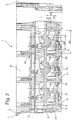
- a cylinder head 1 for a multi-cylinder, not shown here Internal combustion engine consists of a one-piece casting with a cylinder head base 2 and up from this up to a cover parting level 3, for supporting a cylinder head cover, laxative longitudinal outer walls 4,5 and front External walls 6.7.
- Control room 10 is divided.
- the cylinder head base 2 has a for each cylinder Recess designed combustion chamber 11, which has two orifices 12, 13 per cylinder and two more in the Combustion chamber 11 leading openings 14, 15 of chambers 16, 17 for Inclusion of spark plugs, injection nozzles or the like.
- From Valve channels 18, 19 extend from the orifices 12, 13, which the cooling water chamber 9 up to the longitudinal outer walls 4, 5 enforce.
- the from the mouth opening 12 to the outer wall 4 laxative valve channel 18 forms the inlet channel and valve channel leading from the mouth opening 13 to the outer wall 5 19 forms the outlet channel.
- the V-shaped to each other Chambers 16, 17 pass through the cooling water chamber 9 in the direction of Cylinder head cover 8.
- Inlet openings 20, 22 flow cooling water into the cooling water space 9 a.
- the cooling water flowing in through the inlet opening 20 flows through the cooling water chamber 9 approximately in the direction of a transverse axis 21 of the cylinder head 1.
- the cooling water then flows by a on the longitudinal outer wall 4 of the cylinder head 1 arranged, not shown outlet opening on the side of the inlet duct 18.
- a rib 23 is formed, which in the direction of the cylinder head base 2, freely hanging essentially transversely protrudes into the cooling water chamber 9 for the cooling water flow.
- the Cooling water hits the rib 23 and is targeted in the direction of the cylinder head base 2 in the highly temperature-stressed
- the area between inlet 18 and outlet channel 19 is deflected.
- the cooling water chamber 9 is divided into the same cooling water chamber sections 24, each assigned to one of the combustion chambers 11 are. Between the individual cooling water sections 24 of the cylinders extend from the cylinder head base 2 to Cylinder head cover 8 reaching Z-shaped retaining walls 25.
- the cylinder head cover 8 extends from the front outer walls 6, 7 over the entire width of the cylinder head 1.
- each cooling water space section 24 associated with the rib 23 which in Cooling water chamber 9 in the direction of a longitudinal median plane 26 of the Combustion chamber 11 is arranged.
- the rib 23 is approximately symmetrical centrally in the extension of the longitudinal center plane 26 of the combustion chamber 11 arranged on the cylinder head cover 8.
- the height 27 of the Rib 23 corresponds to at least half the height 28 of the cooling water space 9
- the length 29 of the rib 23 corresponds at least to that half length 30 of the extending in the direction of the longitudinal central axis 31
- Cooling water space section 24 and the width 32 of the Rib 23 corresponds to at least half the length 33 of the in Transverse direction 21 extending cooling water chamber section 24.
- Die Rib 23 has a trapezoidal shape, the short edge 34 hanging freely protrudes into the cooling water chamber 9, whereby a targeted Part of the cooling water flow in the direction of the cylinder head base 2 is reached. This is an improved Cooling of partial areas of the cylinder head base 2 without substantial increase in flow resistance possible.
Landscapes
- Engineering & Computer Science (AREA)
- Chemical & Material Sciences (AREA)
- Combustion & Propulsion (AREA)
- Mechanical Engineering (AREA)
- General Engineering & Computer Science (AREA)
- Cylinder Crankcases Of Internal Combustion Engines (AREA)
Description
- Fig. 1
- einen Querschnitt durch einen erfindungsgemäßen Zylinderkopf und
- Fig. 2
- den Zylinderkopf aus Fig. 1 im Längsschnitt.
Claims (5)
- Flüssigkeitsgekühlter Zylinderkopf für eine mehrzylindrige Brennkraftmaschine mit einem Kühlwasserraum, der von Außenwänden, einer mit Abstand über diesem angeordneten Zylinderkopfdekke und einem Zylinderkopfboden begrenzt wird, der für jeden Zylinder einen Brennraum aufweist, und mit mindestens einem sich zwischen Zylinderkopfdecke und Zylinderkopfboden im Kühlwasserraum erstreckenden Strömungsleitelement, das als Rippe ausgebildet ist, welche an der Zylinderkopfdecke angeformt ist und in Richtung des Zylinderkopfbodens, frei hängend im wesentlichen quer zur Kühlwasserströmung, in den Kühlwasserraum hineinragt,
dadurch gekennzeichnet,
daß der Kühlwasserraum (9) sich in Kühlwasserraumabschnitte (24) gliedert, die etwa in Richtung einer Querachse (21) des Zylinderkopfes (1) durchströmt werden, wobei jedem Kühlwasserraumabschnitt (24) eine Rippe (23) zugeordnet ist, welche im Kühlwasserraum (9) in Richtung einer Längsmittelebene (26) des Brennraumes (11) angeordnet ist und das Kühlwasser in Richtung des Zylinderkopfbodens (2) in einen Bereich zwischen Einlaßkanal (18) und Auslaßkanal (19) umlenkt. - Flüssigkeitsgekühlter Zylinderkopf nach Anspruch 1,
dadurch gekennzeichnet,
daß die Rippe (23) in etwa symmetrisch mittig in Verlängerung der Längsmittelebene (26) des Brennraumes (11) angeordnet ist. - Flüssigkeitsgekühlter Zylinderkopf nach Anspruch 1 oder 2,
dadurch gekennzeichnet,
daß die Höhe (27) der Rippe (23) mindestens der halben Höhe (28) des Kühlwasserraumes (9) entspricht. - Flüssigkeitsgekühlter Zylinderkopf nach einem der vorhergehenden Ansprüche,
dadurch gekennzeichnet,
daß die Länge (29) der Rippe (23) mindestens der halben Länge (30) des sich in Richtung der Längsmittelachse (31) erstreckenden Kühlwasserraumabschnittes (24) entspricht. - Flüssigkeitsgekühlter Zylinderkopf nach einem der vorhergehenden Ansprüche,
dadurch gekennzeichnet,
daß die Rippe (23) Trapezform besitzt, wobei die kurze Kante (34) freihängend in den Kühlwasserraum (9) hineinragt.
Applications Claiming Priority (2)
| Application Number | Priority Date | Filing Date | Title |
|---|---|---|---|
| DE19542494 | 1995-11-15 | ||
| DE19542494A DE19542494C1 (de) | 1995-11-15 | 1995-11-15 | Flüssigkeitsgekühlter Zylinderkopf für eine mehrzylindrige Brennkraftmaschine |
Publications (2)
| Publication Number | Publication Date |
|---|---|
| EP0774577A1 EP0774577A1 (de) | 1997-05-21 |
| EP0774577B1 true EP0774577B1 (de) | 1998-12-09 |
Family
ID=7777471
Family Applications (1)
| Application Number | Title | Priority Date | Filing Date |
|---|---|---|---|
| EP96115354A Expired - Lifetime EP0774577B1 (de) | 1995-11-15 | 1996-09-25 | Flüssigkeitsgekühlter Zylinderkopf für eine mehrzylindrige Brennkraftmaschine |
Country Status (4)
| Country | Link |
|---|---|
| US (1) | US5799627A (de) |
| EP (1) | EP0774577B1 (de) |
| DE (2) | DE19542494C1 (de) |
| ES (1) | ES2127598T3 (de) |
Cited By (1)
| Publication number | Priority date | Publication date | Assignee | Title |
|---|---|---|---|---|
| DE102004005749B4 (de) * | 2004-02-05 | 2014-01-02 | GM Global Technology Operations LLC (n. d. Ges. d. Staates Delaware) | Kühlflüssigkeitsummantelter Zylinderkopf mit optimiertem Kühlflüssigkeitsraum |
Families Citing this family (20)
| Publication number | Priority date | Publication date | Assignee | Title |
|---|---|---|---|---|
| PT816661E (pt) * | 1996-07-06 | 2003-03-31 | Volkswagen Ag | Cabeca de cilindros para uma maquina de combustao interna |
| JPH10288081A (ja) * | 1997-04-12 | 1998-10-27 | Yamaha Motor Co Ltd | 筒内燃料噴射式エンジンにおける燃料噴射弁周りの冷却構造 |
| FR2770585B1 (fr) * | 1997-11-06 | 2000-01-14 | Peugeot | Moteur a combustion interne a injection directe comportant des moyens de refroidissement des injecteurs |
| JP2000186615A (ja) * | 1998-12-18 | 2000-07-04 | Nissan Motor Co Ltd | 直噴火花点火式内燃機関 |
| DE19937122C1 (de) * | 1999-08-06 | 2000-10-26 | Daimler Chrysler Ag | Flüssigkeitsgekühlter Zylinderkopf |
| DE19943003C1 (de) * | 1999-09-09 | 2000-11-09 | Porsche Ag | Zylinderkopf für eine wassergekühlte Brennkraftmaschine |
| DE19943001C1 (de) | 1999-09-09 | 2000-10-26 | Porsche Ag | Zylinderkopf für eine wassergekühlte Brennkraftmaschine |
| US6363893B1 (en) | 2001-04-03 | 2002-04-02 | Honda Giken Kogyo Kabushiki Kaisha | Water jacket for multi-cylinder internal combustion engine |
| JP3700836B2 (ja) | 2001-05-17 | 2005-09-28 | 本田技研工業株式会社 | 内燃機関のシリンダヘッドの冷却構造 |
| DE10251360B4 (de) * | 2002-11-05 | 2005-01-20 | Daimlerchrysler Ag | Flüssigkeitsgekühlter Zylinderkopf |
| DE10306695A1 (de) * | 2003-02-18 | 2004-09-16 | Daimlerchrysler Ag | Brennkraftmaschine mit einem Kühlmittelkreislauf |
| DE10328460A1 (de) * | 2003-06-25 | 2005-01-13 | Daimlerchrysler Ag | Zylinderkopf einer flüssigkeitsgekühlten Brennkraftmaschine |
| JP2006052666A (ja) * | 2004-08-11 | 2006-02-23 | Nissan Motor Co Ltd | 筒内直接噴射式内燃機関 |
| US7240644B1 (en) * | 2006-06-07 | 2007-07-10 | Ford Global Technologies, Llc | Internal combustion engine with cylinder head having directed cooling |
| JP4756381B2 (ja) * | 2007-02-07 | 2011-08-24 | トヨタ自動車株式会社 | 多気筒エンジンの冷却装置 |
| KR101055832B1 (ko) * | 2008-11-20 | 2011-08-09 | 기아자동차주식회사 | 가솔린 직접 분사 엔진의 냉각장치 |
| US8539929B2 (en) | 2009-11-18 | 2013-09-24 | Harley-Davidson Motor Company | Cylinder head cooling system |
| DE102010052830A1 (de) | 2010-11-29 | 2012-05-31 | GM Global Technology Operations LLC | Zylinderkopf mit Flüssigkeitskühlung und Verfahren zur Kühlung des Zylinderkopfes |
| JP6759160B2 (ja) * | 2017-06-30 | 2020-09-23 | 株式会社クボタ | 水冷エンジン |
| US11300072B1 (en) * | 2021-05-12 | 2022-04-12 | Ford Global Technologies, Llc | Cylinder head for an internal combustion engine |
Family Cites Families (9)
| Publication number | Priority date | Publication date | Assignee | Title |
|---|---|---|---|---|
| US2205646A (en) * | 1938-01-20 | 1940-06-25 | Permold Co | Cylinder head |
| DE2452999C2 (de) * | 1974-11-08 | 1982-09-16 | Motoren-Werke Mannheim AG vorm. Benz Abt. stationärer Motorenbau, 6800 Mannheim | Zylinderkopf für eine wassergekühlte Dieselmaschine |
| JPS56148647A (en) * | 1980-04-22 | 1981-11-18 | Nissan Motor Co Ltd | Cooling water jacket of internal combustion engine cylinder head |
| JPS60113050A (ja) * | 1983-11-25 | 1985-06-19 | Mazda Motor Corp | エンジンのシリンダヘツド構造 |
| JPS61167145A (ja) * | 1985-01-19 | 1986-07-28 | Mazda Motor Corp | Dohc多気筒エンジンのシリンダヘツド構造 |
| JPS61268849A (ja) * | 1985-05-24 | 1986-11-28 | Toyota Motor Corp | 内燃機関のシリンダヘツドの冷却水通路構造 |
| JPH07103828B2 (ja) * | 1987-11-17 | 1995-11-08 | 本田技研工業株式会社 | 水冷式多気筒エンジンのシリンダヘッド |
| DE3819655C1 (de) * | 1988-06-09 | 1989-01-26 | Daimler-Benz Ag, 7000 Stuttgart, De | |
| DE4116943C2 (de) * | 1991-05-24 | 1997-05-22 | Daimler Benz Ag | Flüssigkeitsgekühlter Vierventil-Zylinderkopf für eine mehrzylindrige Brennkraftmaschine |
-
1995
- 1995-11-15 DE DE19542494A patent/DE19542494C1/de not_active Expired - Lifetime
-
1996
- 1996-09-25 DE DE59600960T patent/DE59600960D1/de not_active Expired - Fee Related
- 1996-09-25 EP EP96115354A patent/EP0774577B1/de not_active Expired - Lifetime
- 1996-09-25 ES ES96115354T patent/ES2127598T3/es not_active Expired - Lifetime
- 1996-11-05 US US08/744,011 patent/US5799627A/en not_active Expired - Fee Related
Cited By (1)
| Publication number | Priority date | Publication date | Assignee | Title |
|---|---|---|---|---|
| DE102004005749B4 (de) * | 2004-02-05 | 2014-01-02 | GM Global Technology Operations LLC (n. d. Ges. d. Staates Delaware) | Kühlflüssigkeitsummantelter Zylinderkopf mit optimiertem Kühlflüssigkeitsraum |
Also Published As
| Publication number | Publication date |
|---|---|
| DE59600960D1 (de) | 1999-01-21 |
| US5799627A (en) | 1998-09-01 |
| EP0774577A1 (de) | 1997-05-21 |
| DE19542494C1 (de) | 1997-01-30 |
| ES2127598T3 (es) | 1999-04-16 |
Similar Documents
| Publication | Publication Date | Title |
|---|---|---|
| DE19542494C1 (de) | Flüssigkeitsgekühlter Zylinderkopf für eine mehrzylindrige Brennkraftmaschine | |
| DE3516453C2 (de) | ||
| DE4441507C3 (de) | Gekühlte Turbinenschaufel | |
| EP0838585B1 (de) | Zylinderkopf einer Mehrzylinder-Brennkraftmaschine | |
| AT519458B1 (de) | Zylinderkopf für eine brennkraftmaschine | |
| EP0345431A2 (de) | Flüssigkeitsgekühlter Vierventil-Zylinderkopf für eine mehrzylindrige Brennkraftmaschine | |
| DE1476397A1 (de) | Wassergekuehlte Brennkraftmaschine | |
| AT402325B (de) | Zylinderkopf einer flüssigkeitsgekühlten brennkraftmaschine mit in reihe angeordneten zylindern | |
| DE4116943C2 (de) | Flüssigkeitsgekühlter Vierventil-Zylinderkopf für eine mehrzylindrige Brennkraftmaschine | |
| EP0774576B1 (de) | Flüssigkeitsgekühlter Zylinderkopf für eine mehrzylindrige Brennkraftmaschine | |
| EP0154144B1 (de) | Luftgekühlte Hubkolbenbrennkraftmaschine | |
| DE3224945C1 (de) | Zylinderkopf fuer fluessigkeitsgekuehlte Mehrzylinder-Brennkraftmaschinen | |
| DE10321035B3 (de) | Brennkraftmaschine mit einem Zylinderkopf | |
| DE10048582B4 (de) | Flüssigkeitsgekühlter Zylinderkopf für eine Brennkraftmaschine | |
| DE102014118060A1 (de) | Zylinderblock einer flüssigkeitsgekühlten Verbrennungskraftmaschine in Monoblock-Bauweise und Gießform zu dessen Herstellung | |
| DE69506477T2 (de) | Zylinderkopf für Dieselbrennkraftmaschine | |
| EP1083328A2 (de) | Zylinderkopf für eine wassergekühlte Brennkraftmaschine | |
| DE3435386A1 (de) | Luftgekuehlte mehrzylinder-brennkraftmaschine | |
| DE102007048021A1 (de) | Flüssigkeitsgekühlter Zylinderkopf für eine Brennkraftmaschine | |
| EP1972772B1 (de) | Zylinderkopf für eine flüssigkeitsgekühlte Brennkraftmaschine | |
| DE4001140C1 (en) | Cylinder block for liquid cooled IC engine - has coolant channels in internal angle of V=shaped block | |
| EP1066459B1 (de) | Brennkraftmaschine mit fluidkühlsystem | |
| DE1296460B (de) | Zylinderkopf fuer Brennkraftmaschinen mit zwei Einlass- und zwei Auslassventilen je Zylinder | |
| DE913718C (de) | Zylinderkopf fuer luftgekuehlte 4-Takt-Dieselmaschinen | |
| AT522929A1 (de) | Flüssigkeitsgekühlter zylinderkopf für eine brennkraftmaschine |
Legal Events
| Date | Code | Title | Description |
|---|---|---|---|
| PUAI | Public reference made under article 153(3) epc to a published international application that has entered the european phase |
Free format text: ORIGINAL CODE: 0009012 |
|
| 17P | Request for examination filed |
Effective date: 19970224 |
|
| AK | Designated contracting states |
Kind code of ref document: A1 Designated state(s): DE ES FR GB IT |
|
| RAP1 | Party data changed (applicant data changed or rights of an application transferred) |
Owner name: DAIMLER-BENZ AKTIENGESELLSCHAFT |
|
| 17Q | First examination report despatched |
Effective date: 19980205 |
|
| GRAG | Despatch of communication of intention to grant |
Free format text: ORIGINAL CODE: EPIDOS AGRA |
|
| GRAG | Despatch of communication of intention to grant |
Free format text: ORIGINAL CODE: EPIDOS AGRA |
|
| GRAH | Despatch of communication of intention to grant a patent |
Free format text: ORIGINAL CODE: EPIDOS IGRA |
|
| GRAH | Despatch of communication of intention to grant a patent |
Free format text: ORIGINAL CODE: EPIDOS IGRA |
|
| GRAA | (expected) grant |
Free format text: ORIGINAL CODE: 0009210 |
|
| AK | Designated contracting states |
Kind code of ref document: B1 Designated state(s): DE ES FR GB IT |
|
| GBT | Gb: translation of ep patent filed (gb section 77(6)(a)/1977) |
Effective date: 19981229 |
|
| REF | Corresponds to: |
Ref document number: 59600960 Country of ref document: DE Date of ref document: 19990121 |
|
| ET | Fr: translation filed | ||
| RAP2 | Party data changed (patent owner data changed or rights of a patent transferred) |
Owner name: DAIMLERCHRYSLER AG |
|
| REG | Reference to a national code |
Ref country code: ES Ref legal event code: FG2A Ref document number: 2127598 Country of ref document: ES Kind code of ref document: T3 |
|
| PGFP | Annual fee paid to national office [announced via postgrant information from national office to epo] |
Ref country code: FR Payment date: 19990927 Year of fee payment: 4 |
|
| PGFP | Annual fee paid to national office [announced via postgrant information from national office to epo] |
Ref country code: ES Payment date: 19990928 Year of fee payment: 4 |
|
| PLBE | No opposition filed within time limit |
Free format text: ORIGINAL CODE: 0009261 |
|
| STAA | Information on the status of an ep patent application or granted ep patent |
Free format text: STATUS: NO OPPOSITION FILED WITHIN TIME LIMIT |
|
| PGFP | Annual fee paid to national office [announced via postgrant information from national office to epo] |
Ref country code: DE Payment date: 19991125 Year of fee payment: 4 |
|
| 26N | No opposition filed | ||
| PG25 | Lapsed in a contracting state [announced via postgrant information from national office to epo] |
Ref country code: GB Free format text: LAPSE BECAUSE OF NON-PAYMENT OF DUE FEES Effective date: 20000925 |
|
| PG25 | Lapsed in a contracting state [announced via postgrant information from national office to epo] |
Ref country code: ES Free format text: LAPSE BECAUSE OF NON-PAYMENT OF DUE FEES Effective date: 20000926 |
|
| GBPC | Gb: european patent ceased through non-payment of renewal fee |
Effective date: 20000925 |
|
| PG25 | Lapsed in a contracting state [announced via postgrant information from national office to epo] |
Ref country code: FR Free format text: LAPSE BECAUSE OF NON-PAYMENT OF DUE FEES Effective date: 20010531 |
|
| PG25 | Lapsed in a contracting state [announced via postgrant information from national office to epo] |
Ref country code: DE Free format text: LAPSE BECAUSE OF NON-PAYMENT OF DUE FEES Effective date: 20010601 |
|
| REG | Reference to a national code |
Ref country code: FR Ref legal event code: ST |
|
| REG | Reference to a national code |
Ref country code: ES Ref legal event code: FD2A Effective date: 20011011 |
|
| PG25 | Lapsed in a contracting state [announced via postgrant information from national office to epo] |
Ref country code: IT Free format text: LAPSE BECAUSE OF NON-PAYMENT OF DUE FEES;WARNING: LAPSES OF ITALIAN PATENTS WITH EFFECTIVE DATE BEFORE 2007 MAY HAVE OCCURRED AT ANY TIME BEFORE 2007. THE CORRECT EFFECTIVE DATE MAY BE DIFFERENT FROM THE ONE RECORDED. Effective date: 20050925 |