EP0774200B1 - Farm working machine - Google Patents
Farm working machine Download PDFInfo
- Publication number
- EP0774200B1 EP0774200B1 EP96914439A EP96914439A EP0774200B1 EP 0774200 B1 EP0774200 B1 EP 0774200B1 EP 96914439 A EP96914439 A EP 96914439A EP 96914439 A EP96914439 A EP 96914439A EP 0774200 B1 EP0774200 B1 EP 0774200B1
- Authority
- EP
- European Patent Office
- Prior art keywords
- wheel
- engaging
- engine
- rotary
- power
- Prior art date
- Legal status (The legal status is an assumption and is not a legal conclusion. Google has not performed a legal analysis and makes no representation as to the accuracy of the status listed.)
- Expired - Lifetime
Links
- 230000005540 biological transmission Effects 0.000 claims description 186
- 230000007246 mechanism Effects 0.000 claims description 70
- 239000002689 soil Substances 0.000 claims description 26
- 230000008878 coupling Effects 0.000 claims description 12
- 238000010168 coupling process Methods 0.000 claims description 12
- 238000005859 coupling reaction Methods 0.000 claims description 12
- 238000003825 pressing Methods 0.000 claims description 7
- 230000001105 regulatory effect Effects 0.000 claims description 7
- 238000006073 displacement reaction Methods 0.000 claims description 5
- 238000005520 cutting process Methods 0.000 claims description 2
- 238000003971 tillage Methods 0.000 description 28
- 238000010586 diagram Methods 0.000 description 7
- 239000002828 fuel tank Substances 0.000 description 7
- 230000008859 change Effects 0.000 description 6
- 230000007935 neutral effect Effects 0.000 description 6
- 230000002441 reversible effect Effects 0.000 description 6
- 208000032370 Secondary transmission Diseases 0.000 description 5
- 230000005484 gravity Effects 0.000 description 4
- 230000002829 reductive effect Effects 0.000 description 4
- 239000000446 fuel Substances 0.000 description 3
- 230000004044 response Effects 0.000 description 3
- 208000032369 Primary transmission Diseases 0.000 description 2
- 229910000831 Steel Inorganic materials 0.000 description 2
- 229910052782 aluminium Inorganic materials 0.000 description 2
- XAGFODPZIPBFFR-UHFFFAOYSA-N aluminium Chemical compound [Al] XAGFODPZIPBFFR-UHFFFAOYSA-N 0.000 description 2
- 230000008901 benefit Effects 0.000 description 2
- 238000000071 blow moulding Methods 0.000 description 2
- 238000004140 cleaning Methods 0.000 description 2
- 230000002401 inhibitory effect Effects 0.000 description 2
- 229910052751 metal Inorganic materials 0.000 description 2
- 239000002184 metal Substances 0.000 description 2
- 230000004048 modification Effects 0.000 description 2
- 238000012986 modification Methods 0.000 description 2
- 238000000465 moulding Methods 0.000 description 2
- 230000036961 partial effect Effects 0.000 description 2
- 230000002093 peripheral effect Effects 0.000 description 2
- 230000009467 reduction Effects 0.000 description 2
- 238000000926 separation method Methods 0.000 description 2
- 230000003584 silencer Effects 0.000 description 2
- 239000010959 steel Substances 0.000 description 2
- 239000004575 stone Substances 0.000 description 2
- 238000003466 welding Methods 0.000 description 2
- 244000025254 Cannabis sativa Species 0.000 description 1
- 241000196324 Embryophyta Species 0.000 description 1
- 239000008186 active pharmaceutical agent Substances 0.000 description 1
- 230000015572 biosynthetic process Effects 0.000 description 1
- 238000004891 communication Methods 0.000 description 1
- 230000006835 compression Effects 0.000 description 1
- 238000007906 compression Methods 0.000 description 1
- 230000001276 controlling effect Effects 0.000 description 1
- 230000003247 decreasing effect Effects 0.000 description 1
- 238000013461 design Methods 0.000 description 1
- 238000011161 development Methods 0.000 description 1
- 238000007667 floating Methods 0.000 description 1
- 238000003780 insertion Methods 0.000 description 1
- 230000037431 insertion Effects 0.000 description 1
- 230000009191 jumping Effects 0.000 description 1
- 238000012423 maintenance Methods 0.000 description 1
- 239000000463 material Substances 0.000 description 1
- 238000000034 method Methods 0.000 description 1
- 230000000414 obstructive effect Effects 0.000 description 1
- 230000003014 reinforcing effect Effects 0.000 description 1
- 238000007789 sealing Methods 0.000 description 1
- 238000009751 slip forming Methods 0.000 description 1
- 229920003002 synthetic resin Polymers 0.000 description 1
- 239000000057 synthetic resin Substances 0.000 description 1
- 230000003313 weakening effect Effects 0.000 description 1
Images


Classifications
-
- A—HUMAN NECESSITIES
- A01—AGRICULTURE; FORESTRY; ANIMAL HUSBANDRY; HUNTING; TRAPPING; FISHING
- A01B—SOIL WORKING IN AGRICULTURE OR FORESTRY; PARTS, DETAILS, OR ACCESSORIES OF AGRICULTURAL MACHINES OR IMPLEMENTS, IN GENERAL
- A01B33/00—Tilling implements with rotary driven tools, e.g. in combination with fertiliser distributors or seeders, with grubbing chains, with sloping axles, with driven discs
- A01B33/02—Tilling implements with rotary driven tools, e.g. in combination with fertiliser distributors or seeders, with grubbing chains, with sloping axles, with driven discs with tools on horizontal shaft transverse to direction of travel
- A01B33/027—Operator supported tools, e.g. using a harness for supporting the tool or power unit
-
- A—HUMAN NECESSITIES
- A01—AGRICULTURE; FORESTRY; ANIMAL HUSBANDRY; HUNTING; TRAPPING; FISHING
- A01B—SOIL WORKING IN AGRICULTURE OR FORESTRY; PARTS, DETAILS, OR ACCESSORIES OF AGRICULTURAL MACHINES OR IMPLEMENTS, IN GENERAL
- A01B33/00—Tilling implements with rotary driven tools, e.g. in combination with fertiliser distributors or seeders, with grubbing chains, with sloping axles, with driven discs
- A01B33/02—Tilling implements with rotary driven tools, e.g. in combination with fertiliser distributors or seeders, with grubbing chains, with sloping axles, with driven discs with tools on horizontal shaft transverse to direction of travel
- A01B33/028—Tilling implements with rotary driven tools, e.g. in combination with fertiliser distributors or seeders, with grubbing chains, with sloping axles, with driven discs with tools on horizontal shaft transverse to direction of travel of the walk-behind type
Definitions
- the present invention relates to an agricultural machine, mainly of a walking type which is adapted to perform a tilling work, various management work and the like.
- the engine K, the axle S and the rotor shaft V are arranged in this order along the front-rear horizontal direction of the machine body J with arranging the engine K on the front portion of the residual two while ensuring the front-rear space between the axle S and the rotor shaft V, hence there are such problems that the front-rear length of the overall agricultural machine is increased, and the engine K at the front portion is a hindrance to see the state of the ground immediately under the front portion in a traveling direction so that the front view is interrupted.
- the engine K is positioned far frontward from the rotor shaft V as well as the tiller R, whereby the weight of the engine K cannot be sufficiently applied to the tiller R, there are also such problems that the working performance is deteriorated because biting of tillage tines into the ground is inferior or the like due to the small balance weight of the tiller R, and that the weight of the rotary tiller R itself must be increased owing to inferior biting of the tillage tines into the ground.
- traveling wheels float up by reactive force from the tillage tines to readily result in the so-called dashing phenomenon, and hence it is necessary to remarkably project the engine K for increasing the front weight or specially carry a front weight, leading to such a problem that stability and handle-ability of the machine body J are deteriorated.
- An object of the present invention is to provide an agricultural machine which can attain reduction in the overall length, enlargement of the view and lowering of the center of gravity, and which can improve working performance and stability and handle-ability of its machine body.
- the present invention is directed to an agricultural machine comprising an engine, an axle supporting a travelling wheel, and a rotor shaft provided with a rotary tiller and driven by the engine on a machine body, wherein the engine, axle and rotor shaft are arranged along the front-rear horizontal direction of the machine body in order of the rotor shaft, the engine and the axle, and characterised by a transmission casing containing a transmission to which power from the engine is inputted, and a casing containing rotary power transmission means for taking power from the transmission to the rotor shaft in a branched manner, the casing being arranged in a substantially horizontal manner along a line segment (L) connecting the axle with the rotor shaft.
- a transmission casing containing a transmission to which power from the engine is inputted
- a casing containing rotary power transmission means for taking power from the transmission to the rotor shaft in a branched manner
- the casing being arranged in a substantially horizontal manner along a line segment (L) connecting the axle with
- the total height can be further lowered and the overall center of gravity can be further reduced so that downsizing of the whole device and enlargement of the front view can be further attained, while stability and handle-ability of the machine body can be further improved.
- the engine can be arranged in a clearance part ensured in front of and at the back of the rotor shaft and the axle due to the arrangement in such order, whereby the overall front-rear length can be decreased, while the front view is not interrupted by the engine but can be enlarged since the engine is not positioned on a front part of the machine body.
- the engine is positioned between the rotor shaft and the axle, whereby the weight of the engine can be satisfactorily applied to both the axle and the rotor shaft so that the front-rear balance of the machine body can be improved, while the weight of the engine can be sufficiently applied also to the rotor shaft in addition to the axle such that the balance in weight of the rotor shaft can be increased to provide better bite of tillage tines into the ground, and hence working performance can be improved.
- the rotary tiller and the engine may be arranged in a relation overlapping with each other as viewed in a plan view.
- the overall front-rear length can be further reduced while the weight of the engine can be sufficiently applied to the rotary tiller, so that the balance weight of the rotary tiller can be increased to attain better working performance such as bite of the tillage tines into the ground.
- the rotary tiller may have a rotary cover, and the rotary cover and the engine may be supported by a common frame.
- the engine and the rotary cover can be supported more compactly and at a lower cost than that independently supporting the engine and the rotary cover by an engine frame and a rotary frame respectively, and the overall front-rear length can be shortened.
- the distance between the engine and the rotary tiller can be made closer and the weight of the engine can be sufficiently applied to the rotary tiller, whereby the working performance can be improved such that the balance weight of the rotary tiller can be increased and the bite of the tillage tines into the ground can be improved.
- a ridge plower for moving cultivated soil tilled by the rotary tiller sideward to plow a ridge may be provided between the rotary tiller and the traveling wheel.
- the ridge plower is mounted on the back of a machine body, i.e., on the back of a rotary tiller through a rear hitch metal fitting of a support metal fitting, or the like and the ridge plower can be adjusted by adjusting a handle height in the vertical direction.
- the tilling depth of the rotary tiller cannot be reliably adjusted due to hindrance by the ridge plower in such adjustment of the tilling depth, assuming that the ridge plower is mounted on the back of the traveling wheel, because adjustment of the tilling depth by the rotary tiller is performed by adjusting the handle height in the vertical direction for inclining the machine body in the vertical direction about the traveling wheel in a tilling operation by the rotary tiller.
- the rotary tiller cannot be pressed down due to the presence of the ridge plower when the position of the handle is lowered for pressing a rear part side of the machine body downward about the traveling wheel and hence the tilling depth by the rotary tiller cannot be deeply adjusted.
- the ridge plower is rendered to be arranged between the rotary tiller and the traveling wheel and the machine body is inclined in the vertical direction about the traveling wheel in a tilling operation for making the digging depth of the rotary tiller into the ground arranged on the front side of the traveling wheel adjustable, so that the ridge plower forms no hindrance at the time of adjusting the tilling depth of the rotary tiller and a ridge plowing operation by the ridge plower can be efficiently performed with the tilling operation.
- the machine may further comprise an elevational wheel whose support height with respect to the machine body is rendered changeable between a working height and a non-working height, and the elevational wheel is supported through a swing arm pivotally supported by the machine body, whereby the support height of the elevational wheel is made changeable with changing a swing angle of the swing arm.
- the support height of the elevational wheel changes by changing the swing angle of the swing arm, so that the elevational wheel can be changed between the working height and the non-working height.
- the swing arm swings about a pivotal point of the machine body and the height of the elevational wheel is changed through this swing arm, whereby a bad influence by ground biting or the like less than the conventional one which directly changes the support height of the elevational wheel by a sliding rod.
- the rod extends toward an oblique rear lower part on a rear part of the machine body in the conventional one and hence a touchdown point of the elevational wheel moves to a rear portion of the machine body, and is a long distance with the touchdown point of the traveling wheel and front and rear wheel bases are lengthened, thereby making it hard to move and turn in a non-working time including movement
- the horizontal distance between the touchdown point of the elevational wheel and the pivotal point of the swing arm is short and the front and rear wheel bases between the elevational wheel and the machine body side are short, in a non-working time when the elevational wheel is downed whereby the machine body is easily moved and turned.
- the machine may further comprise a clutch mechanism transmitting power from the engine to the axle, a handle having right and left handle base parts extending from the machine body and a grip part coupling free ends of the handle base parts, and a clutch lever which is held by the handle for switching on and off the clutch mechanism, wherein this clutch lever has an operating part which extends along the grip part and is approachable to and separable from the grip part, a grasp part overlapping with the grip part is formed on the operating part, and a non-overlapping part not mutually overlapping may be formed on at least one of the operating part of the clutch lever and the grip part of the handle.
- the non-overlapping part not mutually overlapping is formed on at least one of the grip part of the handle and the operating part of the clutch lever, when an operator grasps the grip part of the handle with a single hand while grasping the grasp part of the operating part provided on the clutch lever with the other hand to swing this clutch lever in an approaching or separating direction with respect to the grip part of the handle for performing an on-off operation of the clutch mechanism, and hence the grasp part of the clutch lever and the grip part of the handle do not overlap with each other in such a part, and swing-operating of the clutch lever while positioning a single hand on the grip part on the non-overlapping part can perform the swing operation of the clutch lever toward the grip part with no hindrance by the hand grasping the grip part.
- the machine may further comprise a shift lever for changing the wheel speed and switching on and off the rotary tiller, a shifter shaft to be displaced in the axial direction in association with an operation of the shift lever, and a power transmission gear to be displaced in the axial direction following the axial displacement of the shifter shaft for changing a transmission path of power taken out toward an output side in response to the displaced position.
- a shift lever for changing the wheel speed and switching on and off the rotary tiller
- a shifter shaft to be displaced in the axial direction in association with an operation of the shift lever
- a power transmission gear to be displaced in the axial direction following the axial displacement of the shifter shaft for changing a transmission path of power taken out toward an output side in response to the displaced position.
- the power transmission gear is directly provided on the shifter shaft, a shift fork is not required, and it is not necessary to weld this to the shaft, as compared with the conventional shift lever, i.e., that wherein a shift fork projecting radially outward is connected to a shifter shaft to be displaced in the axial direction in association with an operation of the shift lever by welding or the like, another shaft is arranged in parallel with the shifter shaft, and a power transmission gear connected with the shift fork is spline-coupled to this shaft, so that the power transmission gear provided on the other shaft through the shift fork connected with the shifter shaft is slided by operating the shift lever for changing the power transmission path in response to the slide position thereof, whereby gear change or the like is performed.
- the machine may further comprise a power transmission mechanism for transmitting power to right and left axles, the power transmission mechanism having a differential mechanism, the differential mechanism comprising a primary side transmission member to which the power is inputted, a pair of right and left secondary side transmission members coupled to the right and left axles respectively, and a movable body provided between the primary side transmission member and the secondary side transmission members, and the movable body being movable between an engaging position where the power is transmitted to the respective axles by engaging the primary side transmission member with the secondary side transmission members and a releasing position where the transmission of the power to the power to the respective axles is cut off by releasing the engagement when a load acting on the secondary side transmission members is in excess of a predetermined level.
- the differential mechanism comprising a primary side transmission member to which the power is inputted, a pair of right and left secondary side transmission members coupled to the right and left axles respectively, and a movable body provided between the primary side transmission member and the secondary side transmission members, and the movable body being movable between an engaging
- each movable body interposed between the primary and secondary side transmission members is positioned on the engaging position for engaging the respective transmission members with each other, whereby it is possible to ensure straight advancement of the machine body by transmitting the power to the right and left wheels from the primary side transmission member through the movable body and the secondary side members.
- a high torque suppressing the rotation acts on the wheel on the side supplied with the torque by a handle operation of the operator, whereby the movable body on the side supplied with this high torque retreats from the engaging position to the releasing position.
- the above power transmission mechanism may further comprise a locking mechanism, and the locking mechanism may comprise regulation means for regulating relative rotation of the right and left wheels.
- Such a locking mechanism eliminates inconveniences that can occur in case of providing no locking mechanism, i.e., such that engagement release of the movable body not intended by the operator is frequently performed and the straight traveling property of the machine body is exceedingly deteriorated when the difference between torques applied to the right and left wheels extremely fluctuates in straight traveling in a relatively coarse field or the like, and that a high torque is applied when the right and left wheels come into contact with a slope of a ridge, each movable body corresponding to each wheel moves to the releasing position, and power transmission to each wheel is cut off whereby ridge passage by the machine body cannot be made, in case of performing ridge passage of the machine body from one ridge completed in the operation to the next ridge.
- a stable straight traveling property of the machine body can be ensured by locking by the locking mechanism even if the difference between the torques applied to the right and left wheels exceedingly varies, while ridge passage of the machine body can also be reliably performed.
- the machine may comprise a presser for pressing the movable body in a direction where increasing engaging resistance increases between the primary side transmission member and the secondary side transmission members.
- the movable body can be held on the engaging position by pressing the movable body with the presser and increasing the engaging resistance between the primary and secondary side transmission members by this movable body, whereby locking and lock-release of the differential mechanism not intended by the operator are not frequently performed but ridge passage of the machine body can be reliably performed while a stable straight traveling property of the machine body can be ensured.
- the machine may comprise engaging parts formed on the pair of right and left secondary transmission members and an engaging body engaging with or disengaging from both of these engaging parts as the regulation means for the locking mechanism.
- locking of the differential mechanism is performed by forcing the engaging body to engage with or disengage from the right and left engaging parts, whereby no locking release operation is performed without intention and reliable locking between the right and left secondary side transmission members can be performed even if the difference between the torques applied to the right and left axles is extremely large, resulting that a stable straight traveling property of the machine body can be further excellently ensured.
- An agricultural machine shown in FIG. 1 and FIG. 2 is a walking type management machine, and a rotor shaft 2 for driving a rotary tiller 20, an engine 3 which is a driving source, and an axle 4 for driving traveling wheels 40 consisting of a pair of right and left wheels 41 and 42 are arranged along the front-rear horizontal direction of a machine body 1 from the front portion in relation appearing in this order.
- a handle 9 is provided with extension toward in the rear portion and the traveling wheels 40 are interposed between an operator grasping this handle 9 and the tiller 20, so that safety of the operator can be ensured.
- the handle 9 may be reversely equipped as shown by phantom lines, in place of being extended toward the rear portion.
- the power of the engine 3 is transmitted to an input shaft E of a transmission case 5 through a pair of output/input pulleys 31 and 32 contained in a transmission case 30 and a belt 33 wound around them, for driving the right and left wheels 41 and 42 mounted on the axle 4.
- Numeral 34 denotes a tension roller forming a clutch mechanism 49 to be described later, which is switched on/off by a clutch lever 91 supported by the handle 9.
- Numeral 35 denotes an engine cover
- numeral 36 denotes a silencer
- numeral 37 denotes a fuel tank.
- a lag tire 40b having a ringshaped rim 40a therein and a spoke 40c coupling the rim 40a with the axle 4 are preferably formed separately, as shown in FIG. 3 and FIG. 4.
- the spoke 40c is formed in a discoidal shape while a plurality of radially inwardly extending attachments 40d are integrally provided on the rim 40a, and a plurality of fixing bolts 40g are fastened through attachment holes 40e formed in the respective attachments 40d in a state applying the spoke 40c to outer side surface of the respective attachments 40d, thereby attaching the spoke 40c on the respective attachments 40d.
- the traveling wheel 40 is thus structured, even if the diameters or shapes of the axles 41S and 42S vary with the machine type or the like, it is possible to cope with the change by simply replacing the spoke 40c without replacing the lag tire 40b while employing the lag tire 40b in common for attaining cost reduction. Further, it is also possible to prevent the traveling wheel 40 from catching crops or raising up the soil by forming the spoke 40c in a discoidal shape.
- semicircular groove parts 37a and 37b along the shape of the handle 9 are provided on right and left sides, while a concave groove part 37c coupling the right and left with each other is provided on a rear bottom surface, as shown in FIG. 5 and FIG. 6.
- the semicircular groove parts 37a and 37b are inserted in the handle 9 from a grip part 90 side toward right and left handle base parts 901 in the handle 9 thereby inhibiting right-left direction movement, while a band 9c made of a steel band or the like is fitted in the concave groove part 37c and attached on the right and left handle base parts 901 by screws 9d, thereby preventing movement in the front-rear direction.
- the front-rear and left-right position of the fuel tank 37 are excellently kept and a support position of the fuel tank 37 is kept high with respect to the engine 3 for making a fuel supply pump unnecessary in a compact and simple structure, while the distance between the fuel tank 37 and the engine 3 is increased to prevent the fuel from unpreparedly splashing on the silencer 36 etc. in fuel supply.
- a rotary case 6 is provided for branching and taking out the power from the transmission case 5 to give it to the rotor shaft 2, the rotary case 6 including a line segment L connecting the axle 4 with the rotor shaft 2 in the outer contour thereof, and being arranged in substantially horizontal manner along the line segment L.
- This rotary case 6 and the transmission case 5 are integrally formed by aluminum die-cast molding. More strictly, right and left split cases 56a and 56b integrally comprising parts of these two cases 5 and 6 are integrally formed by aluminum die-cast molding, and these split cases 56a and 56b are butted against each other to be coupled by a number of bolts 50, as shown in FIG. 7 and FIG. 8.
- the rotary tiller 20 driven by the rotor shaft 2 comprises tillage tines 21 of four-row arrangement formed by hatchet tines, and a substantially semicylindrical rotary cover 22 covering outer portions of the tillage tines 21, and the rotary tiller 20 and the engine 3 are arranged so as to overlap with each other in plan view, as shown in FIG. 2.
- a rotary frame 11 for fixing the rotary cover 22 as well as an engine frame 12 supporting the engine 3 are defined by a common frame 10 forming the machine body 1, as shown in FIG. 7 and FIG. 8.
- the rotary frame 11 comprises right and left vertical plate members 11a and 11b holding the rotary case 6 from the left and the right, and these plate members 11a and 11b are fastened together by parts 50a, 50b, 50c and 50d of the bolts 50 coupling the right and left split cases 56a and 56b forming the rotary case 6.
- right and left fixtures 11c and 11d for fixing the front part of the rotary cover 22 with bolts 11e are provided on the front part of the respective plate members 11a and 11b.
- the engine frame 12 consists of a horizontal plate member 12a which is integrally fixed to rear upper ends of the plate members 11a and 11b forming the rotary frame 11, and has a size corresponding to an engine base 38, and four slots 12b for installing engine are provided in the plate member 12a.
- the upper part of the rotary cover 22 is fastened to the front two slots 12b by the bolts 12c along with the engine 3, as shown in FIG. 7.
- bent step parts 12d which are outwardly bent rightward and leftward respectively may be integrally formed on the common frame 10, so that the side for mounting the transmission case 5 has a wide space on its rear part side.
- the bent step parts 12d makes it possible to improve the strength of the common frame 10 and to enhance vibration resistance, thereby improving stability at the time of carrying the engine 3.
- a residual disposer 23 is arranged under the rotary tiller 20, which consists of a V-shaped residual disposal body 23a digging into the soil, an upwardly opening U-shaped bracket 23c fixing the residual disposal body 23a through a connecting bar 23b, and a transverse stay 23d extending rightward and leftward at the rear portion thereof, as shown in FIG. 11.
- the U-shaped bracket 23c in the residual disposer 23 is held under the rotary case 6 to be fastened and fixed by the bolts 50c and 50d along with the respective plate members 11a and 11b, thereby preventing the lower part of the rotary case 6 from being damaged by stone jumping or the like. Further, the transverse stay 23d and the rear part of the rotary cover 22 are fixed by screws 23e, for improving support rigidity of the rotary cover 22.
- the rotary cover 22 may be formed by blow molding with a synthetic resin material, wherein its semicylindrical cover body 22a and a pair of side covers 22b arranged on the right and left sides of the cover body 22a are integrally formed, and a cover inner surface 22c is shaped along a smooth circular arc so that flow of soil is improved as much as possible, in consideration of projections or the like of fixed parts by the bolts 11e and 12c and the screws 23e.
- the blow molding increased the degree of freedom of shape formation, thereby making it possible to finish the inner surface 22c of the rotary cover 22 in a shape different from the outer surface.
- the outer surface is brought into a shape considering coupling with the frame 10 and the design in appearance while the inner surface 22c is finished in a smooth shape capable of preventing adhesion of soil or the like, so that the tilling operation can be well performed.
- the cover body 22a and the side cover 22b may be divided, and the side cover 22b may be detachably mounted on the cover body 22a.
- the whole of the cover body 22a is brought into a semicylindrical shape having bend on the upper side toward the front-rear direction, and a plurality of reinforcing ribs 22h extending in the front-rear direction are integrally formed on the upper surface while an attachment 22e having a plurality of through holes 22d is integrally provided on right and left end sides of the cover body 22a, as shown in FIG. 12 and FIG. 13.
- the side cover 22b is formed by a semicircular plate having a plurality of through holes 22f corresponding to the through holes 22d of the cover body 22a as shown in FIG. 14, and fixing bolts are inserted between these respective through holes 22d and 22f and fixed with nuts, thereby detachably mounting the side cover 22b to the cover body 22a.
- another attachment such as a spiral rotor can be easily mounted by removing the side cover 22b from the cover body 22a in case of replacing the tillage tines 21 provided in the rotary cover 22 with the spiral rotor, for example, while cleaning in the rotary cover 22 and a maintenance operation can also be readily performed.
- the long attachment can be readily mounted by removing the side cover 22b from the cover body 22a and mounting another long side cover 22b having a semicircular supplementary body part continuing to the right and left ends of the cover body 22a and a side part extending downward from an end of the supplementary body part, making it possible to prevent the operator from being struck by the soil or stones with the long side cover 22b.
- a plurality of mounting holes 22g are formed in the cover body 22a, so that another cover can be mounted on the mounting holes 22g.
- a ridge plower 60 may be arranged between the rotary tiller 20 and the traveling wheel 40.
- the ridge plower 60 comprises a disk type ridge plowing body 62 consisting of a pair of right and left disk plates 61, a support rod 63 which supports the respective disk plates 61 allowing free rotation in such inclined states that the front side has a narrow space and the rear side has a wide space and which is formed in a substantially U-shape with an upper part bent, a bent rod 64 extending upward from the upper side of the support rod 63 to be bent toward the rotary cover 22 side of the rotary tiller 20 from its upper end, and a attaching rod 65 extending downward from the bent rod 64, wherein the attaching rod 65 is attached to an attaching bracket 66 provided on a cross-directional outer side end on the back surface of the rotary cover 22.
- two pairs of such ridge plowing devices 60 may be arranged on a front side in an advance direction of the right and left wheels 41 and 42, so that, to describe in detail, the rear side of the respective disk plates 61 in the ridge plowing body 62 may cover the sides of the front portions of the wheels 41 and 42.
- the operator vertically adjusts the height of the handle 9 thereby inclining the machine body 1 in the vertical direction about the traveling wheel 40 for adjusting height with respect to the soil, of the rotary tiller 20 arranged on the front side of the traveling wheel 40, namely, for performing the tilling operation with a prescribed depth of the soil with the tillage tines 21 while adjusting the digging depth into the soil by the tillage tines 21 provided on the rotary tiller 20.
- each ridge plowing body 62 is arranged between the rotary tiller 20 and the traveling wheel 40, the ridge plowing body 62 is not obstructive at the time of adjusting the digging depth of the rotary tiller 20 but a tilling operation of a prescribed depth can be performed with the rotary tiller 20 while a ridge plowing operation by each ridge plowing body 62 can be efficiently performed simultaneously with this tilling operation.
- the disk plates 61 thereof have small contact resistance with the soil and are excellent in digging into the soil, whereby it is possible to reliably perform ridge plowing by pushing the soil tilled by the rotary tiller 20 to both sides with the respective disk plates 61 rotating as the machine body travels.
- the disk plates 61 rotate in machine body traveling, whereby tractive resistance can be reduced even when two pairs are provided as described above, while an excellent ridge plowing operation can be performed without dragging weeds or the like.
- the disk type ridge plowing body 62 is so compact to be readily arranged between the rotary tiller 20 and the traveling wheel 40.
- the ridge plower 60 may be formed by a disk type ridge plowing body 62 consisting of a pair of right and left disk plates 61, a pair of support rods 67 supporting the pair of disk plates 61 allowing free rotation and an attaching rod 68 which is extended between the support rods 67 and has an extended part on the rotary cover 22 side, wherein the ridge plower 60 is mounted on the rotary cover 22 by directly bolting the extended part of the attaching rod 68 on the back surface of the rotary cover 22.
- an elevational wheel 7 whose support height with respect to the machine body 1 is changeable between three types of working heights including a height 7a corresponding to deep tillage, a height 7b corresponding to standard tillage and a height 7c corresponding to shallow tillage, and a non-working height 7d for moving the machine body 1 on a ground not to be tilled, other than the cultivated soil or the like.
- This elevational wheel 7 has a pair of right and left small wheels 71 connected with each other by a connecting pipe 73, and they are supported through a swing arm 70 on the inner part of the rotary cover 22 to be swingable with respect to the frame 10 forming the machine body 1.
- the swing arm 70 is interposed between the right and left plate members 11a and 11b forming the frame 10 and swingably supported with its base end cylindrical part 70a on the respective plate members 11a and 11b through a pivotal pin 70b, while a pivot 74 extending upward from the connecting pipe 73 is inserted in its top end cylindrical part 70c so that the same is engaged by upper and lower engaging bodies 75 and 76.
- Numerals 77 and 78 denote regulators for regulating right and left turning angles, which are integrally provided on the lower stop body 76.
- a pair of lock plates 720 which are provided with deep tillage corresponding grooves 720a, standard tillage corresponding grooves 720b, shallow tillage corresponding grooves 720c and non-working corresponding grooves 720d in the vertical direction respectively.
- Arm locks 710 having lock pins 700 are swingably supported on the swing arm 70 through pivotal pins 70d, and the arm locks 710 are coupled to an inner 921 of an operation wire 920 operated by an operating lever 92 supported on the handle 9.
- the swing angle of the swing arm 70 is changed by engaging both ends of the lock pins 700 with any of the deep tillage corresponding grooves 720a, the standard tillage corresponding grooves 720b, the shallow tillage corresponding grooves 720c and the non-working corresponding grooves 720d provided in the lock plates 720 with operating to swing the arm locks 710 by a lever operation, whereby the support height of the elevational wheel 7 is changed.
- Numeral 730 denotes forcing bodies such as coil springs for forcing the arm locks 710 to the sides of the lock plates 720, which are wound on the pivotal pins 70d so that one ends are hung on the swing arm 70 and the other ends are brought into pressure contact with the upper back surfaces of the arm locks 710, thereby forcing the arm locks 710 toward the lock plates 720 sides.
- forcing bodies such as coil springs for forcing the arm locks 710 to the sides of the lock plates 720, which are wound on the pivotal pins 70d so that one ends are hung on the swing arm 70 and the other ends are brought into pressure contact with the upper back surfaces of the arm locks 710, thereby forcing the arm locks 710 toward the lock plates 720 sides.
- Numeral 740 denotes a holder for holding an outer 922 of the operation wire 920, which is mounted on the swing arm 70.
- the forcing bodies 730 may be interposed between the holder 740 and the top end of the inner 921 (phantom line 730a), in place of being positioned at the pivotal pins 70d.
- Numerals 750 and 760 denote stoppers for inhibiting the lock pins 700 from falling from an arcuate movement range between the uppermost grooves 720a and the lowermost grooves 720d of the lock plates 720.
- surfaces 770 on which the respective grooves 720a to 720d are formed in the lock plates 720 are formed to include single circular arcs drawn about the position of the pivotal pin 70b pivotally supporting the swing arm 70, so that the lock pins 700 are not unpreparedly separated from the respective grooves 720a .. unless a lever operation is made, along with that a separation direction 700a of the lock pins 700 with respect to the respective grooves 720a .. and a vertical movement direction 700b of the lock pins 700 with respect to the lock plates 720 are made substantially perpendicular.
- the respective grooves 720a .. are also arranged to be positioned on a specific circular arcs drawn about the pivotal pin 70b.
- the support position of the elevational wheel 7 can be selected from three types corresponding to tilled depths by operating the operating lever 92. This makes it possible to properly prevent the rotary tiller 20 from sinking down while receiving reactive force of the tillage tines 21 is received and force pressing the rear traveling wheel 40 against the ground surface is generated, thereby further preventing dashing from occurring.
- a series of operations of the operating lever 92 can change from the working height to a movement height in non-working, and when the height is changed from any position to another, the stroke of the operation wire 920 remains unchanged and its operational load can be substantially uniformalized, since the holder 740 for the outer is mounted on the swing arm 70, the arm locks 710 are pivotally supported on the swing arm 70, and the respective grooves 720a to 720d are arranged to be positioned on the circular arcs drawn about the pivotal pin 70b.
- the swing arm 70 is arranged between the pair of plate members 11a and 11b forming the frame 10, whereby it is possible to prevent an elevational movement of the elevational wheel 7 from being inhibited by adhesion of soil, soil biting or the like, while the number of members projecting to the exterior of the rotary cover 22 in supporting of the elevational wheel 7 is small and troubles resulting from adhesion of soil can also be reduced as a whole.
- the distance between a touchdown point of the elevational wheel 7 and a touchdown point of the traveling wheel 40, i.e., a front-rear wheel base can be lengthened so that a stable operation can be performed, while the wheel base can be shortened in the non-working movement height to also attain such advantages that the movement and turn are easily performed.
- the elevational wheel 7 is arranged in front of the rotary tiller 20, whereby this elevational wheel 7 fills the role of a bumper, and it is possible to prevent the tiller 20 from damaging a green house in an operation in the green house or the like.
- a swing arm 70 which is brought into a shape along the outline of the rotary cover 22 may be supported allowing free swing on the plate members 11a and 11b through a pivotal pin 70b above the cover 22, and its base end is coupled to an operating tool 70g provided on an end portion of an operating rod 70f having a screw 70e by a pin 70h in a state allowing slight play, for steplessly adjusting the elevational wheel 7 by advance/retraction of the operating rod 70f with respect to a fixed body 70j by a turning operation of a handle 70i, as shown in FIG. 20.
- the elevational wheel 7 may be held allowing free rotation on the top end of the swing arm 70 through a rotary shaft 70k as shown in FIG. 21, and the base end cylindrical portion 70a of the swing arm 70 is supported by the frame 10 through a pivotal pin 70b, for moving the elevational wheel 7 to vertical respective positions by a vertical swing operation of the swing arm 70.
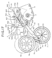
- the elevational wheel 7 shown in FIG. 17 to FIG. 19 comprises the aforementioned caster mechanism and is supported allowing free rotation through the caster mechanism, the straight traveling property of the machine body 1 may be deteriorated for such a reason that the elevational wheel 7 presses the soil forward in traveling in a field if the machine comprises such a caster mechanism.
- a grasp part 713 to be grasped by the operator in vertical adjustment of the elevational wheel 7 which will be described later in detail is attached in the vicinity of the rotary shaft 70k on the swing arm 70 as shown in FIG. 21 and FIG. 22, while a pin hole 710c for pivotally supporting the arm locks 710 is provided in a longitudinal intermediate portion of the swing arm 70 and a spring holder 70n for holding a forcing spring 70m is mounted on a base portion of the swing arm 70.
- the pair of right and left lock plates 720 are mounted on the frame 10, which is provided with the deep tillage corresponding grooves 720a, the standard tillage corresponding grooves 720b, the shallow tillage corresponding grooves 720c and the non-working corresponding grooves 720d.
- the pair of right and left arm locks 710 which are brought substantially into the form of cranks are arranged in the vicinity of the lock plates 720 as obvious from FIG. 21 and FIG. 23.
- the arm locks 710 has pin holes 710a formed in central portions thereof so that pivotal pins 710b are inserted between the pin holes 710a and the pin hole 710c of the swing arm 70, thereby being supported to be swingable frontward and rearward about the pivotal pins 710b with respect to the swing arm 70.
- the lock pins 700 selectively engaged in the respective grooves 720a to 720d of the lock plates 720 are projectingly provided on the top ends of the right and left arm locks 710, while a single adjusting lever 711 extending toward the elevational wheel 7 side is coupled and integrated with the other end of the each arm lock 710, so that an operating part 712 to be grasped by the operator in vertical adjustment of the elevational wheel 7 is mounted on a forward end of this lever 711.
- the forcing spring 70m is extended between the arm locks 710 and the spring holder 70n of the swing arm 70, for reliably engaging and holding the lock pins 700 in the respective grooves 720a to 720d with urging force of this spring 70m.
- the operator When the elevational wheel 7 is vertically adjusted in case of performing tilling depth adjustment by the rotary tiller 20, the operator simultaneously grasps the grasp part 713 of the swing arm 70 and the operating part 712 of the adjusting lever 711 provided on the arm locks 710 with a single hand.
- the arm locks 710 are swung frontward counterclockwise through the adjusting lever 711 about the pivotal pins 710b against the urging force of the forcing spring 70m as shown by phantom lines in FIG. 21 and the lock pins 700 engaged with any ones of the respective grooves 720a to 720d provided in the lock plates 720 separate from the engaging grooves, whereby the elevational wheel 7 can be vertically moved by moving the swing arm 70 about the pivotal pins 710b in the vertical direction in a state of grasping the grasp part 712 and the operating part 713 with a single hand.
- the lock pins 700 are engaged with any ones of the respective grooves 720a to 720d by the forcing spring 70m, and hence the tilling depth by the rotary tiller 20 can be simply and reliably adjusted in a desired depth.
- the operator can correctly confirm the tilling depth adjusted position by performing the tilling depth adjustment of the rotary tiller 20 in the vicinity of the rotary tiller 20.
- a grip 220 is mounted on the front part of the rotary cover 22 for vertically moving the whole of the rotary tiller 20 by grasping the grip 220.
- an exchange of the tillage tines 21 and a cleaning thereof can be readily performed by raising the rotary tiller 20 upward while grasping the grip 220 in case of replacing the tillage tines 21 or removing soil or grass entwined with the tillage tines 21, for example.
- the elevational wheel 7 can be readily moved to a position lower than the rotary tiller 20 by moving the elevational wheel 7 downward in a state of raising the whole of the rotary tiller 20 upward by grasping the grip 220.
- the clutch mechanism 49 comprises a swing arm 43 rotatably supporting a tension roller 34 through a rotary shaft 47 on a top end thereof while being supported a base part on the transmission case 5 allowing to swing backward and forward through a pivotal pin 48, a first spring 44 consisting of a torque spring wound on the outer periphery of the pivotal pin 48 on the base part of the swing arm 43, and an operation wire 45 having a longitudinal end coupled to the swing arm 43 and the other end coupled to a clutch lever 91 to be described later.
- a one leg of the first spring 44 is engaged with the swing arm 43 and the other leg thereof is engaged with a handle mounting boss part 500 provided on the transmission case 5 as described later, so that the swing arm 43 is forced to always swing forward by the first spring 44, and following this, the tension roller 34 is moved in a direction for loosening the belt 33 and held in an unclutched state.
- a second spring 46 of a conical shape is mounted on the top end of the operation wire 45 for coupling the operation wire 45 to the swing arm 43 therethrough, whereby the clutch lever 91 is turned from a clutched state to an unclutched state by these first and second springs 44 and 46.
- the handle 9 is formed substantially in a U-shape, by the pair of right and left handle base parts 901 whose forward base parts are coupled to and supported by the transmission case 5 and the loop-shaped grip part 90 continuously coupled to rear free ends of the respective handle base parts 901, as shown in FIG. 1.
- a cylindrical body 90a is provided on the front end of each handle base part 901 as shown in FIG. 24, so that this cylindrical body 90a is inserted in and coupled to the handle mounting boss part 500 provided on the transmission case 5 while a single positioning hole is provided in a longitudinal intermediate portion of each handle base part 901.
- a plurality of pins 90b inserted in this positioning hole are provided on the transmission case 5 on a circular arc about the boss part 500 so that the positioning hole is engaged with any one of the plurality of pins 90b, thereby each handle base part 901 is supported to be angle-changeable about the boss part 500.
- the clutch lever 91 for on-off operating the clutch mechanism 49 is supported to swing backward and forward in the vicinity of the grip part 90 in the handle base parts 901.
- This clutch lever 91 comprises right and left support parts 911 which are supported allowing free swing on the respective handle base parts 901 through pivotal pins 90c, and operating parts 912 which are coupled to free ends of the respective support parts 911 to extend in parallel with the grip part 90 of the handle 9, and a grasp part 913 to be grasped by the operator in a clutch operation is formed on the operating parts 912.
- the clutch lever 91 swings the swing arm 43 of the clutch mechanism 49 frontward by urging force of the first spring 44 when the same is positioned to be substantially upright with respect to the grip part 90 of the handle 9 as shown in solid lines of FIG. 1 and FIG. 2, and following this, the tension roller 34 held on the swing arm 43 is moved in the direction for loosening the belt 33 as shown by solid lines in FIG. 24, for attaining an unclutched state.
- the clutch lever 91 When the clutch lever 91 is positioned to be inclined rearward overlapping with the grip part 90 of the handle 9 as shown by phantom lines in FIG. 1 and FIG. 2, on the other hand, it swings the swing arm 43 rearward through the operation wire 45 against the urging force of the first spring 44 and following this, the tension roller 34 is brought into pressure contact with the belt 33 side and strains the same as shown by phantom lines in FIG. 24, whereby a clutched state is held.
- a non-overlapping part 100 not mutually overlapping is formed on at least one of the grip part 90 of the handle 9 and the operating parts 912 of the clutch lever 91. Namely, lengths of the operating parts 912 in the clutch lever 91 are shortened and the non-overlapping part 100 where the operating parts 912 do not overlap with the grip part 90 of the handle 9 is formed on a longitudinal intermediate portion of the grip part 90 of the handle 9 in the embodiment of FIG. 1 and FIG. 2.
- the clutch lever 91 is formed by a pair of independent first and second lever bodies 91A and 91B formed in substantial L-shapes on right and left having the support parts 911 and the operating parts 912 and a single connecting rod 91C which is extended between the support parts 911 of the lever bodies 91A and 91B, and the respective support parts 911 of the lever bodies 91A and 91B are supported by the respective handle base parts 901 through pivotal pins 90C, whereby the non-overlapping part 100 not overlapping with the operating parts of the respective lever bodies 91A and 91B is formed on the grip part 90 of the handle 9.
- the operator grasps the non-overlapping part 100 of the grip part 90 of the handle 9 with one hand while grasping with the other hand either one of the grip parts 913 provided on the operating parts 912 of the first and second lever bodies 91A and 91B for operating to swing the same rearward, thereby simultaneously swinging the other one of the lever bodies 91A and 91B through the connecting rod 91C, and following this, the clutch mechanism 49 can be operated into the aforementioned clutched state through the operation wire 45 coupled to one of the lever bodies 91A and 91B.
- the non-overlapping part 100 where the operating part 912 does not overlap with the grip part 90 of the handle 9 is formed on the longitudinal intermediate portion of the grip part 90 of the handle 9, whereby it is possible to reliably operate to swing the respective lever bodies 91A and 91B from unclutched states of being held substantially upright with respect to the grip part 90 to clutched states of being inclined rearward mutually overlapping with respect to the grip part 90 with the grasp parts 913 of the lever bodies 91A and 91B and the grip part 90 of the handle 9 not overlapping with each other and with no hindrance by the hand grasping the grip part 90 by operating to swing one of the lever bodies 91A and 91B while grasping the non-overlapping part 100 of the grip part 90.
- the clutch lever 91 is formed in a loop shape comprising right and left support parts 911 and an operating part 912 coupled to the free ends of these respective support parts 911 to extend in parallel with the grip part 90 of the handle 9 while the longitudinal central portion of the grip part 90 provided on the handle 9 is bent rearward in a U-shape in plan view, for forming the non-overlapping part 100 not overlapping with the operating part 912 of the clutch lever 91 by this bent part 902.
- the grip part 913 in the operating part 912 is continuously formed while its longitudinal central portion is separately extended frontward in a U-shape in plan view with respect to the grip part 90 of the handle 9, thereby forming on the grip part 90 the non-overlapping part 100 not overlapping with the portion of the grip part 913 extending frontward.
- the transmission case 5 and the rotary case 6 forming a power transmission part comprises right and left output shafts A forming the axle 4, a traveling side intermediate shaft B interlocking with the same through sprockets 29T and 9TB and a chain C1 and having a gear 39T, a first shifter shaft C which is axially displaced in association with an operation of a shift lever 93 and has a power transmission gear 15T to be axially displaced following this axial displacement, a second shifter shaft D having a shift fork 12TF which is axially displaced in association with the operation of the shift lever 93, an input shaft E from the engine 3, supporting a gear 12T to be axially displaced by the shift fork 12TF through a spline part ES, an intermediate shaft F having a fixed gear 38TB for transmitting traveling power and a slipping gear 38TA for transmitting rotary power, a rotary side intermediate shaft G having a gear 24T, and an output shaft H which is the rot
- the shift lever 93 is formed by an operation rod 93d for operating a speed change mechanism, a guide rod 93e bent in the form of a crank to be inserted in a guide plate 96 as described later, a discoidal connecting plate 93f integrally connecting these respective rods 93d and 93e with each other, and an operating rod 95 having an operating part 94 coupled to a free end of the guide rod 93e, as obvious from FIG. 29.
- the shift lever 93 is supported by the transmission case 5, in the manner that the operating rod 95 is extended to be inclined rear-upward through the guide rod 93e, as shown in FIG. 1 and FIG. 2.
- the operating part 94 of the operating rod 95 is positioned close to the grip part 90 of the handle 9, whereby the operator who operates the machine body 1 by gripping this grip part 90 can readily perform a speed change operation attaining excellent operability.
- the guide plate 96 in which the guide rod 93e of the shift lever 93 is inserted is arranged to incline oblique-downward toward the rear portion on a back upper portion of the transmission case 5 as shown in FIG. 1 and FIG. 2, and the guide plate 96 comprises first and second guide grooves 97 and 98 of vertical two stages and a communication groove 99 for making these respective guide grooves 97 and 98 communicate with each other, as shown in FIG. 30.
- the shift lever 93 swings about a base shaft part 93a while rotating about a perpendicular shaft part 93b perpendicular thereto as shown in FIG. 27, and moves along the respective guide grooves 97 and 98 of the guide plate 96, as shown in FIG. 28 and FIG. 30.
- the second shifter shaft D When the first shifter shaft C is in a position of neutral N, the second shifter shaft D is selectively moved to respective positions of the neutral N, rotary-off advance low speed F1 not rotating the rotor shaft 2, and rotary-on advance low speed Flon rotating the rotor shaft 2.
- the first shifter shaft C is selectively moved to respective positions of the neutral N, rotary-off reverse travel low speed R1 not rotating the rotary shaft 2, rotary-on reverse travel low speed Rlon rotating the rotary shaft 2, and rotary-off advance high speed F2 not rotating the rotor shaft 2.
- a portion 97a of the advance low speed Flon position in the first guide groove 97 is inclined oblique-downward.
- Positioning grooves CM and DM corresponding to respective shift stages are provided in the respective shifter shafts C and D as shown in FIG. 28, with which balls CB and DB pressed by coil springs CS and DS are engaged respectively as clearly shown in FIG. 31.
- a regulator BS interposed between the shifter shafts C and D is a regulator BS consisting of two regulating balls B1 and B2 for projecting the regulating ball B2 or B1 facing the shifter shaft D or C not moved into the groove DM or CM in the neutral N position at a time of moving one shifter shaft C or D and holding the shifter shaft D or C not moved in the neutral N position.
- the power transmission gear 15T supported on the first shifter shaft C forms a power transmission gear which is axially displaced following axial displacement of the first shifter shaft C for changing a transmission path for power taken out to the output side in response to the displaced position.
- the first shifter shaft C passes through a washer W1 engaged with a step part of the first shifter shaft C, the power transmission gear 15T, and a washer W2 and a stop ring 15TS placed on its end portion, and a stop pin 15TP is inserted into the stop ring 15TS and the first shifter shaft C.
- a projecting part of the stop pin 15TP is interposed between a pair of projections 51 and 52 projecting toward the inner part of the transmission case 5 as shown in FIG. 31 and FIG. 32, so that the stop ring 15TS as well as the first shifter shaft C do not rotate with rotation of the power transmission gear 15T.
- the power of the gear 12T is temporarily transmitted to the power transmission gear 15T and thereafter transmitted to the traveling side fixed gear 38TB, so that power of reverse rotation is transmitted toward the axle 4 side due to interposition of the single power transmission gear 15T with respect to the advance low speed F1.
- a receiving part 93g of the first shifter shaft C for the shift lever 93 may be annularly formed so that the first shifter shaft C is rotated along with the power transmission gear 15T as shown in FIG. 39.
- the position of Rlon of the guide groove 98 in the guide plate 96 may be omitted so that the shift lever 93 is stopped in the position of R1 for reverse-traveling the rotary tiller 20 at a low speed without driving the same, as shown by phantom lines in FIG. 30.
- a power transmission mechanism 170 having a differential mechanism 171 is arranged between the input shaft E and the right and left axles 4 in the interior of the transmission case 5.
- the differential mechanism 171 comprises a cylindrical primary side transmission member 81 integrating the sprocket 29T, discoidal secondary side transmission members 82 facing its right and left end surfaces, and movable bodies 80 provided between the primary side transmission member 81 and the secondary side transmission members 82, between the right and left output shafts A forming the axle 4 and the sprocket 29T, as shown in FIG. 40 and FIG. 41 in the concrete.
- These moving bodies 80 consist of balls made of steel which are rendered movable between engaging positions (FIG. 40) for engaging the primary side transmission member 81 and the secondary side transmission members 82 with each other and releasing positions (right side movable bodies in FIG. 41) for releasing this engagement, so that these movable bodies 80 retract from the engaging positions to the releasing positions to cut off power transmission when loads acting on the secondary side transmission members 82 are in excess of predetermined levels.
- through holes 81a for passing rightward and leftward (axially) are provided in a several portions, e.g., three portions, in the circumferential direction of the cylindrical primary side transmission member 81, and pairs of balls 80 forced rightward and leftward toward the exterior by coil springs 80a are arranged in the respective through holes 81a.
- Circular concave portions 81b are formed in right and left ends of the primary side transmission member 81, and the discoidal secondary side transmission members 82 for welding to fix the respective output shafts A forming the axle 4 are fit in the circular concave portions 81b respectively.
- tapered engaging concave portions 82a having tapered surfaces being inclined toward the circumferential direction for movably receiving the respective balls 80 are provided in surfaces of the respective secondary side transmission members 82 facing the circular concave portions 81b, as shown in FIG. 42 and FIG. 43. It is assumed that positions where the balls 80 are deeply in the engaging concave portions 82a are the engaging positions (FIG. 40), and positions where the balls 80 are shallowly in the engaging concave portions 82a to be flush with the planes of the secondary side transmission members 82, i.e., tapered portions are the releasing positions (the right side movable bodies in FIG. 41).
- numeral 80b denotes regulation pins for holding the balls 80 of one side of the right and left sides in the engaging positions when the balls 80 of the other sides are in releasing positions
- numeral 81c denotes insertion holes allowing sliding of the respective output shafts A
- numeral 82b denotes washers for sliding the secondary side transmission members 82
- numeral 82c denotes retaining rings.
- urging force may be attained by employing rubber bodies or by sealing air in the through holes 81a.
- close contact lengths of the coil springs 80a may be set in such relation that the balls 80 of one side are hold in the engaging positions when the balls 80 of the other side are in the releasing positions.
- the balls 80 smoothly separate since the engaging concave portions 82a present tapered surfaces. Further, the balls 80 perform power transmission until the same completely separate from the engaging concave portions 82a, whereby the right and left wheels 41 and 42 rotate at the same speed even if slight unequal force acts on the right and left wheels 41 and 42, and straight advancing property is not inhibited.
- each engaging concave portion 82a is provided with a tapered surface for guiding separation of the ball only on one side in the circumferential direction as shown in FIG. 43, the same may alternatively be inclined symmetrically on both sides in the circumferential direction so that tapered surfaces are provided on both portions of the engaging concave portion 82a as shown by phantom lines in FIG. 43.
- this power transmission mechanism 170 may be provided with a locking mechanism 180 along with the provision of the differential mechanism 171, as shown in FIG. 44 to FIG. 47.
- the differential mechanism 171 comprises a cylindrical primary side transmission member 81 which is integrally formed with a sprocket 29T connected to interlock with the input shaft E of the transmission case 5 on its outer peripheral part to be freely engaged with the transmission case 5 in a state of extending over the right and left axles 4 supported through ball bearings 5a and 5b, a pair of discoidal right and left secondary side transmission members 82 which are arranged on inner both sides of the same, and a plurality of shell-shaped movable bodies 80 which are interposed between the primary and secondary side transmission members 81 and 82.
- the respective movable bodies 80 are rendered movable in the range of engaging portions (indicated by the solid line in FIG. 44) for engaging the primary and secondary transmission members 81 and 82 with each other and transmitting power from the input shaft E to the respective axles 4, and releasing positions (indicated by the phantom line in the same figure) for releasing the engagement by the respective movable bodies 80 to cut off power transmission to the respective axles 4 when torques acting on the secondary side transmission members 82 are in excess of a predetermined level.
- a plurality of passing through holes 81a are formed rightward and leftward in the primary side transmission member 81 on the same circumferential line thereof for containing pairs of movable bodies 80 in the interior of the respective passing through holes 81a on right and left sides while coil springs 80a are interposed between the pairs of movable bodies 80 for forcing the respective movable bodies 80 toward the exterior of right and left with the coil springs 80a to be positioned in the engaging positions.
- the right and left secondary side transmission members 82 are engaged with spline grooves 41Sa and 42Sa provided on the respective axles 4 to be so supported that relative rotation of the secondary side transmission members 82 is impossible but only axial movement is allowed, while a plurality of engaging holes 82a which can be engaged with or disengaged from the respective movable bodies 80 are through-formed in these secondary side transmission members 82 in a plurality of portions on the same circumferential lines thereof.
- numeral 82c denotes retaining rings for the right and left secondary side transmission members 82.
- the locking mechanism 180 comprises regulation means 180a for holding engaging states and regulating relative rotation of the right and left axles 4 when the respective movable bodies 80 are positioned in the engaging positions and the primary and secondary side transmission members 81 and 82 are engaged with each other, and operation means 185 for operating the regulation means 180a.
- the operation means 185 comprises an operation arm 186 supported in the transmission case 5 to be swingable rightward and leftward through a pivotal pin 186a, an operating rod 187 which is coupled to an upper end of the arm 186 through a connecting pin 187a to be projected partially outward from the transmission case 5, and a coupling mechanism as described later coupling this operating rod 187 with a lock lever 102 provided on the handle 9.
- a presser 181 consisting of a roller is supported allowing free rotation on a lower side of the arm 186 through a support pin 181a, and a projection 182 regularly touching the presser 181 is provided on one secondary side transmission member 82 opposed to this presser 181.
- the coupling mechanism coupling the lock lever 102 of the handle 9 and the operating rod 187 is formed as follows: Namely, a mounting part 5c is provided on an outer side of the transmission case 5 in the vicinity of the operating rod 187 so that a lock arm 103 is supported on the mounting part 5c to be swingable rightward and leftward through a pivotal pin 103a and a projecting portion of the operating rod 187 from the transmission case 5 is coupled to a lower end of this lock arm 103 through the connecting pin 187a, while a wire receiver 103b is fixed to an upper side of the lock arm 103, as shown in FIG. 48.
- an operating wire 104 is coupled to the lock arm 103, and the operating wire 104 consists of an outer wire 104a and an inner wire 104b inserted in its interior, so that one longitudinal end of this outer wire 104a is supported by an outer receiver 105a mounted on a guide body 105 while a drum part 104c fixed to one longitudinal end of the inner wire 104b is supported by the wire receiver 103b fixed to the upper end portion of the lock arm 103.
- a bracket 106 is provided on a base side of the handle 9 for supporting the lock lever 102 allowing frontward and rearward swing on the bracket 106 through a pivotal shaft 102a and a spring receiver 102b for holding a spring 107 is provided on a lower end side of the lock lever 102, while an outer receiver 108 for the outer wire 104a in the wire 104 is mounted on the handle 9 for making the outer receiver 108 support the other longitudinal end of the outer wire 104a and the inner wire 104b is held by the spring 107.
- numeral 109 denotes a stopper of the lock lever 102.
- the operator turn-operates the handle 9 about the right side wheel 42 so that a large torque for straining rotation acts on the right side wheel 42 to which the torque is applied, whereby the right side movable body 80 on which this large torque acts retracts from the engaging position (indicated by the solid lines in FIG. 44) to the releasing position (indicated by the phantom line in the same figure).
- the lock lever 102 When the difference between the torques applied to the right and left axles 4 remarkably fluctuates due to the field conditions etc. or when ridge passage is performed, the lock lever 102 is operated to swing to lock the regulation means 180a of the lock mechanism 180, as shown in FIG. 45. Namely, the operating arm 186 is swung counterclockwise about its pivotal pin 186a through the operating rod 187 by operating to swing the lock lever 102 and operating to strain the inner wire 104b of the operating wire 104, for making the presser 181 supported on the operating arm 186 press the projection 182 provided on the left secondary side transmission member 82.
- this secondary side transmission member 82 is moved rightward along a spline groove 4a provided in the left axle 4 and following this, the left movable body 80 is pressed rightward, whereby the coil springs 80a interposed between the right and left movable bodies 80 are compressed.
- the compression of the coil springs 80a strengthens the force for engaging the right and left movable bodies 83 in the respective engaging holes 82a of the right and left side transmission members 82, i.e., the right and left movable bodies 80 are brought not to separate from the respective engaging holes 82a with slight torques, whereby the primary and secondary side transmission members 81 and 82 are held in locked states by the right and left movable bodies 83 and power transmission to the right and left axles 4 is performed together.
- the machine comprises the primary side transmission member 81, the secondary side transmission members 82, and the plurality of movable bodies 80 consisting of the balls interposed between these primary and secondary side transmission members 81 and 82 as the differential mechanism 171 similarly to the case of the aforementioned embodiment, and these respective movable bodies 80 engage the primary and secondary side transmission members 81 and 82 with each other to render the same movable in the range between the engaging positions (indicated by the solid line in FIG.
- washers 82b are provided on outer sides of the right and left secondary side transmission members 82 respectively, and retaining rings 82c are mounted on outer portions of the washers 82b.
- first and second engaging portions 183a and 183b consisting of through holes which are opposed to each other are formed on diametral inner peripheral sides of the right and left secondary side transmission members 82, while an engaging body 184 consisting of a pin which is projected into the first engaging portion 183a and which can be engaged with or disengaged from the second engaging portion 183b from the engaging portion 183a is mounted on an outer surface of an operating body 189 to be described later.
- the machine comprises a lock fork shaft 188 which is coupled to the lock lever 102 of the handle 9 through a coupling mechanism which is similar to the aforementioned one to be projected toward an exterior of the transmission case 5, while a fork shifter 188a is mounted on its top part and the operating body 189 having an engaging groove 189a in which the fork shifter 188a is engaged is slidably mounted on the left axle 41S.
- the right movable body 80 on which large torque acts retracts from the engaging position (indicated by the solid line in FIG. 46) to the releasing position (indicated by the phantom line in the same figure) so that power transmission from the primary side transmission member 81 to the right secondary transmission member 82 supplied with the torque is cut off for stopping rotation of the right axle 4 supplied with the torque, i.e., the right wheel 41 similarly to the aforementioned case, whereby right turn of the machine body 1 about the rotation-stopped right wheel 41 can be readily performed by only a handle operation.
- the right and left secondary side transmission members 82 i.e., the right and left axles 4
- the engaging body 184 are locked by the engaging body 184 not to be rotated relatively and power transmission from the primary side transmission member 81 to the right and left axles 4 is performed together, whereby neither locking nor unlocking of the primary and secondary transmission members 81 and 82 not intended by the operator is frequently performed but a stable straight traveling property of the machine body 1 can be ensured even if the difference between the torques applied to the right and left axles 4 remarkably fluctuates, while ridge passage of the machine body 1 can also be reliably performed.
- right and left sides of the right and left secondary side transmission members 82 may be inserted in and engaged with the respective engaging portions 183a and 183b.
- a levelling rake 150 for levelling cultivated soil by the rotary tiller 20 on a lower position of the handle 9 at the back of the traveling wheels 40 in the aforementioned managing machine, as shown in FIG. 50.
- a bracket 151 is fixedly provided on a front lower portion of the handle 9 for making the bracket 151 vertically swingably support a cylindrical body 152 along the vertical direction by a pivotal shaft 153, while a support rod 154 extending upward from the levelling rake 150 is supported on the cylindrical body 152 to be vertically adjustable by an adjusting bolt 155.
- a mounting part 150a is provided on a rear portion of the transmission case 5 for making this mounting part 150a support a crank arm 157 allowing frontward and rearward swing through a pivotal shaft 156, and an end of this crank arm 157 and an operating lever 150b mounted on the handle 9 are coupled with each other by an operating wire 158, while a tension spring 159 is extended between the crank arm 157 and the support rod 154 of the levelling rake 150.
- the support rod 154 and the cylindrical body 152 are held in substantially vertical position as shown in the same figure so that the levelling rake 150 is positioned at the back of the traveling wheels 40, whereby soil cultivated by the rotary tiller 20 can be uniformly levelled by the levelling rake 150 even if the same is trodden by the traveling wheels 40.
- the cylindrical body 152 can be retracted rearward about the pivotal shaft 153 along with the levelling rake 150 and the support rod 154 in groove opening in the tilling operation by swinging the crank arm 157 counterclockwise about the pivotal shaft 156 by an operation of the operating lever 150b, and following this, by weakening the tension of the tension spring 159, the groove opening operation can be readily performed with no hindrance by the levelling rake 150 at the time of groove opening.
- the present invention is useful as an agricultural machine performing a tilling operation, various management operations in agricultural operations and the like, and can be suitably employed in particular as a walking type agricultural machine prepared by mounting a rotary tiller etc. on a rotor shaft for performing the tilling operation etc.
Landscapes
- Life Sciences & Earth Sciences (AREA)
- Engineering & Computer Science (AREA)
- Mechanical Engineering (AREA)
- Soil Sciences (AREA)
- Environmental Sciences (AREA)
- Soil Working Implements (AREA)
Applications Claiming Priority (28)
| Application Number | Priority Date | Filing Date | Title |
|---|---|---|---|
| JP125489/95 | 1995-05-24 | ||
| JP7125485A JP3015821B2 (ja) | 1995-05-24 | 1995-05-24 | 農作業機 |
| JP12548995 | 1995-05-24 | ||
| JP12548695 | 1995-05-24 | ||
| JP12548795 | 1995-05-24 | ||
| JP125488/95 | 1995-05-24 | ||
| JP12548895A JP3678458B2 (ja) | 1995-05-24 | 1995-05-24 | 農作業機 |
| JP125485/95 | 1995-05-24 | ||
| JP12548595 | 1995-05-24 | ||
| JP12548895 | 1995-05-24 | ||
| JP12549095A JP3603192B2 (ja) | 1995-05-24 | 1995-05-24 | 農作業機の変速装置 |
| JP12549095 | 1995-05-24 | ||
| JP07125486A JP3089279B2 (ja) | 1995-05-24 | 1995-05-24 | 農作業機 |
| JP125486/95 | 1995-05-24 | ||
| JP125490/95 | 1995-05-24 | ||
| JP12548995A JP3963493B2 (ja) | 1995-05-24 | 1995-05-24 | 歩行型の農作業機 |
| JP125487/95 | 1995-05-24 | ||
| JP12548795A JP3160698B2 (ja) | 1995-05-24 | 1995-05-24 | 農作業機 |
| JP8693096 | 1996-04-09 | ||
| JP8693196A JPH09272458A (ja) | 1996-04-09 | 1996-04-09 | 農作業機 |
| JP8693196 | 1996-04-09 | ||
| JP86931/96 | 1996-04-09 | ||
| JP8693096A JPH09271204A (ja) | 1996-04-09 | 1996-04-09 | 農作業機 |
| JP86930/96 | 1996-04-09 | ||
| JP9418796 | 1996-04-16 | ||
| JP94187/96 | 1996-04-16 | ||
| JP09418796A JP3610443B2 (ja) | 1996-04-16 | 1996-04-16 | 農作業機 |
| PCT/JP1996/001405 WO1996037092A1 (fr) | 1995-05-24 | 1996-05-24 | Machine agricole |
Publications (3)
| Publication Number | Publication Date |
|---|---|
| EP0774200A1 EP0774200A1 (en) | 1997-05-21 |
| EP0774200A4 EP0774200A4 (en) | 2000-04-05 |
| EP0774200B1 true EP0774200B1 (en) | 2003-07-23 |
Family
ID=27577239
Family Applications (1)
| Application Number | Title | Priority Date | Filing Date |
|---|---|---|---|
| EP96914439A Expired - Lifetime EP0774200B1 (en) | 1995-05-24 | 1996-05-24 | Farm working machine |
Country Status (4)
| Country | Link |
|---|---|
| EP (1) | EP0774200B1 (es) |
| DE (1) | DE69629163T2 (es) |
| ES (1) | ES2203695T3 (es) |
| WO (1) | WO1996037092A1 (es) |
Cited By (1)
| Publication number | Priority date | Publication date | Assignee | Title |
|---|---|---|---|---|
| CN104067717A (zh) * | 2014-06-23 | 2014-10-01 | 重庆嘉木机械有限公司 | 一种便携式微耕机后轮总成与发动机布置结构 |
Families Citing this family (8)
| Publication number | Priority date | Publication date | Assignee | Title |
|---|---|---|---|---|
| JP3839769B2 (ja) * | 2002-01-16 | 2006-11-01 | 本田技研工業株式会社 | 歩行型作業機 |
| US7866409B2 (en) | 2007-09-06 | 2011-01-11 | Honda Motor Co., Ltd. | Tilling machine transport and storage apparatuses and methods |
| JP6233140B2 (ja) * | 2014-03-28 | 2017-11-22 | 井関農機株式会社 | 歩行型耕耘機 |
| CN104054423B (zh) * | 2014-06-23 | 2015-12-09 | 重庆嘉木机械有限公司 | 一种微耕机发动机及螺杆传动箱安装结构 |
| CN104054424B (zh) * | 2014-06-23 | 2016-04-20 | 重庆嘉木机械有限公司 | 一种便携式微耕机手把座与发动机及传动箱布置结构 |
| CN104067718B (zh) * | 2014-06-23 | 2015-12-09 | 重庆嘉木机械有限公司 | 一种便携式微耕机螺杆传动箱与机架总成 |
| CN104541621B (zh) * | 2014-12-03 | 2016-07-06 | 宁波大叶园林设备有限公司 | 改进的带有燃气燃料罐的发动机的旋耕机 |
| EP4140268A1 (de) * | 2021-08-26 | 2023-03-01 | Rapid Technic AG | Umkehrfräse |
Family Cites Families (10)
| Publication number | Priority date | Publication date | Assignee | Title |
|---|---|---|---|---|
| US2827842A (en) * | 1954-05-05 | 1958-03-25 | Fmc Corp | Agricultural machine |
| NL302001A (es) * | 1963-09-18 | |||
| US3986573A (en) * | 1975-05-29 | 1976-10-19 | Alderson Robert C | Utility tractor |
| US4214632A (en) * | 1978-02-08 | 1980-07-29 | Brookshier Ernest L | Soil tilling machine having apparatus for automatic negative braking and drive control |
| US4249612A (en) * | 1979-03-09 | 1981-02-10 | Joseph Lajack | Rotary tiller and attachment therefor |
| FR2470520A1 (fr) * | 1979-12-03 | 1981-06-12 | Sodiplay Sa | Appareil de motoculture |
| US4519459A (en) * | 1983-03-31 | 1985-05-28 | Magna American Corporation | Power drive rear tine tiller with reversing gear transmission for the tines |
| US4699219A (en) * | 1984-04-02 | 1987-10-13 | Garden Way Incorporated | Cultivator drag bar and mounting therefor |
| JPH0337361Y2 (es) * | 1984-12-20 | 1991-08-07 | ||
| US5146997A (en) * | 1991-12-16 | 1992-09-15 | Korin Mark R | Lake weed removing apparatus |
-
1996
- 1996-05-24 ES ES96914439T patent/ES2203695T3/es not_active Expired - Lifetime
- 1996-05-24 DE DE69629163T patent/DE69629163T2/de not_active Expired - Lifetime
- 1996-05-24 EP EP96914439A patent/EP0774200B1/en not_active Expired - Lifetime
- 1996-05-24 WO PCT/JP1996/001405 patent/WO1996037092A1/ja active IP Right Grant
Cited By (2)
| Publication number | Priority date | Publication date | Assignee | Title |
|---|---|---|---|---|
| CN104067717A (zh) * | 2014-06-23 | 2014-10-01 | 重庆嘉木机械有限公司 | 一种便携式微耕机后轮总成与发动机布置结构 |
| CN104067717B (zh) * | 2014-06-23 | 2015-11-18 | 重庆嘉木机械有限公司 | 一种便携式微耕机后轮总成与发动机布置结构 |
Also Published As
| Publication number | Publication date |
|---|---|
| EP0774200A4 (en) | 2000-04-05 |
| DE69629163D1 (de) | 2003-08-28 |
| WO1996037092A1 (fr) | 1996-11-28 |
| ES2203695T3 (es) | 2004-04-16 |
| DE69629163T2 (de) | 2004-04-15 |
| EP0774200A1 (en) | 1997-05-21 |
Similar Documents
| Publication | Publication Date | Title |
|---|---|---|
| EP0774200B1 (en) | Farm working machine | |
| JP3739513B2 (ja) | 歩行型農作業機 | |
| JP4408336B2 (ja) | 管理機 | |
| JP3963493B2 (ja) | 歩行型の農作業機 | |
| JP2004008082A (ja) | 簡易乗用管理作業機 | |
| JP3883542B2 (ja) | 農作業機 | |
| JPH08320055A (ja) | 農作業機の変速装置 | |
| JP4488518B2 (ja) | 乗用型田植機 | |
| JP4259372B2 (ja) | 移動農機 | |
| JP3742175B2 (ja) | 歩行型農作業機 | |
| JP3564617B2 (ja) | 農作業機 | |
| JPH08317706A (ja) | 農作業機 | |
| JP3678458B2 (ja) | 農作業機 | |
| JPH08317704A (ja) | 農作業機 | |
| JP3690071B2 (ja) | ロータリ耕耘具の防護装置 | |
| JP3089279B2 (ja) | 農作業機 | |
| JPH10226370A (ja) | 歩行型農作業機 | |
| JP4039959B2 (ja) | 乗用型田植機の予備苗のせ台構造 | |
| JP3509921B2 (ja) | 乗用管理機 | |
| JP2005313739A (ja) | 農作業車 | |
| JP4626147B2 (ja) | 田植機 | |
| JP3111180B2 (ja) | 草刈機 | |
| JP2000188902A (ja) | 歩行型管理作業耕耘装置 | |
| JP2002345304A (ja) | 農作業機 | |
| JPH11318130A (ja) | 乗用田植機 |
Legal Events
| Date | Code | Title | Description |
|---|---|---|---|
| PUAI | Public reference made under article 153(3) epc to a published international application that has entered the european phase |
Free format text: ORIGINAL CODE: 0009012 |
|
| 17P | Request for examination filed |
Effective date: 19961107 |
|
| AK | Designated contracting states |
Kind code of ref document: A1 Designated state(s): DE ES FR IT |
|
| A4 | Supplementary search report drawn up and despatched |
Effective date: 20000218 |
|
| AK | Designated contracting states |
Kind code of ref document: A4 Designated state(s): DE ES FR IT |
|
| RIC1 | Information provided on ipc code assigned before grant |
Free format text: 7A 01B 33/02 A, 7A 01B 51/02 B |
|
| 17Q | First examination report despatched |
Effective date: 20020531 |
|
| GRAH | Despatch of communication of intention to grant a patent |
Free format text: ORIGINAL CODE: EPIDOS IGRA |
|
| GRAH | Despatch of communication of intention to grant a patent |
Free format text: ORIGINAL CODE: EPIDOS IGRA |
|
| GRAA | (expected) grant |
Free format text: ORIGINAL CODE: 0009210 |
|
| AK | Designated contracting states |
Designated state(s): DE ES FR IT |
|
| REF | Corresponds to: |
Ref document number: 69629163 Country of ref document: DE Date of ref document: 20030828 Kind code of ref document: P |
|
| ET | Fr: translation filed | ||
| REG | Reference to a national code |
Ref country code: ES Ref legal event code: FG2A Ref document number: 2203695 Country of ref document: ES Kind code of ref document: T3 |
|
| PLBE | No opposition filed within time limit |
Free format text: ORIGINAL CODE: 0009261 |
|
| STAA | Information on the status of an ep patent application or granted ep patent |
Free format text: STATUS: NO OPPOSITION FILED WITHIN TIME LIMIT |
|
| 26N | No opposition filed |
Effective date: 20040426 |
|
| PGFP | Annual fee paid to national office [announced via postgrant information from national office to epo] |
Ref country code: FR Payment date: 20100525 Year of fee payment: 15 Ref country code: ES Payment date: 20100611 Year of fee payment: 15 |
|
| PGFP | Annual fee paid to national office [announced via postgrant information from national office to epo] |
Ref country code: IT Payment date: 20100517 Year of fee payment: 15 Ref country code: DE Payment date: 20100519 Year of fee payment: 15 |
|
| REG | Reference to a national code |
Ref country code: FR Ref legal event code: TP |
|
| REG | Reference to a national code |
Ref country code: DE Ref legal event code: R119 Ref document number: 69629163 Country of ref document: DE |
|
| REG | Reference to a national code |
Ref country code: DE Ref legal event code: R119 Ref document number: 69629163 Country of ref document: DE |
|
| REG | Reference to a national code |
Ref country code: FR Ref legal event code: ST Effective date: 20120131 |
|
| PG25 | Lapsed in a contracting state [announced via postgrant information from national office to epo] |
Ref country code: IT Free format text: LAPSE BECAUSE OF NON-PAYMENT OF DUE FEES Effective date: 20110524 |
|
| PG25 | Lapsed in a contracting state [announced via postgrant information from national office to epo] |
Ref country code: FR Free format text: LAPSE BECAUSE OF NON-PAYMENT OF DUE FEES Effective date: 20110531 |
|
| REG | Reference to a national code |
Ref country code: ES Ref legal event code: FD2A Effective date: 20120717 |
|
| PG25 | Lapsed in a contracting state [announced via postgrant information from national office to epo] |
Ref country code: ES Free format text: LAPSE BECAUSE OF NON-PAYMENT OF DUE FEES Effective date: 20110525 |
|
| PG25 | Lapsed in a contracting state [announced via postgrant information from national office to epo] |
Ref country code: DE Free format text: LAPSE BECAUSE OF NON-PAYMENT OF DUE FEES Effective date: 20111130 |