EP0774067B1 - Distributeur a tiroir cylindrique de mini-servomecanisme actionne par electro-aimant - Google Patents
Distributeur a tiroir cylindrique de mini-servomecanisme actionne par electro-aimant Download PDFInfo
- Publication number
- EP0774067B1 EP0774067B1 EP19960913222 EP96913222A EP0774067B1 EP 0774067 B1 EP0774067 B1 EP 0774067B1 EP 19960913222 EP19960913222 EP 19960913222 EP 96913222 A EP96913222 A EP 96913222A EP 0774067 B1 EP0774067 B1 EP 0774067B1
- Authority
- EP
- European Patent Office
- Prior art keywords
- valve
- spool
- high pressure
- fluid communication
- actuator
- Prior art date
- Legal status (The legal status is an assumption and is not a legal conclusion. Google has not performed a legal analysis and makes no representation as to the accuracy of the status listed.)
- Expired - Lifetime
Links
- 239000012530 fluid Substances 0.000 claims description 45
- 239000000446 fuel Substances 0.000 claims description 41
- 238000007789 sealing Methods 0.000 claims description 34
- 238000004891 communication Methods 0.000 claims description 21
- 239000003921 oil Substances 0.000 description 18
- 238000002347 injection Methods 0.000 description 12
- 239000007924 injection Substances 0.000 description 12
- 238000002485 combustion reaction Methods 0.000 description 6
- 239000010687 lubricating oil Substances 0.000 description 2
- 238000004519 manufacturing process Methods 0.000 description 2
- 238000012986 modification Methods 0.000 description 2
- 230000004048 modification Effects 0.000 description 2
- 239000010705 motor oil Substances 0.000 description 2
- 230000006835 compression Effects 0.000 description 1
- 238000007906 compression Methods 0.000 description 1
- 230000007423 decrease Effects 0.000 description 1
- 230000001419 dependent effect Effects 0.000 description 1
- 238000010586 diagram Methods 0.000 description 1
- -1 e.g. Substances 0.000 description 1
- 239000002828 fuel tank Substances 0.000 description 1
- 230000036316 preload Effects 0.000 description 1
- 238000004804 winding Methods 0.000 description 1
Images


Classifications
-
- F—MECHANICAL ENGINEERING; LIGHTING; HEATING; WEAPONS; BLASTING
- F02—COMBUSTION ENGINES; HOT-GAS OR COMBUSTION-PRODUCT ENGINE PLANTS
- F02M—SUPPLYING COMBUSTION ENGINES IN GENERAL WITH COMBUSTIBLE MIXTURES OR CONSTITUENTS THEREOF
- F02M63/00—Other fuel-injection apparatus having pertinent characteristics not provided for in groups F02M39/00 - F02M57/00 or F02M67/00; Details, component parts, or accessories of fuel-injection apparatus, not provided for in, or of interest apart from, the apparatus of groups F02M39/00 - F02M61/00 or F02M67/00; Combination of fuel pump with other devices, e.g. lubricating oil pump
- F02M63/0012—Valves
- F02M63/0014—Valves characterised by the valve actuating means
- F02M63/0015—Valves characterised by the valve actuating means electrical, e.g. using solenoid
- F02M63/0017—Valves characterised by the valve actuating means electrical, e.g. using solenoid using electromagnetic operating means
-
- F—MECHANICAL ENGINEERING; LIGHTING; HEATING; WEAPONS; BLASTING
- F02—COMBUSTION ENGINES; HOT-GAS OR COMBUSTION-PRODUCT ENGINE PLANTS
- F02M—SUPPLYING COMBUSTION ENGINES IN GENERAL WITH COMBUSTIBLE MIXTURES OR CONSTITUENTS THEREOF
- F02M47/00—Fuel-injection apparatus operated cyclically with fuel-injection valves actuated by fluid pressure
- F02M47/02—Fuel-injection apparatus operated cyclically with fuel-injection valves actuated by fluid pressure of accumulator-injector type, i.e. having fuel pressure of accumulator tending to open, and fuel pressure in other chamber tending to close, injection valves and having means for periodically releasing that closing pressure
- F02M47/025—Hydraulically actuated valves draining the chamber to release the closing pressure
-
- F—MECHANICAL ENGINEERING; LIGHTING; HEATING; WEAPONS; BLASTING
- F02—COMBUSTION ENGINES; HOT-GAS OR COMBUSTION-PRODUCT ENGINE PLANTS
- F02M—SUPPLYING COMBUSTION ENGINES IN GENERAL WITH COMBUSTIBLE MIXTURES OR CONSTITUENTS THEREOF
- F02M47/00—Fuel-injection apparatus operated cyclically with fuel-injection valves actuated by fluid pressure
- F02M47/02—Fuel-injection apparatus operated cyclically with fuel-injection valves actuated by fluid pressure of accumulator-injector type, i.e. having fuel pressure of accumulator tending to open, and fuel pressure in other chamber tending to close, injection valves and having means for periodically releasing that closing pressure
- F02M47/027—Electrically actuated valves draining the chamber to release the closing pressure
-
- F—MECHANICAL ENGINEERING; LIGHTING; HEATING; WEAPONS; BLASTING
- F02—COMBUSTION ENGINES; HOT-GAS OR COMBUSTION-PRODUCT ENGINE PLANTS
- F02M—SUPPLYING COMBUSTION ENGINES IN GENERAL WITH COMBUSTIBLE MIXTURES OR CONSTITUENTS THEREOF
- F02M57/00—Fuel-injectors combined or associated with other devices
- F02M57/02—Injectors structurally combined with fuel-injection pumps
- F02M57/022—Injectors structurally combined with fuel-injection pumps characterised by the pump drive
- F02M57/025—Injectors structurally combined with fuel-injection pumps characterised by the pump drive hydraulic, e.g. with pressure amplification
-
- F—MECHANICAL ENGINEERING; LIGHTING; HEATING; WEAPONS; BLASTING
- F02—COMBUSTION ENGINES; HOT-GAS OR COMBUSTION-PRODUCT ENGINE PLANTS
- F02M—SUPPLYING COMBUSTION ENGINES IN GENERAL WITH COMBUSTIBLE MIXTURES OR CONSTITUENTS THEREOF
- F02M59/00—Pumps specially adapted for fuel-injection and not provided for in groups F02M39/00 -F02M57/00, e.g. rotary cylinder-block type of pumps
- F02M59/02—Pumps specially adapted for fuel-injection and not provided for in groups F02M39/00 -F02M57/00, e.g. rotary cylinder-block type of pumps of reciprocating-piston or reciprocating-cylinder type
- F02M59/10—Pumps specially adapted for fuel-injection and not provided for in groups F02M39/00 -F02M57/00, e.g. rotary cylinder-block type of pumps of reciprocating-piston or reciprocating-cylinder type characterised by the piston-drive
- F02M59/105—Pumps specially adapted for fuel-injection and not provided for in groups F02M39/00 -F02M57/00, e.g. rotary cylinder-block type of pumps of reciprocating-piston or reciprocating-cylinder type characterised by the piston-drive hydraulic drive
-
- F—MECHANICAL ENGINEERING; LIGHTING; HEATING; WEAPONS; BLASTING
- F02—COMBUSTION ENGINES; HOT-GAS OR COMBUSTION-PRODUCT ENGINE PLANTS
- F02M—SUPPLYING COMBUSTION ENGINES IN GENERAL WITH COMBUSTIBLE MIXTURES OR CONSTITUENTS THEREOF
- F02M59/00—Pumps specially adapted for fuel-injection and not provided for in groups F02M39/00 -F02M57/00, e.g. rotary cylinder-block type of pumps
- F02M59/44—Details, components parts, or accessories not provided for in, or of interest apart from, the apparatus of groups F02M59/02 - F02M59/42; Pumps having transducers, e.g. to measure displacement of pump rack or piston
- F02M59/46—Valves
- F02M59/466—Electrically operated valves, e.g. using electromagnetic or piezoelectric operating means
-
- F—MECHANICAL ENGINEERING; LIGHTING; HEATING; WEAPONS; BLASTING
- F02—COMBUSTION ENGINES; HOT-GAS OR COMBUSTION-PRODUCT ENGINE PLANTS
- F02M—SUPPLYING COMBUSTION ENGINES IN GENERAL WITH COMBUSTIBLE MIXTURES OR CONSTITUENTS THEREOF
- F02M63/00—Other fuel-injection apparatus having pertinent characteristics not provided for in groups F02M39/00 - F02M57/00 or F02M67/00; Details, component parts, or accessories of fuel-injection apparatus, not provided for in, or of interest apart from, the apparatus of groups F02M39/00 - F02M61/00 or F02M67/00; Combination of fuel pump with other devices, e.g. lubricating oil pump
- F02M63/0012—Valves
- F02M63/0014—Valves characterised by the valve actuating means
- F02M63/0028—Valves characterised by the valve actuating means hydraulic
- F02M63/0029—Valves characterised by the valve actuating means hydraulic using a pilot valve controlling a hydraulic chamber
-
- F—MECHANICAL ENGINEERING; LIGHTING; HEATING; WEAPONS; BLASTING
- F02—COMBUSTION ENGINES; HOT-GAS OR COMBUSTION-PRODUCT ENGINE PLANTS
- F02M—SUPPLYING COMBUSTION ENGINES IN GENERAL WITH COMBUSTIBLE MIXTURES OR CONSTITUENTS THEREOF
- F02M63/00—Other fuel-injection apparatus having pertinent characteristics not provided for in groups F02M39/00 - F02M57/00 or F02M67/00; Details, component parts, or accessories of fuel-injection apparatus, not provided for in, or of interest apart from, the apparatus of groups F02M39/00 - F02M61/00 or F02M67/00; Combination of fuel pump with other devices, e.g. lubricating oil pump
- F02M63/0012—Valves
- F02M63/0031—Valves characterized by the type of valves, e.g. special valve member details, valve seat details, valve housing details
- F02M63/004—Sliding valves, e.g. spool valves, i.e. whereby the closing member has a sliding movement along a seat for opening and closing
-
- F—MECHANICAL ENGINEERING; LIGHTING; HEATING; WEAPONS; BLASTING
- F02—COMBUSTION ENGINES; HOT-GAS OR COMBUSTION-PRODUCT ENGINE PLANTS
- F02M—SUPPLYING COMBUSTION ENGINES IN GENERAL WITH COMBUSTIBLE MIXTURES OR CONSTITUENTS THEREOF
- F02M63/00—Other fuel-injection apparatus having pertinent characteristics not provided for in groups F02M39/00 - F02M57/00 or F02M67/00; Details, component parts, or accessories of fuel-injection apparatus, not provided for in, or of interest apart from, the apparatus of groups F02M39/00 - F02M61/00 or F02M67/00; Combination of fuel pump with other devices, e.g. lubricating oil pump
- F02M63/0012—Valves
- F02M63/0031—Valves characterized by the type of valves, e.g. special valve member details, valve seat details, valve housing details
- F02M63/0045—Three-way valves
-
- F—MECHANICAL ENGINEERING; LIGHTING; HEATING; WEAPONS; BLASTING
- F02—COMBUSTION ENGINES; HOT-GAS OR COMBUSTION-PRODUCT ENGINE PLANTS
- F02M—SUPPLYING COMBUSTION ENGINES IN GENERAL WITH COMBUSTIBLE MIXTURES OR CONSTITUENTS THEREOF
- F02M2200/00—Details of fuel-injection apparatus, not otherwise provided for
- F02M2200/21—Fuel-injection apparatus with piezoelectric or magnetostrictive elements
-
- Y—GENERAL TAGGING OF NEW TECHNOLOGICAL DEVELOPMENTS; GENERAL TAGGING OF CROSS-SECTIONAL TECHNOLOGIES SPANNING OVER SEVERAL SECTIONS OF THE IPC; TECHNICAL SUBJECTS COVERED BY FORMER USPC CROSS-REFERENCE ART COLLECTIONS [XRACs] AND DIGESTS
- Y10—TECHNICAL SUBJECTS COVERED BY FORMER USPC
- Y10T—TECHNICAL SUBJECTS COVERED BY FORMER US CLASSIFICATION
- Y10T137/00—Fluid handling
- Y10T137/8593—Systems
- Y10T137/86493—Multi-way valve unit
- Y10T137/86574—Supply and exhaust
- Y10T137/86582—Pilot-actuated
- Y10T137/86614—Electric
Definitions
- the present invention relates generally to fluid valves, and more particularly to an actuable valve for operating a fluid control device, such as a fuel injector or an engine valve.
- Actuation valves are often employed to operate fluid control devices, for example fuel injectors used in internal combustion engines.
- One type of actuation valve includes a solenoid and a double-acting poppet valve which controls the admittance of pressurized fluid, e.g., engine oil, into an intensifier chamber.
- pressurized fluid acts against the intensifier piston so that the piston is displaced in a direction which causes fuel located in a high pressure chamber to be pressurized.
- the pressurized fuel in turn acts against a spring-biased check and, when the pressure of the fuel rises to a high enough level, the check is opened and the fuel is injected into an associated combustion chamber.
- US-A-5,096,121 discloses a two-stage, hydraulic, electronic unit fuel injector powered by lubricating oil from the engine crankcase and including a housing, a pilot valve disposed in the housing and connected to an electronically-controlled solenoid for movement with the armature thereof, a slidable poppet valve disposed in the housing beneath the pilot valve and controlled by the action of the pilot valve, and a fixed intensifier dump valve disposed within the poppet valve.
- An intensifier piston controlled by the action of the poppet valve, is disposed within the housing below the intensifier dump valve which upon receiving high pressure fluid, in this case, lubricating oil, is forced downwardly to inject fuel received in the lower end of the injector from a common rail out of the injector tip under very high pressure.
- Both the pilot valve and the poppet valve are provided with valving arrangements, in the form of valve seats, internal passages, and registering annular grooves to provide and relieve the pressure acting respectively on the poppet valve and on the intensifier piston at various times during the injection cycle.
- the pilot valve Prior to the start of injection, the pilot valve provides high pressure to the top of the poppet valve forcing the poppet against its seat, relieving the pressure on the intensifier piston by dumping the pressurized oil externally of the injector onto the top of the cylinder head.
- the pilot valve moves to start injection, it closes the high pressure source and dumps the pressurized oil above the poppet externally so that differential pressure acting upwardly on the poppet valve opens the poppet and exposes the intensifier piston to the high pressure source, causing injection.
- the pilot valve closes, forcing the poppet down against its seat and dumping the oil from the intensifier piston causing injection to end.
- a valve according to the present invention is capable of fast operation and is desirably small and light in weight as compared with prior valves.
- a valve is provided as set forth in claim 1. Preferred embodiments of the invention may be gathered from the dependent claims.
- the force of the actuator utilized in the present invention acts against a low mass valve element and does not act directly against a spring force. Because of these factors, the actuator can be made desirably small and light in weight.
- a hydraulically-actuated, electronically-controlled unit injector (HEUI) system 10 includes a transfer pump 12 which receives fuel from a fuel tank 14 and a filter 16 and delivers same at a relatively low pressure of, for example, about 0.414 MPa (60 p.s.i.), to fuel injectors 18 via fuel rail lines or conduits 20.
- An actuating fluid such as engine oil supplied from an engine sump, is pressurized by a pump 22 to a nominal intermediate pressure of, for example, 20.7 MPa (3,000 p.s.i.).
- a rail pressure control valve 24 may be provided to modulate the oil pressure provided over oil rail lines or conduits 26 to the injectors 18 in dependence upon the level of a signal supplied by an electronic engine controller 28.
- the fuel injectors 18 inject fuel at a high pressure of, for example, 138 MPa (20,000 p.s.i.) or greater, into associated combustion chambers or cylinders (not shown) of an internal combustion engine. While six fuel injectors 18 are shown in Fig. 1, it should be noted that a different number of fuel injectors may alternatively be used to inject fuel into a like number of associated combustion chambers. Also, the engine with which the fuel injection system 10 may be used may comprise a diesel-cycle engine, an ignition assisted engine or any other type of engine where it is necessary or desirable to inject fuel therein.
- the fuel injection system 10 of Fig. 1 may be modified by the addition of separate fuel and/or oil supply lines extending between the pumps 12 and 22 and each injector 18.
- fuel or any other fluid may be used as the actuating fluid and/or the timing and injection duration of the injectors may be controlled by mechanical or hydraulic apparatus rather than the engine controller 28, if desired.
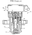
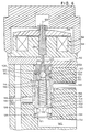
- Figs. 2A, 2B and 3 illustrate a prior art fuel injector 18 which is usable with the fuel injection system 10 of Fig. 1.
- the fuel injector is disclosed in Glassey U.S. Patent No. 5,191,867 and reference should be had thereto for a full description of the injector.
- the fuel injector 18 includes an actuator and valve assembly 28, a body assembly 30, a barrel assembly 32 and a nozzle and tip assembly 34.
- the actuator and valve assembly 28 acts as a means for selectively communicating either relatively high pressure oil or low pressure oil to an intensifier piston 35.
- the actuator and valve assembly 29 includes an actuator 36, preferably in the form of a solenoid assembly, and a valve 38, preferably in the form of a poppet valve.
- the solenoid assembly 36 includes a fixed stator assembly 40 and a movable armature 42 coupled to a poppet 34 of the valve 38.
- a spring 46 biases the poppet 34 so that a sealing surface 48 of the poppet 34 is disposed in sealing contact with a valve seat 50. Consequently, an oil inlet passage 52 is taken out of fluid communication with an intensifier chamber 54.
- fuel injection is to commence the actuator 36 is energized by an electrical control signal developed by the engine controller 28, causing the poppet 34 to be displaced upwardly and spacing the sealing surface 48 from the valve seat 50. Pressurized oil then flows from the oil inlet passage 52 into the intensifier chamber 54.
- the intensifier piston 35 is displaced downwardly, thereby pressurizing fuel drawn into a high pressure chamber 56 through a fuel inlet 58 and a check valve 60.
- the pressurized fuel is supplied to a check bore 62 through passages 64.
- An elongate check 66 is disposed in the check bore 62 and, as seen most clearly in Fig. 2B, includes a sealing tip 68 disposed at a first end portion 70 and an enlarged plate or head 72 disposed at a second end portion 74.
- a spring 76 biases the tip 68 against a valve seat 78 to isolate the check bore 62 from one or more nozzle orifices 80.
- VOP valve opening pressure
- VCP valve closing pressure
- the force developed by the actuator 36 must overcome the bias force of the spring 46 and the inertia of the poppet 34.
- the actuator 36 must develop a relatively high actuating force and must be capable of rapidly moving a relatively high mass poppet in order to obtain proper operation. This results in the need to utilize an actuator 36 which is relatively large and robust.
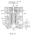
- Figs. 5-7 illustrate an actuator and valve assembly 90 which may be used in place of the actuator and valve assembly 29 in the fuel injector illustrated in Figs. 2A, 2B and 3.
- the assembly 90 includes an actuator 92 and a pilot valve 93.
- the actuator 92 may comprise a solenoid having a solenoid winding 94, an armature 96 and a plunger 98 coupled to the armature 96 and movable therewith.
- the plunger 98 extends into a valve element chamber 100 formed by a valve body member 102 of the pilot valve 93.
- a valve element in the form of a ball element 104 is disposed within the valve element chamber 100 and is movable between a first or upper position, seen in Figs.
- the valve body member 102 includes a passage 110 defining a low pressure port which is disposed in fluid communication with a drain passage 112 located in the actuator 92 and which is coupled to engine sump.
- a further passage 114 defines a high pressure port which interconnects the valve element chamber 100 with a chamber 116 within a movable spool 118.
- Each of one or more cross passages 120 defines an outlet port and interconnects the valve element chamber 100 with an end 122 of the spool 118.
- the spool 118 is disposed in sliding relationship within a bore 124 formed within a housing or body 126.
- the spool 118 is movable between a lower position, seen in Figs. 5 and 6, in which a second end 128 of the spool 118 is disposed in contact with a shouldered portion 132 of the body 126, and an upper position, seen in Fig. 7, wherein the upper end 122 of the spool 118 is in contact with the valve body member 102.
- the ball element 104 and the spool 118 are movable along parallel paths and, in the preferred embodiment, a longitudinal central axis 133 of the spool 118 (Fig. 6) is substantially coincident with a path of movement of the ball element 104.
- a spring 134 is placed in compression between the lower portion of 102 and a shouldered portion 136 of the spool 118 and biases the spool 118 to the lower position.
- the body 126 includes a high pressure inlet 140 which receives pressurized oil from the rail pressure control valve 24 of Fig. 1, a low pressure inlet 142 which may be coupled to any low pressure oil source, such as engine sump, and an outlet 144 which is coupled to the intensifier chamber 54. If desired, the actuator 92 may be secured to the body 126 by any suitable means, such as screws or any other fasteners.
- the ball element 104 When the actuator 92 is deenergized, the ball element 104 is in the position illustrated in Figs. 5 and 6 owing to the fluid pressure imbalance created by high pressure oil in the chamber 116 as introduced therein through the inlet 140 and a bore 146 in the spool 118 and the low fluid pressure present in the passage 110. Because the ball element 104 is in sealing engagement with the upper sealing surface 106 and is spaced from the lower sealing surface 108, the upper end 122 of the spool 118 is placed in fluid communication with the high pressure oil in the chamber 116. As a result, the fluid pressures on the ends 122, 128 of the spool 118 are equalized and the only force acting on the spool 118 is the bias exerted by the spring 134.
- the spool 118 is moved to the lower position shown in Figs. 5 and 6, thereby causing a sealing surface 150 of the spool 118 to be in sealing contact with a sealing surface 152 of the body 126. Further, a sealing surface 154 of the spool 118 is spaced from a sealing surface 156 of the body 126. Under these conditions, high pressure oil from the inlet 140 is blocked from the outlet 144 and the outlet 144 is placed in fluid communication with the low pressure inlet 142.
- the actuator force acts directly on a ball element, rather than on a spool or a poppet.
- a low force actuator can be used, for example one which develops a force as low as 50 newtons.
- Such an actuator could be relatively easily manufactured at low cost and can utilize low voltage driver signals from the engine controller 28.
- flow forces on the ball are significantly reduced as compared with other valves.
- the actuator force need not overcome a spring preload. Consequently, faster response can be achieved.
- valve performance can be optimized by varying different parameters, such as the biasing force exerted by the spring 134, the size, lift and ball seat flow areas, and the like.
- pilot valve other than the ball-type valve shown in the Figs. could alternatively be used.
- FIG. 8 illustrates a valve 160 according to the present invention wherein elements common to Fig. 8 and the remaining Figs. are assigned like reference numerals.
- the valve 160 includes the plunger 98 coupled to the actuator 92, the pilot valve 93 in the form of a ball valve and the spool 118.
- the spool 118 is disposed for sliding movement between first and second positions within a housing in the form of a sleeve 162.
- the sleeve 162 includes inner surfaces 164 which are identical to the inner surfaces of the body 126.
- the sleeve 162 further includes high and low pressure inlets 166, 168, which are identical to the high and low pressure inlets 140, 142, respectively, described above.
- An outlet 170 identical to the outlet 144 of Figs. 5-7, is in fluid communication with a fluid-driven actuator 172 which in turn contacts one or more intake or exhaust valves 174 of an engine.
- the actuator 92 when high pressure fluid is to be delivered to the actuator 172 to open the intake or exhaust valves 174, the actuator 92 is energized, thereby causing the pilot valve 93 to balance the fluid pressures across the spool 118 so that the spring 134 moves the spool 118 to a position which causes high pressure fluid at the high pressure inlet 166 to flow through the outlet 170 to the actuator 172.
- the actuator 92 When the intake or exhaust valves 174 are to be closed, the actuator 92 is deenergized, thereby causing the pilot valve 93 to develop a pressure differential across the spool 118 so that the spool is moved to a position which places the low pressure inlet 168 in fluid communication with the outlet 170.
- the low pressure fluid is delivered to the actuator 172 so that the intake or exhaust valves 174 may be closed by springs (not shown) acting thereagainst.
- the valve is easy to manufacture, assemble and install and is low in cost. Also, the flow lines for delivering fluid to the valve components are kept desirably short.
- the actuator may be of a different type, such as a solid-state motor comprising piezoelectric elements and an amplifier.
Claims (20)
- Distributeur (90, 160) comprenant :un boítier (126) comportant une entrée haute pression (140), une entrée basse pression (142), une sortie (144) et des première et seconde surfaces de joint (152, 156) ;une soupape pilote (93) disposée dans le boítier (126) et comprenant un élément de soupape (104) mobile entre des première et des seconde positions ; etun tiroir mobile (118) disposé dans le boítier (126) et comprenant des troisième et quatrième surfaces de joint (150, 154) engageables en contact glissant avec les première et seconde surfaces de joint (152, 156), respectivement, porté par le boítier (126) pour relier la sortie (144) à l'entrée basse pression (142) quand l'élément de soupape (104) est dans la première position et pour relier la sortie (144) à l'entrée haute pression (140) quand l'élément de soupape (104) est dans la seconde position, le tiroir (118) ayant des première et seconde extrémités (122, 128), la première extrémité (128) étant en communication de fluide avec l'entrée haute pression (140) quelle que soit la position de la soupape pilote.
- Distributeur (90, 160) selon la revendication 1, comprenant en outre un actionneur (92) actionnable pour déplacer l'élément de soupape (104) entre les première et seconde positions.
- Distributeur (90, 160) selon la revendication 2, dans lequel l'actionneur est fixé au boítier (126).
- Distributeur selon la revendication 1, comprenant en outre un ressort (134) qui sollicite le tiroir (118) vers une position particulière.
- Distributeur (90, 160) selon la revendication 1, dans lequel l'élément de soupape (104) comprend un élément de bille (104) mobile entre des premier et second sièges (106, 108).
- Distributeur (90, 160) selon la revendication 1, dans lequel l'actionneur (92) comprend un électro-aimant (94).
- Distributeur (90, 160) selon la revendication 1, adapté à actionner un injecteur de carburant, comprenant en outre :un actionneur (92) ;un corps (126, 162) comprenant ledit boítier (126) ;la soupape pilote (93) étant disposée dans le corps (126, 162) et comprenant un accès haute pression (114), un accès basse pression (110), un accès de sortie (120) et un élément de bille (104) déplaçable par l'actionneur (92) entre une première position dans laquelle l'accès haute pression (114) est en communication de fluide avec l'accès de sortie (120) et une seconde position dans laquelle l'accès basse pression (110) est en communication de fluide avec l'accès de sortie (120) ; etle tiroir mobile (118) étant disposé dans le corps (126, 162) et comportant des troisième et quatrième surfaces de joint (150, 154) pour entrer en contact avec les première et seconde surfaces de joint (152, 156), respectivement, du corps (126, 162), une première extrémité (128) en communication de fluide avec l'entrée haute pression (140, 166), et une seconde extrémité (122) en communication de fluide avec l'accès de sortie (120) de la soupape pilote (93).
- Distributeur (90, 160) selon la revendication 7, dans lequel l'actionneur (92) est fixé au corps (126, 162).
- Distributeur (90, 160) selon la revendication 1 ou 7, dans lequel l'élément de bille (104) et le tiroir (118) sont mobiles selon des trajets parallèles.
- Distributeur (90, 160) selon la revendication 1 ou 7, dans lequel le tiroir (118) comprend un axe central longitudinal (133) qui coïncide sensiblement avec un trajet de déplacement d'un point central de l'élément de bille (104) tandis que l'élément de bille (104) se déplace entre les première et seconde positions.
- Distributeur (90, 160) selon la revendication 1 ou 7, dans lequel la première surface de joint (152) est en communication de fluide avec l'entrée haute pression (140, 166) et la seconde surface de joint (156) est en communication de fluide avec l'entrée basse pression (142, 168).
- Distributeur (90, 160) selon la revendication 11, comprenant en outre un ressort (134) qui sollicite le tiroir (118) vers une position particulière à laquelle l'entrée basse pression (142, 168) est placée en communication de fluide avec la sortie (144, 170) du corps (126, 162).
- Distributeur (90, 160) selon la revendication 1 ou 12, en combinaison avec une source de fluide haute pression couplée à l'entrée haute pression (140, 166) et une source de fluide basse pression couplée à l'entrée basse pression (142, 168).
- Distributeur (90, 160) selon la revendication 13, dans lequel la soupape pilote (93) comprend un accès basse pression (110), un accès haute pression (114) et un accès de sortie (120) couplé à l'accès haute pression (114) ou à l'accès basse pression (110) quand l'élément de soupape (104) est dans la première ou la seconde position respectivement, et comprenant en outre un premier passage (116) entre l'entrée haute pression (140, 166) et l'accès haute pression (114) de la soupape pilote (93) et un second passage (112) entre l'accès basse pression (110) de la soupape pilote (93) et une sortie d'évacuation, et dans lequel une seconde extrémité (22) du tiroir (118) est en communication de fluide avec l'accès de sortie (120) de la soupape pilote (93).
- Distributeur (90, 160) selon la revendication 7, dans lequel la soupape pilote (93) est disposée dans le corps (126, 162) et comprend un accès haute pression (114) en communication de fluide avec la source de fluide haute pression, un accès basse pression (110) en communication de fluide avec une évacuation (112), un accès de sortie (120) et un élément de bille (104) mobile sous l'effet de l'actionneur (92) entre une première position d'élément de bille dans laquelle l'accès haute pression (114) est en communication de fluide avec l'accès de sortie (120) et une seconde position d'élément de bille dans laquelle l'accès basse pression (110) est en communication de fluide avec l'accès de sortie (120) ;le tiroir (118) étant mobile entre une première position de tiroir dans laquelle la troisième surface de joint (150) est en contact avec la première surface de joint (152) du corps (126) et une seconde position de tiroir dans laquelle la quatrième surface de joint (154) est en contact avec la seconde surface de joint (156) du corps (126) ; etle distributeur comprenant des moyens (134) pour solliciter le tiroir (118) vers la première position de tiroir.
- Distributeur d'actionnement d'injecteur de carburant (90, 160) selon la revendication 15, dans lequel l'actionneur (92) comprend un électroaimant (94) comportant un plongeur (98) en contact avec l'élément de bille (104).
- Distributeur d'actionnement d'injecteur de carburant (90, 160) selon la revendication 16, dans lequel l'élément de bille (104) se déplace selon un trajet coaxial avec le trajet de déplacement du tiroir (118).
- Distributeur (90, 160) selon la revendication 15, dans lequel le tiroir (118) est déplacé par un déséquilibre de pression de fluide de la première position de tiroir à la seconde position de tiroir.
- Distributeur (90, 160) selon la revendication 7 ou 15, en combinaison avec un injecteur de carburant couplé à la sortie (144, 170) du corps (126, 162).
- Distributeur (90, 160) selon la revendication 19, dans lequel l'injecteur de carburant est du type à actionnement hydraulique et à commande électronique.
Applications Claiming Priority (3)
| Application Number | Priority Date | Filing Date | Title |
|---|---|---|---|
| US452284 | 1989-12-15 | ||
| US08/452,284 US5720318A (en) | 1995-05-26 | 1995-05-26 | Solenoid actuated miniservo spool valve |
| PCT/US1996/005872 WO1996037700A1 (fr) | 1995-05-26 | 1996-04-25 | Distributeur a tiroir cylindrique de mini-servomecanisme actionne par electro-aimant |
Publications (2)
| Publication Number | Publication Date |
|---|---|
| EP0774067A1 EP0774067A1 (fr) | 1997-05-21 |
| EP0774067B1 true EP0774067B1 (fr) | 2001-06-06 |
Family
ID=23795874
Family Applications (1)
| Application Number | Title | Priority Date | Filing Date |
|---|---|---|---|
| EP19960913222 Expired - Lifetime EP0774067B1 (fr) | 1995-05-26 | 1996-04-25 | Distributeur a tiroir cylindrique de mini-servomecanisme actionne par electro-aimant |
Country Status (5)
| Country | Link |
|---|---|
| US (1) | US5720318A (fr) |
| EP (1) | EP0774067B1 (fr) |
| JP (1) | JPH10503570A (fr) |
| DE (1) | DE69613192T2 (fr) |
| WO (1) | WO1996037700A1 (fr) |
Families Citing this family (26)
| Publication number | Priority date | Publication date | Assignee | Title |
|---|---|---|---|---|
| US6161770A (en) | 1994-06-06 | 2000-12-19 | Sturman; Oded E. | Hydraulically driven springless fuel injector |
| US6257499B1 (en) | 1994-06-06 | 2001-07-10 | Oded E. Sturman | High speed fuel injector |
| US5884848A (en) * | 1997-05-09 | 1999-03-23 | Cummins Engine Company, Inc. | Fuel injector with piezoelectric and hydraulically actuated needle valve |
| US5975139A (en) * | 1998-01-09 | 1999-11-02 | Caterpillar Inc. | Servo control valve for a hydraulically-actuated device |
| US6085991A (en) | 1998-05-14 | 2000-07-11 | Sturman; Oded E. | Intensified fuel injector having a lateral drain passage |
| US6286483B1 (en) | 1999-04-19 | 2001-09-11 | International Truck And Engine Corporation | Fuel injector with actuation pressure delay device |
| BR0010759A (pt) | 1999-05-18 | 2002-02-19 | Int Engine Intellectual Prop | Dispositivo de controle hidráulico em dois estágios, com dupla atuação |
| US6142394A (en) * | 1999-06-30 | 2000-11-07 | Caterpillar Inc. | Valve seat for a ball and pin valve member in a hydraulically actuated fuel injector |
| IT1308779B1 (it) * | 1999-07-02 | 2002-01-10 | Elasis Sistema Ricerca Fiat | Dispositivo di regolazione della pressione di mandata di una pompa,adesempio per l'alimentazione di combustibile ad un motore a combustione |
| DE19938865A1 (de) * | 1999-08-17 | 2001-02-15 | Siemens Ag | Magnetventil für Injektoren |
| US6298826B1 (en) | 1999-12-17 | 2001-10-09 | Caterpillar Inc. | Control valve with internal flow path and fuel injector using same |
| US6283441B1 (en) | 2000-02-10 | 2001-09-04 | Caterpillar Inc. | Pilot actuator and spool valve assembly |
| DE10006786A1 (de) * | 2000-02-18 | 2001-08-30 | Bosch Gmbh Robert | Einspritzeinrichtung und Verfahren zum Einspritzen von Fluid |
| US6354270B1 (en) * | 2000-06-29 | 2002-03-12 | Caterpillar Inc. | Hydraulically actuated fuel injector including a pilot operated spool valve assembly and hydraulic system using same |
| DE10031580A1 (de) * | 2000-06-29 | 2002-01-17 | Bosch Gmbh Robert | Druckgesteuertes Steuerteil für Common-Rail-Injektoren |
| US6454189B1 (en) * | 2000-07-03 | 2002-09-24 | Caterpillar Inc. | Reverse acting nozzle valve and fuel injector using same |
| US6401693B1 (en) | 2000-09-01 | 2002-06-11 | Schrader-Bridgeport International, Inc. | Pressure spike attenuator for automotive fuel injection system |
| US6601566B2 (en) | 2001-07-11 | 2003-08-05 | Caterpillar Inc | Fuel injector with directly controlled dual concentric check and engine using same |
| JP3888519B2 (ja) * | 2001-09-12 | 2007-03-07 | 株式会社デンソー | 排気浄化装置 |
| US6978943B2 (en) * | 2002-01-30 | 2005-12-27 | International Engine Intellectual Property Company, Llc | Governor plate apparatus |
| US20070266994A1 (en) * | 2004-01-25 | 2007-11-22 | Mazrek Ltd. | Hydraulically Driven Pump-Injector for Internal Compustion Engines with Hydromechanical Return Device of the Power Piston |
| WO2008076239A2 (fr) * | 2006-12-15 | 2008-06-26 | Wabash Technologies, Inc. | Injecteur de carburant muni d'un élément de soupape équilibré |
| DE102008002527A1 (de) * | 2008-06-19 | 2009-12-24 | Robert Bosch Gmbh | Kraftstoff-Injektor |
| WO2013067215A1 (fr) | 2011-11-01 | 2013-05-10 | Cummins Inc. | Injecteur de combustible doté d'une cartouche de soupape de commande d'injection |
| US9212639B2 (en) * | 2012-11-02 | 2015-12-15 | Caterpillar Inc. | Debris robust fuel injector with co-axial control valve members and fuel system using same |
| CN103850999B (zh) * | 2012-11-29 | 2017-03-29 | 中国船舶重工集团公司第七一一研究所 | 用于高压共轨系统的油泵进油量调节控制阀 |
Family Cites Families (99)
| Publication number | Priority date | Publication date | Assignee | Title |
|---|---|---|---|---|
| US2144862A (en) * | 1937-04-03 | 1939-01-24 | Gen Motors Corp | Fuel pump injector |
| US2535937A (en) * | 1939-07-19 | 1950-12-26 | Bozec Leon Le | Fuel injecting means for motors |
| US2421329A (en) * | 1941-07-08 | 1947-05-27 | Ex Cell O Corp | Fuel injection nozzle |
| US2512557A (en) * | 1944-02-24 | 1950-06-20 | Ex Cell O Corp | Fuel injection nozzle |
| US2434586A (en) * | 1945-02-06 | 1948-01-13 | Harold B Reynolds | Electromagnetic pulsator valve |
| US2621011A (en) * | 1946-11-20 | 1952-12-09 | Maytag Co | High-pressure valve seal |
| US2597952A (en) * | 1947-09-02 | 1952-05-27 | Packard Motor Car Co | Valve construction |
| US2672827A (en) * | 1949-11-22 | 1954-03-23 | Sid W Richardson Inc | Gas lift valve mechanism |
| US2552445A (en) * | 1950-02-08 | 1951-05-08 | Clarissa E Caird | Fire hose nozzle |
| US2727498A (en) * | 1953-02-25 | 1955-12-20 | Cummins Engine Co Inc | Fuel supply apparatus for an internal combustion engine |
| US2749181A (en) * | 1954-04-01 | 1956-06-05 | Caterpillar Tractor Co | Fuel injection nozzle and valve assembly |
| US2913005A (en) * | 1956-07-23 | 1959-11-17 | Hughes Tool Co | Pilot-actuated control valve |
| US2916048A (en) * | 1957-01-25 | 1959-12-08 | Bendix Aviat Corp | Magnetically actuated valve |
| US3071714A (en) * | 1959-01-30 | 1963-01-01 | Sperry Gyroscope Co Ltd | Electromagnetic actuators |
| US3035780A (en) * | 1960-05-20 | 1962-05-22 | Renault | Fuel injection nozzles for internal combustion engines |
| US3057560A (en) * | 1960-07-19 | 1962-10-09 | John F Campbell | Nozzle construction |
| FR1312045A (fr) * | 1961-11-04 | 1962-12-14 | Perfectionnement aux injecteurs de combustible pour moteurs thermiques | |
| US3410519A (en) * | 1966-01-24 | 1968-11-12 | Caterpillar Tractor Co | Relief valve |
| US3570807A (en) * | 1969-01-14 | 1971-03-16 | Bell Aerospace Corp | Electromechanical control valve |
| US3570806A (en) * | 1969-01-14 | 1971-03-16 | Bell Aerospace Corp | Balanced electromechanical control valve |
| US3570833A (en) * | 1969-01-15 | 1971-03-16 | Bell Aerospace Corp | Step control |
| US3532121A (en) * | 1969-01-15 | 1970-10-06 | Bell Aerospace Corp | Latching valve |
| US3585547A (en) * | 1969-07-15 | 1971-06-15 | Bell Aerospace Corp | Electromagnetic force motors having extended linearity |
| US3604959A (en) * | 1969-12-15 | 1971-09-14 | Fema Corp | Linear motion electromechanical device utilizing nonlinear elements |
| US3743898A (en) * | 1970-03-31 | 1973-07-03 | Oded Eddie Sturman | Latching actuators |
| US3675853A (en) * | 1971-02-25 | 1972-07-11 | Parker Hannifin Corp | Fuel nozzle with modulating primary nozzle |
| GB1338143A (en) * | 1971-03-27 | 1973-11-21 | English Calico | Liquid control valves |
| DE2126653A1 (de) * | 1971-05-28 | 1972-12-07 | Robert Bosch Gmbh, 7000 Stuttgart | Kraftstoffeinspritzeinrichtung für Brennkraftmaschinen |
| US3683239A (en) * | 1971-06-17 | 1972-08-08 | Oded E Sturman | Self-latching solenoid actuator |
| US3989066A (en) * | 1971-12-30 | 1976-11-02 | Clifton J. Burwell by said Oded E. Sturman and said Benjamin Grill | Fluid control system |
| US3821967A (en) * | 1971-12-30 | 1974-07-02 | O Sturman | Fluid control system |
| US3814376A (en) * | 1972-08-09 | 1974-06-04 | Parker Hannifin Corp | Solenoid operated valve with magnetic latch |
| JPS49108427A (fr) * | 1973-02-19 | 1974-10-15 | ||
| US3858135A (en) * | 1973-08-14 | 1974-12-31 | S Gray | Push-pull linear motor |
| JPS5175222A (fr) * | 1974-12-25 | 1976-06-29 | Konan Electric Co | |
| US3952711A (en) * | 1975-03-04 | 1976-04-27 | Ambac Industries, Inc. | Diesel injection nozzle with independent opening and closing control |
| US4087736A (en) * | 1975-07-22 | 1978-05-02 | Nippondenso Co., Ltd. | Current generating system |
| JPS52100418U (fr) * | 1976-01-28 | 1977-07-29 | ||
| US4108419A (en) * | 1976-03-01 | 1978-08-22 | Clifton J. Burwell | Pilot operated valve |
| US4114647A (en) * | 1976-03-01 | 1978-09-19 | Clifton J. Burwell | Fluid control system and controller and moisture sensor therefor |
| FR2372348A1 (fr) * | 1976-10-26 | 1978-06-23 | Roulements Soc Nouvelle | Bague composite pour roulement et son procede de fabrication |
| US4087773A (en) * | 1976-11-15 | 1978-05-02 | Detroit Coil Company | Encapsulated solenoid |
| US4152676A (en) * | 1977-01-24 | 1979-05-01 | Massachusetts Institute Of Technology | Electromagnetic signal processor forming localized regions of magnetic wave energy in gyro-magnetic material |
| JPS5836176B2 (ja) * | 1977-02-21 | 1983-08-08 | 株式会社クボタ | 内燃機関の停止時における徐冷運転装置 |
| DE2750928A1 (de) * | 1977-11-15 | 1979-05-17 | Maschf Augsburg Nuernberg Ag | Kraftstoff-einspritzduese fuer brennkraftmaschinen |
| US4275693A (en) * | 1977-12-21 | 1981-06-30 | Leckie William H | Fuel injection timing and control apparatus |
| DE2758057A1 (de) * | 1977-12-24 | 1979-06-28 | Daimler Benz Ag | Doppelnadel-einspritzventil |
| US4231525A (en) * | 1979-05-10 | 1980-11-04 | General Motors Corporation | Electromagnetic fuel injector with selectively hardened armature |
| DE2930716A1 (de) * | 1979-07-28 | 1981-02-19 | Daimler Benz Ag | Drosselzapfenduese |
| US4248270A (en) * | 1980-01-11 | 1981-02-03 | The Singer Company | Reduced noise water valve provided with flow control |
| SU981664A1 (ru) | 1980-02-11 | 1982-12-15 | Центральный Научно-Исследовательский И Конструкторский Институт Топливной Аппаратуры Автотракторных И Стационарных Двигателей | Корпус распылител форсунки двигател внутреннего сгорани |
| US4308891A (en) * | 1980-03-31 | 1982-01-05 | Double A Products Co. | Terminal blocks and indicator for solenoid valves |
| US4354662A (en) * | 1980-04-30 | 1982-10-19 | Sanders Associates, Inc. | Force motor |
| GB2076125B (en) * | 1980-05-17 | 1984-03-07 | Expert Ind Controls Ltd | Electro-hydraulic control valve |
| US4409638A (en) * | 1981-10-14 | 1983-10-11 | Sturman Oded E | Integrated latching actuators |
| US4875499A (en) * | 1981-10-16 | 1989-10-24 | Borg-Warner Corporation | Proportional solenoid valve |
| US4541454A (en) * | 1981-12-07 | 1985-09-17 | Sturman Oded E | Pressure regulators |
| US4392612A (en) * | 1982-02-19 | 1983-07-12 | General Motors Corporation | Electromagnetic unit fuel injector |
| JPS58183857A (ja) * | 1982-04-22 | 1983-10-27 | Nissan Motor Co Ltd | 燃料噴射装置 |
| US4516600A (en) * | 1982-05-14 | 1985-05-14 | Sturman Oded E | Pressure regulating valves |
| US4526519A (en) * | 1982-08-03 | 1985-07-02 | Lucas Industries | Reciprocable plunger fuel injection pump |
| US4501290A (en) * | 1982-09-30 | 1985-02-26 | Sturman Oded E | Pressure regulating mechanically and electrically operable shut off valves |
| DE3300624C2 (de) * | 1983-01-11 | 1984-11-15 | Danfoss A/S, Nordborg | Ventil mit Voreinstellung der Durchflußmenge |
| US4544096A (en) * | 1983-07-28 | 1985-10-01 | Energy Conservation Innovations, Inc. | Electronically controlled fuel injection system for diesel engine |
| US4482094A (en) * | 1983-09-06 | 1984-11-13 | General Motors Corporation | Electromagnetic unit fuel injector |
| US5049971A (en) * | 1983-10-21 | 1991-09-17 | Hughes Aircraft Company | Monolithic high-frequency-signal switch and power limiter device |
| DE3429471A1 (de) * | 1984-08-10 | 1986-02-13 | L'Orange GmbH, 7000 Stuttgart | Kraftstoffeinspritzvorrichtung fuer eine brennkraftmaschine |
| EP0178427B1 (fr) * | 1984-09-14 | 1990-12-27 | Robert Bosch Gmbh | Pompe d'injection de carburant commandée par électricité pour moteurs à combustion interne |
| JPS61118556A (ja) * | 1984-11-14 | 1986-06-05 | Toyota Central Res & Dev Lab Inc | 間欠式渦巻噴射弁 |
| GB8430259D0 (en) * | 1984-11-30 | 1985-01-09 | Lucas Ind Plc | Electromagnetically operable valve |
| US4610428A (en) * | 1985-03-11 | 1986-09-09 | Borg-Warner Automotive, Inc. | Hermetically sealed electromagnetic solenoid valve |
| US4558844A (en) * | 1985-04-11 | 1985-12-17 | Appliance Valves Corporation | Direct acting valve assembly |
| GB8527827D0 (en) * | 1985-11-12 | 1985-12-18 | Lucas Ind Plc | Control valve |
| JPH0450102Y2 (fr) * | 1986-02-25 | 1992-11-26 | ||
| ATE73207T1 (de) * | 1986-05-22 | 1992-03-15 | Osamu Matsumura | Einspritzvorrichtung fuer kraftstoff. |
| DE3629646A1 (de) * | 1986-08-30 | 1988-03-03 | Bosch Gmbh Robert | Elektromagnetisch betaetigbares kraftstoffeinspritzventil |
| US4811221A (en) * | 1986-10-28 | 1989-03-07 | Galcon | Simplified battery operated automatic and manually operable valve |
| US4893102A (en) * | 1987-02-19 | 1990-01-09 | Westinghouse Electric Corp. | Electromagnetic contactor with energy balanced closing system |
| US4794890A (en) * | 1987-03-03 | 1989-01-03 | Magnavox Government And Industrial Electronics Company | Electromagnetic valve actuator |
| US4812884A (en) * | 1987-06-26 | 1989-03-14 | Ledex Inc. | Three-dimensional double air gap high speed solenoid |
| US4846440A (en) * | 1987-09-30 | 1989-07-11 | Spectra Physics | Valve with metal diaphragm and flat surface valve body |
| FR2624208B1 (fr) * | 1987-12-04 | 1990-03-30 | Renault Vehicules Ind | Dispositif de guidage cylindrique a compensation de jeu de fonctionnement |
| JPH01224454A (ja) * | 1988-03-04 | 1989-09-07 | Yamaha Motor Co Ltd | エンジンの高圧燃料噴射装置 |
| US4893652A (en) * | 1988-04-29 | 1990-01-16 | Chrysler Motors Corporation | Direct-acting, non-close clearance solenoid-actuated valves |
| JPH0286953A (ja) * | 1988-09-21 | 1990-03-27 | Kanesaka Gijutsu Kenkyusho:Kk | 燃料噴射弁 |
| US5042445A (en) * | 1988-09-23 | 1991-08-27 | Cummins Engine Company, Inc. | Electronic controlled fuel supply system for high pressure injector |
| JPH0635812B2 (ja) * | 1988-10-31 | 1994-05-11 | いすゞ自動車株式会社 | 電磁力駆動バルブ制御装置 |
| DE3920976A1 (de) * | 1989-06-27 | 1991-01-03 | Fev Motorentech Gmbh & Co Kg | Elektromagnetisch arbeitende stelleinrichtung |
| DE3921151A1 (de) * | 1989-06-28 | 1991-01-10 | Bosch Gmbh Robert | Magnetsystem |
| GB8924118D0 (en) * | 1989-10-26 | 1989-12-13 | Lucas Ind Plc | Fuel injection nozzles for internal combustion engines |
| US5004577A (en) * | 1989-12-06 | 1991-04-02 | General Motors Corporation | Frame and magnet assembly for a dynamoelectric machine |
| US5110087A (en) * | 1990-06-25 | 1992-05-05 | Borg-Warner Automotive Electronic & Mechanical Systems Corporation | Variable force solenoid hydraulic control valve |
| US5051631A (en) * | 1990-07-16 | 1991-09-24 | Spx Corporation | Electromagnetic solenoid valve with variable force motor |
| DE4024054A1 (de) * | 1990-07-28 | 1992-01-30 | Bosch Gmbh Robert | Magnetsystem |
| DE69121904D1 (de) * | 1991-10-11 | 1996-10-10 | Caterpillar Inc | Gedämpfte betätigungs- und ventilanordnung für eine elektronisch-gesteuerte einspritzeinheit |
| US5191867A (en) * | 1991-10-11 | 1993-03-09 | Caterpillar Inc. | Hydraulically-actuated electronically-controlled unit injector fuel system having variable control of actuating fluid pressure |
| US5121730A (en) * | 1991-10-11 | 1992-06-16 | Caterpillar Inc. | Methods of conditioning fluid in an electronically-controlled unit injector for starting |
| FR2683337B1 (fr) * | 1991-10-31 | 1994-01-07 | Bendix Europe Services Technique | Dispositif de regulation de pression pour circuit hydraulique. |
| US5339777A (en) * | 1993-08-16 | 1994-08-23 | Caterpillar Inc. | Electrohydraulic device for actuating a control element |
-
1995
- 1995-05-26 US US08/452,284 patent/US5720318A/en not_active Expired - Fee Related
-
1996
- 1996-04-25 JP JP53566596A patent/JPH10503570A/ja not_active Withdrawn
- 1996-04-25 WO PCT/US1996/005872 patent/WO1996037700A1/fr active IP Right Grant
- 1996-04-25 DE DE1996613192 patent/DE69613192T2/de not_active Expired - Fee Related
- 1996-04-25 EP EP19960913222 patent/EP0774067B1/fr not_active Expired - Lifetime
Also Published As
| Publication number | Publication date |
|---|---|
| US5720318A (en) | 1998-02-24 |
| DE69613192T2 (de) | 2002-01-31 |
| JPH10503570A (ja) | 1998-03-31 |
| WO1996037700A1 (fr) | 1996-11-28 |
| DE69613192D1 (de) | 2001-07-12 |
| EP0774067A1 (fr) | 1997-05-21 |
Similar Documents
| Publication | Publication Date | Title |
|---|---|---|
| EP0774067B1 (fr) | Distributeur a tiroir cylindrique de mini-servomecanisme actionne par electro-aimant | |
| US5651345A (en) | Direct operated check HEUI injector | |
| JP3468813B2 (ja) | 内燃機関のための燃料噴射装置 | |
| KR100482901B1 (ko) | 내연기관에사용되는연료분사장치 | |
| EP0774066B1 (fr) | Soupape a tiroir cylindrique a commande directe pour injecteur de carburant | |
| US5423484A (en) | Injection rate shaping control ported barrel for a fuel injection system | |
| US7267109B2 (en) | Fuel injection device for an internal combustion engine | |
| JPH06299928A (ja) | 内燃機関の燃料噴射装置 | |
| JP2001505975A (ja) | 燃料噴射弁 | |
| JPH07332193A (ja) | 内燃機関用の燃料噴射弁 | |
| US4941612A (en) | Unit fuel injector | |
| US5487508A (en) | Injection rate shaping control ported check stop for a fuel injection nozzle | |
| US6026785A (en) | Hydraulically-actuated fuel injector with hydraulically assisted closure of needle valve | |
| EP1163440A1 (fr) | Injecteur de carburant | |
| US5832954A (en) | Check valve assembly for inhibiting Helmholtz resonance | |
| US5826561A (en) | Method and apparatus for injecting fuel using control fluid to control the injection's pressure and time | |
| US5934559A (en) | Electronic fuel injector with internal single-pole solenoid and center flow post | |
| US6390070B2 (en) | Pressure-intensifying hydraulically-actuated electronically-controlled fuel injection system with individual mechanical unit pumps | |
| US6129072A (en) | Hydraulically actuated device having a ball valve member | |
| US6354270B1 (en) | Hydraulically actuated fuel injector including a pilot operated spool valve assembly and hydraulic system using same | |
| US5282574A (en) | Hydraulic flow shutoff device for a unit fuel pump/injector | |
| WO2005066485A1 (fr) | Injecteur de carburant a actionneur piezoelectrique et procede d'utilisation correspondant | |
| JPH0666219A (ja) | ディーゼル機関用燃料噴射装置 | |
| US6298826B1 (en) | Control valve with internal flow path and fuel injector using same | |
| US20060054138A1 (en) | Fuel injection system with integrated pressure booster |
Legal Events
| Date | Code | Title | Description |
|---|---|---|---|
| PUAI | Public reference made under article 153(3) epc to a published international application that has entered the european phase |
Free format text: ORIGINAL CODE: 0009012 |
|
| AK | Designated contracting states |
Kind code of ref document: A1 Designated state(s): DE GB SE |
|
| 17P | Request for examination filed |
Effective date: 19970522 |
|
| 17Q | First examination report despatched |
Effective date: 19990125 |
|
| GRAG | Despatch of communication of intention to grant |
Free format text: ORIGINAL CODE: EPIDOS AGRA |
|
| GRAG | Despatch of communication of intention to grant |
Free format text: ORIGINAL CODE: EPIDOS AGRA |
|
| GRAH | Despatch of communication of intention to grant a patent |
Free format text: ORIGINAL CODE: EPIDOS IGRA |
|
| GRAH | Despatch of communication of intention to grant a patent |
Free format text: ORIGINAL CODE: EPIDOS IGRA |
|
| GRAA | (expected) grant |
Free format text: ORIGINAL CODE: 0009210 |
|
| AK | Designated contracting states |
Kind code of ref document: B1 Designated state(s): DE GB SE |
|
| REF | Corresponds to: |
Ref document number: 69613192 Country of ref document: DE Date of ref document: 20010712 |
|
| PG25 | Lapsed in a contracting state [announced via postgrant information from national office to epo] |
Ref country code: SE Free format text: LAPSE BECAUSE OF FAILURE TO SUBMIT A TRANSLATION OF THE DESCRIPTION OR TO PAY THE FEE WITHIN THE PRESCRIBED TIME-LIMIT Effective date: 20010906 |
|
| REG | Reference to a national code |
Ref country code: GB Ref legal event code: IF02 |
|
| PLBE | No opposition filed within time limit |
Free format text: ORIGINAL CODE: 0009261 |
|
| STAA | Information on the status of an ep patent application or granted ep patent |
Free format text: STATUS: NO OPPOSITION FILED WITHIN TIME LIMIT |
|
| 26N | No opposition filed | ||
| PGFP | Annual fee paid to national office [announced via postgrant information from national office to epo] |
Ref country code: GB Payment date: 20050314 Year of fee payment: 10 |
|
| PGFP | Annual fee paid to national office [announced via postgrant information from national office to epo] |
Ref country code: DE Payment date: 20050429 Year of fee payment: 10 |
|
| PG25 | Lapsed in a contracting state [announced via postgrant information from national office to epo] |
Ref country code: GB Free format text: LAPSE BECAUSE OF NON-PAYMENT OF DUE FEES Effective date: 20060425 |
|
| PG25 | Lapsed in a contracting state [announced via postgrant information from national office to epo] |
Ref country code: DE Free format text: LAPSE BECAUSE OF NON-PAYMENT OF DUE FEES Effective date: 20061101 |
|
| GBPC | Gb: european patent ceased through non-payment of renewal fee |
Effective date: 20060425 |