EP0773879B1 - Rigg, insbesondere für fahrrad - Google Patents
Rigg, insbesondere für fahrrad Download PDFInfo
- Publication number
- EP0773879B1 EP0773879B1 EP95926994A EP95926994A EP0773879B1 EP 0773879 B1 EP0773879 B1 EP 0773879B1 EP 95926994 A EP95926994 A EP 95926994A EP 95926994 A EP95926994 A EP 95926994A EP 0773879 B1 EP0773879 B1 EP 0773879B1
- Authority
- EP
- European Patent Office
- Prior art keywords
- rigging
- sail
- vehicle
- frame
- tubes
- Prior art date
- Legal status (The legal status is an assumption and is not a legal conclusion. Google has not performed a legal analysis and makes no representation as to the accuracy of the status listed.)
- Expired - Lifetime
Links
Images


Classifications
-
- B—PERFORMING OPERATIONS; TRANSPORTING
- B62—LAND VEHICLES FOR TRAVELLING OTHERWISE THAN ON RAILS
- B62B—HAND-PROPELLED VEHICLES, e.g. HAND CARTS OR PERAMBULATORS; SLEDGES
- B62B15/00—Other sledges; Ice boats or sailing sledges
- B62B15/001—Other sledges; Ice boats or sailing sledges propelled by sails
- B62B15/004—Other sledges; Ice boats or sailing sledges propelled by sails having wheels
- B62B15/005—Other sledges; Ice boats or sailing sledges propelled by sails having wheels the arrangement is similar to a bicycle
-
- B—PERFORMING OPERATIONS; TRANSPORTING
- B62—LAND VEHICLES FOR TRAVELLING OTHERWISE THAN ON RAILS
- B62K—CYCLES; CYCLE FRAMES; CYCLE STEERING DEVICES; RIDER-OPERATED TERMINAL CONTROLS SPECIALLY ADAPTED FOR CYCLES; CYCLE AXLE SUSPENSIONS; CYCLE SIDECARS, FORECARS, OR THE LIKE
- B62K17/00—Cycles not otherwise provided for
-
- B—PERFORMING OPERATIONS; TRANSPORTING
- B62—LAND VEHICLES FOR TRAVELLING OTHERWISE THAN ON RAILS
- B62M—RIDER PROPULSION OF WHEELED VEHICLES OR SLEDGES; POWERED PROPULSION OF SLEDGES OR SINGLE-TRACK CYCLES; TRANSMISSIONS SPECIALLY ADAPTED FOR SUCH VEHICLES
- B62M23/00—Transmissions characterised by use of other elements; Other transmissions
- B62M23/02—Transmissions characterised by use of other elements; Other transmissions characterised by the use of two or more dissimilar sources of power, e.g. transmissions for hybrid motorcycles
-
- B—PERFORMING OPERATIONS; TRANSPORTING
- B62—LAND VEHICLES FOR TRAVELLING OTHERWISE THAN ON RAILS
- B62M—RIDER PROPULSION OF WHEELED VEHICLES OR SLEDGES; POWERED PROPULSION OF SLEDGES OR SINGLE-TRACK CYCLES; TRANSMISSIONS SPECIALLY ADAPTED FOR SUCH VEHICLES
- B62M6/00—Rider propulsion of wheeled vehicles with additional source of power, e.g. combustion engine or electric motor
Definitions
- the subject of the present invention is a symmetrical rigging with qualities improved aerodynamics and simplified handling allowing its user to maintain great freedom of movement, especially on a bicycle while maintaining the intrinsic qualities of pedaling, evolution, clutter and allowing hands to be kept free for hold the handlebars regardless of the conditions of use or transport of the rigging out of use.
- the present invention aims to remedy these drawbacks by the synthesis of various existing achievements, in particular improvements made to the rigging which is the subject of patent EP-A-0 151 591, of FR-A-1 156 952 and German patent DE-A 3208340.
- the rigging according to the invention is defined by claim 1.
- FR-A-1 156 952 describes an elliptical or circular sail oriented relative to the boat by connecting rods, wires or cables.
- DE-A 3208340 describes a velic frame composed of horizontal and vertical elements.
- EP-A-0 151 591 describes a removable elliptical frame made up of two flexible uprights joined by their ends themselves connected by a tensioner making it possible to modify the bending of the uprights and consequently the sail hollow, this tensioner passing to the outside of a horizontal spar fixed to the uprights.
- the rigging is made asymmetrical by lateral deformation of the frame consisting of two vertical uprights and two horizontal bars joining the ends of the uprights, this deformation being obtained by transverse stressing of the tensioner uniting the bars vertical which itself is integral with the horizontal spar uniting the uprights by means of a pole pivoting from the middle of the spar.
- the rigging is associated with a bicycle thanks to two bent arms, fixed by a joint to the sides of the rigging, which are engaged in two parallel tubes located on the side and on the other side of the bicycle frame, swiveling around a horizontal solid axis of the frame.
- the two tubes also support the elements of a gallows surrounding the steering column and having at its end a command to control the position and profile of the rig.
- This order can be a rope passing through a pulley fixed to the gallows and connecting a part of the rigging, in particular the rigging tensioner.
- the sail is provided on its perimeter of a lace whose tightening makes it possible to wrap the uprights and bars rigging in the fold of the sail so that the sail surface presents an aerodynamic upper surface in relation to the uprights.
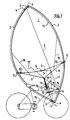
- FIGS. 1 and 2 the sail 1 is stretched over the uprights 2 and the bars 3 in wrapping them in a fold surrounded by an Ibis lace (Fig 2) whose tightening allows to control the wrapping.
- Bars 3 are joined at the ends high and low uprights 2 by joints 4 allowing the deformation of the quadrilateral thus defined.
- a middle tensioner 8 adjustable in length, join the two bars 3 passing at the end of a pole 7 mounted on the spar 5 by a hinge 6.
- On the spar 5 are reported two arms 9 by two joints 10. The arms are bent and their ends are journalled in two tubes 11.
- tubes 11 comprising dishes are located on either side of the frame 19 by two axes 12 and 13.
- the axis 12 is fixedly mounted below the frame 19 in a caliper 14 which surrounds the steering column of the bicycle. This axis 12 allows the tilting of the tubes 11 from front to back.
- Axis 13 is located above the frame 19.
- Solid with tubes 11, four rods 15 assembled at one of their ends constitute a non-deformable stem tilting from top to bottom.
- a pulley 16 allows the passage of a control 17 fixed to the rigging tensioner 8.
- Frame 19 is protected from friction of tubes 11 by plastic sheaths.
- Figure 3 illustrates the asymmetric deformation of the sail by the thrust of the spar 5 caused by the pole 7 when the tensioner 8 is oriented on the side of the leading edge of the sail 1. Indeed, on this edge, the amount 2 tends to fall off, causing the bars 3 to move towards the extension of the upright 2 located at the trailing edge. So the hollow of the veil moves forward, increasing the efficiency of the sail.
- guards 18 shown in Figure 1 which join the amounts of the rigging to the arms 9 and prohibit at the bottom of the rigging to come into contact with the bicycle in case, for some reason arbitrary, the command 17 is not held by the cyclist.
- Figure 6 shows that the transport of the folded rigging and wrapped, carried on the arms 9 engaged rearward in the support 11 not bother the cyclist to move with the pedals.
- the support shown in FIG. 4 can remain permanently in place on the bicycle, which limits the set-up time rigging work.
- the present invention is not limited to bicycles but can be used on any land or water vehicle likely to be moved by the wind.
Landscapes
- Engineering & Computer Science (AREA)
- Mechanical Engineering (AREA)
- Chemical & Material Sciences (AREA)
- Combustion & Propulsion (AREA)
- Transportation (AREA)
- Steering Devices For Bicycles And Motorcycles (AREA)
- Jib Cranes (AREA)
- Motorcycle And Bicycle Frame (AREA)
Claims (9)
- Rigg, insbesondere für ein Fahrrad (19) oder ein anderes Fahrzeug, das ein Segel (1) und eine Montagehalterung (11) für das Segel an dem Fahrrad oder dem anderen Fahrzeug umfaßt, wobei das Segel (1) auf zwei flexible Holme (2) gespannt ist, auf denen ein Spannmittel (8) festgelegt ist,
dadurch gekennzeichnet, daß
das Segel (1) auf einen Rahmen gespannt ist, der die beiden flexiblen Holme (2) enthält, die an ihren Enden mit zwei Zwischengliedern (3) mittels Gelenkverbindungen (4) verbunden sind, wobei die Zwischenglieder (3) in einem Ruhezustand lotrecht zur Richtung des Spannmittels (8) orientiert sind, und wobei ein Einwirken auf das Spannmittel (8) die symmetrische Form des Rahmens (2, 3) in eine unsymmetrische Form überführt. - Rigg nach Anspruch 1, dadurch gekennzeichnet, daß es eine Latte (5) umfaßt, auf der ein Schwingbaum (7) an seinem einen Ende (6) mittels einer Gelenkverbindung montiert ist, wobei dessen zweites Ende gleitend an dem Spannmittel (8) festgelegt ist.
- Rigg nach Anspruch 1, dadurch gekennzeichnet, daß das Segel (1) auf die Holme (2) und die Zwischenglieder (3) gespannt ist, wobei es sie mittels einer einstellbaren umlaufenden Leine (lbis) umschließt.
- Rigg nach Anspruch 1, dadurch gekennzeichnet, daß die Latte (5) mit zwei Haltearmen (9) verbunden ist, die ein Haltemittel für das Halten des Segels in einer seitlichen Stellung bezüglich des durch den Wind angetriebenen Fahrzeuges (19) darstellen.
- Rigg nach den Ansprüchen 1 bis 4, dadurch gekennzeichnet, daß jeder Haltearm (9) eine Abwinklung aufweist, wobei das der Gelenkverbindung (10) entgegengesetzte Ende drehbar in einem der beiden parallelen Rohre des Trägermittels (11) festgelegt ist, die auf beiden Seiten des Rahmens des Fahrzeugs (19) angebracht sind, um das Halten oder das Neigen des Segelriggs in einer zur Fahrzeugachse des Fahrzeug (19) parallelen Ebene zu ermöglichen, wobei die Rohre (11) durch eine horizontale Achse (12) verbunden sind, die unterhalb des Rahmens des Fahrzeuges (19) liegt, wobei die Achse (12) mittels einer Halterung (14) gehalten wird, die an der Lenksäule des Fahrzeugs festgelegt ist.
- Rigg nach Anspruch 5, dadurch gekennzeichnet, daß die Rohre (11) durch eine zweite Achse (13) verbunden sind, die oberhalb des Rahmens (19) verläuft, um das Schwenken der Rohre (11) um die untere Achse (12) zu ermöglichen, wobei die Rohre (11) mit einem Ausleger (15) versehen sind, der nach vorne gerichtet ist.
- Rigg nach Anspruch 6, dadurch gekennzeichnet, daß die Halterung (11) einen Ausleger (15) umfaßt, der nach vorne zeigt und aus vier Stangen besteht, die auf beiden Seiten der Lenksäule verlaufen und an die Rohre der Halterung (11) mittels der Achsen (12, 13) festgelegt sind, wobei ein Seilblock (16) an das vordere Ende des Auslegers (15) montiert ist.
- Rigg nach Anspruch 7, dadurch gekennzeichnet, daß ein Zug-Steuermittel (17), das mit einem seiner Enden mit dem Benutzer verbunden ist, über den Seilblock (16) läuft, wobei das zweite Ende des Zug-Steuermittels (17) mit dem Spannmittel (8) verbunden ist.
- Rigg nach den Ansprüchen 1 und 5, dadurch gekennzeichnet, daß seine Neigung bezüglich des Rahmens (19) des Fahrrads durch ein Sicherheitssystem (18) begrenzt wird.
Applications Claiming Priority (3)
| Application Number | Priority Date | Filing Date | Title |
|---|---|---|---|
| FR9409514 | 1994-08-01 | ||
| FR9409514A FR2723065B3 (fr) | 1994-08-01 | 1994-08-01 | Greement notamment pour bicyclette |
| PCT/FR1995/001024 WO1996004166A1 (fr) | 1994-08-01 | 1995-07-31 | Greement notamment pour bicyclette |
Publications (2)
| Publication Number | Publication Date |
|---|---|
| EP0773879A1 EP0773879A1 (de) | 1997-05-21 |
| EP0773879B1 true EP0773879B1 (de) | 1998-07-08 |
Family
ID=9465953
Family Applications (1)
| Application Number | Title | Priority Date | Filing Date |
|---|---|---|---|
| EP95926994A Expired - Lifetime EP0773879B1 (de) | 1994-08-01 | 1995-07-31 | Rigg, insbesondere für fahrrad |
Country Status (7)
| Country | Link |
|---|---|
| US (1) | US5806451A (de) |
| EP (1) | EP0773879B1 (de) |
| JP (1) | JPH10503448A (de) |
| AU (1) | AU3117295A (de) |
| DE (1) | DE69503380D1 (de) |
| FR (1) | FR2723065B3 (de) |
| WO (1) | WO1996004166A1 (de) |
Families Citing this family (4)
| Publication number | Priority date | Publication date | Assignee | Title |
|---|---|---|---|---|
| US6007081A (en) * | 1997-07-03 | 1999-12-28 | Merrill; Timothy L. | Adjustable bicycle sail apparatus |
| AU2001244884A1 (en) * | 2000-03-06 | 2001-09-17 | Paul Francis Beckett | Mounting system, sail, steering mechanism and frame for a landsailer |
| US8162336B1 (en) | 2010-07-01 | 2012-04-24 | Gilman Loren L | Wind actuated bicycle sail |
| US9545974B2 (en) | 2011-02-15 | 2017-01-17 | Frank Emanueli D'Angelo, Jr. | Wind sail system for a velocipede |
Family Cites Families (5)
| Publication number | Priority date | Publication date | Assignee | Title |
|---|---|---|---|---|
| FR1156952A (fr) * | 1956-07-16 | 1958-05-23 | Perfectionnements apportés aux dispositifs de propulsion à voile | |
| EP0031074A1 (de) * | 1979-12-24 | 1981-07-01 | Hans-Joachim Schliebs | Stehsegelgerät |
| DE3208340A1 (de) * | 1982-03-09 | 1983-09-15 | Ernst 2301 Dobersdorf Hohnen | Fluggleiter-rigg |
| DE3322498C2 (de) * | 1983-06-20 | 1985-04-11 | Peter 4330 Mülheim Kindermann | Segelantrieb für ein Fahrrad |
| JPH075117B2 (ja) * | 1983-07-06 | 1995-01-25 | カルン ロゼン ミシエル フランソワズ | 操帆装置特に帆走ボ−ド用の操帆装置 |
-
1994
- 1994-08-01 FR FR9409514A patent/FR2723065B3/fr not_active Expired - Lifetime
-
1995
- 1995-07-31 US US08/776,721 patent/US5806451A/en not_active Expired - Fee Related
- 1995-07-31 EP EP95926994A patent/EP0773879B1/de not_active Expired - Lifetime
- 1995-07-31 JP JP8506253A patent/JPH10503448A/ja active Pending
- 1995-07-31 WO PCT/FR1995/001024 patent/WO1996004166A1/fr not_active Ceased
- 1995-07-31 DE DE69503380T patent/DE69503380D1/de not_active Expired - Lifetime
- 1995-07-31 AU AU31172/95A patent/AU3117295A/en not_active Abandoned
Also Published As
| Publication number | Publication date |
|---|---|
| AU3117295A (en) | 1996-03-04 |
| EP0773879A1 (de) | 1997-05-21 |
| US5806451A (en) | 1998-09-15 |
| JPH10503448A (ja) | 1998-03-31 |
| FR2723065A1 (fr) | 1996-02-02 |
| FR2723065B3 (fr) | 1996-10-25 |
| WO1996004166A1 (fr) | 1996-02-15 |
| DE69503380D1 (de) | 1998-08-13 |
Similar Documents
| Publication | Publication Date | Title |
|---|---|---|
| EP0308474B1 (de) | Zweirad mit vorder- und hinterradsteuerung | |
| EP0126679B1 (de) | Schiff mit mindestens zwei miteinander verbundenen Rümpfen und mehreren Masten | |
| EP0378632B1 (de) | Mast, insbesondere für ein segelboot | |
| EP0773879B1 (de) | Rigg, insbesondere für fahrrad | |
| WO2004101354A2 (fr) | Embarcation nautique a voile | |
| CA1265958A (fr) | Greement, notamment pour planche a voile | |
| EP0481897B1 (de) | Bewegbares Rigg für gleitende Segelboote und Segelboot versehen mit wenigstens einem Gleitrumpf und diesem Rigg | |
| FR2487291A1 (en) | Paddle wheel drive pedalo - has deck supporting bicycle frame fitted with paddle wheels and steered by cables from handlebars | |
| WO2012150291A1 (fr) | Voilier comportant une structure à flotteur munie d'un mât | |
| FR2550151A1 (fr) | Char a voile leger realise a partir d'un chassis de forme particuliere, et permettant l'usage eventuel des elements de voilure d'une planche a voile | |
| WO2019202147A1 (fr) | Dispositif de recuperation et de stockage d'une grand voile apres affalage | |
| WO2017017377A1 (fr) | Dispositif de barre pour un catamaran de loisir, a voiles, avec un poste de conduite face a la direction de déplacement | |
| FR3069842B1 (fr) | Pedalier de velo | |
| FR2628051A1 (fr) | Char a voile a chassis optimise | |
| FR2645106A1 (fr) | Vehicule leger et adaptable | |
| FR2552390A1 (fr) | Mature pour bateau a voile | |
| FR2548622A1 (fr) | Greement notamment pour planche a voile | |
| FR2620420A1 (fr) | Voilier multicoque a geometrie variable a coques translatees par la rotation de la bome | |
| FR2832119A1 (fr) | Cadre de bicyclette articule et suspendu | |
| CA1310350C (fr) | Engin bicycle a roues avant et arriere directrices | |
| FR2739605A1 (fr) | Cadre polyvalent pliable pour char leger a voile | |
| FR2772337A1 (fr) | Bateau gonflable a propulsion par pedalage et repliable dans une valise | |
| FR2665872A1 (fr) | Engin de locomotion combine normalement deplace par energie musculaire utilisant additionnellement l'energie du vent. | |
| FR2667041A1 (fr) | Engin de locomotion tout terrain a trois roues. | |
| BE898153A (fr) | Perfectionnements apportés aux chars à voile et engins à voile. |
Legal Events
| Date | Code | Title | Description |
|---|---|---|---|
| PUAI | Public reference made under article 153(3) epc to a published international application that has entered the european phase |
Free format text: ORIGINAL CODE: 0009012 |
|
| AK | Designated contracting states |
Kind code of ref document: A1 Designated state(s): BE DE GB NL |
|
| 17P | Request for examination filed |
Effective date: 19970507 |
|
| 17Q | First examination report despatched |
Effective date: 19970714 |
|
| GRAG | Despatch of communication of intention to grant |
Free format text: ORIGINAL CODE: EPIDOS AGRA |
|
| GRAG | Despatch of communication of intention to grant |
Free format text: ORIGINAL CODE: EPIDOS AGRA |
|
| GRAH | Despatch of communication of intention to grant a patent |
Free format text: ORIGINAL CODE: EPIDOS IGRA |
|
| GRAH | Despatch of communication of intention to grant a patent |
Free format text: ORIGINAL CODE: EPIDOS IGRA |
|
| GRAA | (expected) grant |
Free format text: ORIGINAL CODE: 0009210 |
|
| AK | Designated contracting states |
Kind code of ref document: B1 Designated state(s): BE DE GB NL |
|
| PG25 | Lapsed in a contracting state [announced via postgrant information from national office to epo] |
Ref country code: NL Free format text: LAPSE BECAUSE OF FAILURE TO SUBMIT A TRANSLATION OF THE DESCRIPTION OR TO PAY THE FEE WITHIN THE PRESCRIBED TIME-LIMIT Effective date: 19980708 |
|
| REF | Corresponds to: |
Ref document number: 69503380 Country of ref document: DE Date of ref document: 19980813 |
|
| PG25 | Lapsed in a contracting state [announced via postgrant information from national office to epo] |
Ref country code: DE Free format text: LAPSE BECAUSE OF FAILURE TO SUBMIT A TRANSLATION OF THE DESCRIPTION OR TO PAY THE FEE WITHIN THE PRESCRIBED TIME-LIMIT Effective date: 19981009 |
|
| GBT | Gb: translation of ep patent filed (gb section 77(6)(a)/1977) |
Effective date: 19981006 |
|
| NLV1 | Nl: lapsed or annulled due to failure to fulfill the requirements of art. 29p and 29m of the patents act | ||
| PLBE | No opposition filed within time limit |
Free format text: ORIGINAL CODE: 0009261 |
|
| STAA | Information on the status of an ep patent application or granted ep patent |
Free format text: STATUS: NO OPPOSITION FILED WITHIN TIME LIMIT |
|
| 26N | No opposition filed | ||
| PGFP | Annual fee paid to national office [announced via postgrant information from national office to epo] |
Ref country code: GB Payment date: 19990726 Year of fee payment: 5 |
|
| PGFP | Annual fee paid to national office [announced via postgrant information from national office to epo] |
Ref country code: BE Payment date: 19990802 Year of fee payment: 5 |
|
| PG25 | Lapsed in a contracting state [announced via postgrant information from national office to epo] |
Ref country code: GB Free format text: LAPSE BECAUSE OF NON-PAYMENT OF DUE FEES Effective date: 20000731 Ref country code: BE Free format text: LAPSE BECAUSE OF NON-PAYMENT OF DUE FEES Effective date: 20000731 |
|
| BERE | Be: lapsed |
Owner name: CARN TANGUY Effective date: 20000731 |
|
| GBPC | Gb: european patent ceased through non-payment of renewal fee |
Effective date: 20000731 |