EP0772805B1 - Procede et circuiterie de regulation non lineaire de parametres de fonctionnement - Google Patents
Procede et circuiterie de regulation non lineaire de parametres de fonctionnement Download PDFInfo
- Publication number
- EP0772805B1 EP0772805B1 EP95928475A EP95928475A EP0772805B1 EP 0772805 B1 EP0772805 B1 EP 0772805B1 EP 95928475 A EP95928475 A EP 95928475A EP 95928475 A EP95928475 A EP 95928475A EP 0772805 B1 EP0772805 B1 EP 0772805B1
- Authority
- EP
- European Patent Office
- Prior art keywords
- rotation
- pulse generator
- rotary knob
- control unit
- speed
- Prior art date
- Legal status (The legal status is an assumption and is not a legal conclusion. Google has not performed a legal analysis and makes no representation as to the accuracy of the status listed.)
- Expired - Lifetime
Links
Images
Classifications
-
- H—ELECTRICITY
- H03—ELECTRONIC CIRCUITRY
- H03M—CODING; DECODING; CODE CONVERSION IN GENERAL
- H03M1/00—Analogue/digital conversion; Digital/analogue conversion
- H03M1/12—Analogue/digital converters
- H03M1/22—Analogue/digital converters pattern-reading type
- H03M1/24—Analogue/digital converters pattern-reading type using relatively movable reader and disc or strip
-
- G—PHYSICS
- G05—CONTROLLING; REGULATING
- G05B—CONTROL OR REGULATING SYSTEMS IN GENERAL; FUNCTIONAL ELEMENTS OF SUCH SYSTEMS; MONITORING OR TESTING ARRANGEMENTS FOR SUCH SYSTEMS OR ELEMENTS
- G05B19/00—Programme-control systems
- G05B19/02—Programme-control systems electric
- G05B19/04—Programme control other than numerical control, i.e. in sequence controllers or logic controllers
- G05B19/10—Programme control other than numerical control, i.e. in sequence controllers or logic controllers using selector switches
- G05B19/106—Programme control other than numerical control, i.e. in sequence controllers or logic controllers using selector switches for selecting a programme, variable or parameter
-
- H—ELECTRICITY
- H01—ELECTRIC ELEMENTS
- H01H—ELECTRIC SWITCHES; RELAYS; SELECTORS; EMERGENCY PROTECTIVE DEVICES
- H01H19/00—Switches operated by an operating part which is rotatable about a longitudinal axis thereof and which is acted upon directly by a solid body external to the switch, e.g. by a hand
- H01H19/005—Electromechanical pulse generators
Definitions
- the invention relates to a method for nonlinear Control of operating parameters of an electrical device according to the preamble of claim 1 and a Circuit arrangement for performing this method according to the preamble of claim 5.
- An operating device is known from DE 36 05 088 A1 Known which a rotary knob to select different Has operating states. With a recording device with such an operating device Speed of the recording medium depending on the speed of rotation of the rotary knob regulated. There is a proportional coupling here between the speed of rotation of the rotary knob and the speed of the recording medium.
- EP 290 803 B1 describes a one-button operation for the Shunting operation with video magnetic tape recorders known.
- the Transport speed is dependent on the Position of a rotary knob fixed.
- the Speed at which the knob is operated however, is not evaluated.
- the disadvantage here is that the Belt speed either not fast enough can be adjusted or that the setting is too imprecise.
- the present invention is therefore based on the object underlying both an exact setting of To enable operating parameters as well Possibility to provide the settings quickly to change.
- the method according to the invention has the advantage that with a pulse generator that is slow or normal Speed is rotated, a the angle of rotation proportional change of the parameter to be set that is sufficient for a very precise setting can be chosen small.
- the pulse generator becomes fast stored values are set, the are independent of the angle of rotation. This makes both very quick as well as a very precise parameter change possible.
- the frequency setting can automatically or manually.
- a Frequency adjuster automatically set when recalling stored frequencies.
- a memory becomes a value for a desired frequency Comparator fed, which made a comparison with the currently set value makes. If the difference between the set and the set value is large, if the comparator generates a signal for rapid adjustment, the difference is medium, the comparator generates a signal for normal adjustment and is the difference small, the comparator generates a slow adjustment signal.
- the respective The signal is then fed via a D / A converter to a motor that uses the Frequency adjuster adjusted at the appropriate speed. So is a Method and a circuit arrangement for setting at different speeds a stored frequency by means of a frequency adjuster.
- the disadvantage here is that the frequency change during a setting process always depends on the motor speed with which the frequency adjuster is rotated. Thus there is always a linear relationship between frequency and angle of rotation. If the frequency is to be changed significantly, it must be so long until the entire area in between has been overcome.
- the swept frequency is in Dependence of the speed of rotation of the manual setting unit determined.
- the disadvantage here is that the frequency change during a setting process always depends on the speed of rotation of the manual setting unit with which of the frequency adjusters is turned. So there always exists one Relationship between frequency and angle of rotation. The frequency should be essential must be changed until the entire intermediate area is overcome.
- the present task is therefore based on the task, both an accurate one To enable setting of operating parameters, as well as a possibility to be provided quickly via extreme values or stored values to change.
- the circuit arrangement according to claim 5 has the advantage on making an adjustment of the parameters both in Dependence of the angle of rotation of the encoder as well Dependence of the speed of rotation of the pulse generator realized.
- the microprocessor which is usually present anyway, can be shared.
- the invention is based on the in the Drawing illustrated embodiment explained in more detail and described.
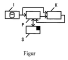
- the figure shows a block diagram of the circuit arrangement according to the invention, the one Possibility of circuitry implementation represents.
- the volume control is used as an exemplary embodiment considered a recipient. It exists especially at Car radios the need controls as possible small to realize because of the space on the front panel is very limited. Therefore, is only a small controller intended for volume. To deal with such Controls a sufficiently precise adjustment of the volume to achieve it is necessary to reach the control range in several turns of the knob on the controller paint over. However, this hinders a quick Setting the volume, for example when Approaching an ambulance or one incoming phone call may be required.
- a rapid turn of the knob does not increase the volume set more proportional to the angle of rotation. It will rather, depending on the direction of rotation stored volume set. Will the knob quickly turned towards lower volume, so the volume is set to zero, the car radio muted. Then the knob turns quickly rotated towards a higher volume, so a medium volume (room volume) or the previous one Volume set. To set a medium Volume, it is necessary that e.g. in the Manufacturing corresponding parameter values for volume and other adjustable parameters in a memory S can be saved. To set the previously selected volume, this is automatically at a most such rapid change into a memory S. registered and at a subsequent second quick turn of the knob in the other direction read out and set again.
- the circuit arrangement for realizing this The process consists of a pulse generator I, which from User is pressed.
- the output signal of the Pulse generator I is fed to a microprocessor which serves as the control unit P of the device.
- this number is replaced by a Comparator K with a stored threshold compared.
- successive output signals of the pulse generator I in the control unit P determined its direction of rotation. If the threshold is exceeded, the reads Control unit P depending on it determined direction of rotation of the encoder I and an extreme value from the Memory S out to which the parameter to be changed is set.
- the memory S is through the Control unit P therefore depending on that changing parameters, the direction of rotation and the previous set value addressed.
Claims (6)
- Procédé de régulation non linéaire de paramètres de fonctionnement, selon lequel la variation du paramètre de fonctionnement s'effectue proportionnellement à l'angle de rotation d'un bouton rotatif, la vitesse de rotation du bouton rotatif est déterminée et le paramètre de fonctionnement est modifié lors de l'actionnement du bouton rotatif en fonction du sens de rotation, caractérisé en ce
que lors de l'actionnement du bouton rotatif et du dépassement d'une valeur de seuil pour la vitesse de rotation, le paramètre de fonctionnement est réglé immédiatement en fonction du sens de rotation et/ou du paramètre précisément réglé, sur une valeur extrême ou sur une valeur de paramètre mémorisée à cet effet. - Procédé selon la revendication 1, caractérisé en ce
que pour la détermination de la vitesse de rotation le nombre d'impulsions par unité de temps du générateur d'impulsions (I) actionné par l'utilisateur au moyen du bouton rotatif, est déterminé. - Procédé selon la revendication 2, caractérisé en ce
qu'on l'utilise pour la régulation de l'intensité acoustique, des aiguës, des basses, et l'équilibre lors de la reproduction à canaux multiples. - Procédé selon la revendication 3, caractérisé en ce
qu'entre la valeur minimale pour le paramètre considéré de fonctionnement et une valeur utilisée fréquemment sont prévues d'autres valeurs intermédiaires pour un réglage rapide, qui sont réglées en fonction de la durée d'actionnement du bouton rotatif. - Montage pour la régulation non linéaire de paramètres de fonctionnement, qui comporte un générateur d'impulsions (I) actionné par l'utilisateur et un circuit pour déterminer le sens de rotation du générateur d'impulsions, dont les signaux de sortie sont envoyés à une unité de commande (P), et dans lequel l'unité de commande (P) comporte un compteur, qui compte les impulsions par unité de temps dans le signal de sortie du générateur d'impulsions (I), caractérisé en ceque l'unité de commande (P) comporte un comparateur (K) qui compare le signal de sortie du compteur à une valeur de seuil lue dans une mémoire (S),qu'il est prévu une mémoire (S) servant à mémoriser des valeurs de seuil, des valeurs extrêmes et des valeurs fréquemment utilisées pour différents paramètres de fonctionnement, etque l'unité de commande (P) comprend des moyens qui, lorsque le quotient d'impulsions par unité de temps dépasse la valeur de seuil mémorisée, lisent l'une des valeurs mémorisées pour le paramètre de fonctionnement sélectionné, en fonction du sens de rotation, à partir de la mémoire (S) et utilisent ces paramètres de fonctionnement pour la poursuite du fonctionnement.
- Montage selon la revendication 5, caractérisé en ce
que l'unité de commande (P) est un microprocesseur.
Applications Claiming Priority (3)
| Application Number | Priority Date | Filing Date | Title |
|---|---|---|---|
| DE4426885A DE4426885C1 (de) | 1994-07-29 | 1994-07-29 | Verfahren und Schaltungsanordnung zur manuellen Eingabe von Betriebsparametern |
| DE4426885 | 1994-07-29 | ||
| PCT/EP1995/002968 WO1996004595A1 (fr) | 1994-07-29 | 1995-07-27 | Procede et circuiterie de regulation non lineaire de parametres de fonctionnement |
Publications (2)
| Publication Number | Publication Date |
|---|---|
| EP0772805A1 EP0772805A1 (fr) | 1997-05-14 |
| EP0772805B1 true EP0772805B1 (fr) | 1999-09-22 |
Family
ID=6524434
Family Applications (1)
| Application Number | Title | Priority Date | Filing Date |
|---|---|---|---|
| EP95928475A Expired - Lifetime EP0772805B1 (fr) | 1994-07-29 | 1995-07-27 | Procede et circuiterie de regulation non lineaire de parametres de fonctionnement |
Country Status (6)
| Country | Link |
|---|---|
| US (1) | US5877710A (fr) |
| EP (1) | EP0772805B1 (fr) |
| JP (1) | JPH10503865A (fr) |
| AT (1) | ATE185005T1 (fr) |
| DE (2) | DE4426885C1 (fr) |
| WO (1) | WO1996004595A1 (fr) |
Families Citing this family (6)
| Publication number | Priority date | Publication date | Assignee | Title |
|---|---|---|---|---|
| JP4474806B2 (ja) * | 2000-07-21 | 2010-06-09 | ソニー株式会社 | 入力装置、再生装置及び音量調整方法 |
| KR100457521B1 (ko) * | 2002-06-04 | 2004-11-17 | 삼성전자주식회사 | 회전 위치 제어 방법 및 장치 |
| JP6291168B2 (ja) * | 2013-04-04 | 2018-03-14 | Pioneer DJ株式会社 | 入力装置、音響機器、入力装置の制御方法およびプログラム |
| JP5716804B2 (ja) * | 2013-09-24 | 2015-05-13 | オンキヨー株式会社 | 数量調整装置 |
| DE102014116075A1 (de) * | 2014-11-04 | 2016-05-04 | Vorwerk & Co. Interholding Gmbh | Elektrisches Küchengerät |
| US11604853B2 (en) | 2019-10-18 | 2023-03-14 | Stmicroelectronics S.R.L. | System and method for performing vector rotation |
Family Cites Families (9)
| Publication number | Priority date | Publication date | Assignee | Title |
|---|---|---|---|---|
| US4203063A (en) * | 1977-08-29 | 1980-05-13 | Rca Corporation | Movement detecting apparatus and method |
| DE2757593C2 (de) * | 1977-12-23 | 1985-09-19 | Licentia Patent-Verwaltungs-Gmbh, 6000 Frankfurt | Digitale Einrichtung zur Einstellung von Zahlen in einer Sicht-Anzeige mittels eines von Hand in unterschiedlichen Richtungen betätigbaren Stellgliedes |
| DE3048991C2 (de) * | 1980-12-24 | 1985-04-25 | Licentia Patent-Verwaltungs-Gmbh, 6000 Frankfurt | Einrichtung zur Eingabe und digitalen Anzeige von Festwerten |
| JPS6221315A (ja) * | 1985-07-22 | 1987-01-29 | Alpine Electron Inc | 音量調整方法 |
| DE3605088A1 (de) * | 1986-02-18 | 1987-11-05 | Bosch Gmbh Robert | Bedieneinrichtung |
| DE3716332A1 (de) * | 1987-05-15 | 1988-11-24 | Grundig Emv | Einknopfbedienung fuer einfachen rangierbetrieb bei videomagnetbandrecordern |
| DE3810744A1 (de) * | 1988-03-30 | 1989-10-12 | Draegerwerk Ag | Digitaler impulsgeber mit einer von der einstellgeschwindigkeit abhaengigen einstelldynamik |
| GB2260966B (en) * | 1991-11-04 | 1994-12-21 | Danby Medical Ltd | Improvements in or relating to electronically controlled infusion devices and arrangements |
| US5189355A (en) * | 1992-04-10 | 1993-02-23 | Ampex Corporation | Interactive rotary controller system with tactile feedback |
-
1994
- 1994-07-29 DE DE4426885A patent/DE4426885C1/de not_active Expired - Fee Related
-
1995
- 1995-07-27 EP EP95928475A patent/EP0772805B1/fr not_active Expired - Lifetime
- 1995-07-27 JP JP8506170A patent/JPH10503865A/ja active Pending
- 1995-07-27 DE DE59506909T patent/DE59506909D1/de not_active Expired - Lifetime
- 1995-07-27 WO PCT/EP1995/002968 patent/WO1996004595A1/fr not_active Application Discontinuation
- 1995-07-27 US US08/776,501 patent/US5877710A/en not_active Expired - Fee Related
- 1995-07-27 AT AT95928475T patent/ATE185005T1/de not_active IP Right Cessation
Also Published As
| Publication number | Publication date |
|---|---|
| ATE185005T1 (de) | 1999-10-15 |
| EP0772805A1 (fr) | 1997-05-14 |
| US5877710A (en) | 1999-03-02 |
| JPH10503865A (ja) | 1998-04-07 |
| DE4426885C1 (de) | 1995-11-16 |
| WO1996004595A1 (fr) | 1996-02-15 |
| DE59506909D1 (de) | 1999-10-28 |
Similar Documents
| Publication | Publication Date | Title |
|---|---|---|
| DE19723645B4 (de) | Anordnung zur Signalübertragung zwischen einer Geberstelle und einer Empfangsstelle | |
| DE102016108206B4 (de) | Schaltungsanordnung und Verfahren zur Dämpfungskompensation in einer Antennensignalverbindung | |
| DE3315150C2 (fr) | ||
| DE2723172B2 (de) | Rauschunterdrückungssystem, insbesondere für Kassetten-Magnetbandgeräte | |
| DE2921556C2 (de) | Einrichtung zur Einstellung eines Bandaufzeichnungsgerätes | |
| DE19734969A1 (de) | Verfahren und Vorrichtung zur Wiedergabe von Audiosignalen | |
| DE3013344A1 (de) | Vorrichtung und verfahren zur verstaerkungssteuerung von eingangssignalen | |
| DE2066199C3 (de) | Radaranlage mit Festzielunterdrückung | |
| EP0772805B1 (fr) | Procede et circuiterie de regulation non lineaire de parametres de fonctionnement | |
| DE19829500A1 (de) | Verfahren zur Verbesserung des Nutzsignals in einer Funkempfangseinheit | |
| DE2921637C2 (de) | Magnetaufzeichnungsvorrichtung | |
| DE2644013A1 (de) | Verfahren und schaltungsanordnung zur phasenentzerrung beim lesen digitaler daten | |
| DE3602509C2 (fr) | ||
| DE2921784C2 (de) | Verfahren und Schaltungsanordnung zur automatischen Einstellung des Vormagnetisierungsstroms für den Sprechkopf eines Tonbandgerätes mit getrennten Köpfen | |
| DE2912575C3 (de) | Schaltungsanordnung zur automatischen Einstellung des Pegels des Vormagnetisierungsstroms für ein Band-Aufzeichnungsgerät | |
| EP1318623B1 (fr) | Méthode pour détecter l'intensité d'un champs électromagnétique | |
| DE2926011C2 (de) | Digitale Amplituden-Steuerschaltung | |
| EP0449370B1 (fr) | Circuit pour rendre les flancs des signaux plus raides | |
| DE2812431A1 (de) | Verstaerker mit veraenderbarem uebertragungsmass | |
| EP0122487B1 (fr) | Appareil pour contrôler la surface de pièces métalliques | |
| DE4208684C2 (de) | Videorekorder mit einer Vorrichtung zur Steuerung eines Kopftrommelwinkels und ein entsprechendes Verfahren | |
| EP0326672A1 (fr) | Méthode et disposition pour la transmission de signaux numériques | |
| EP0214200A1 (fr) | Circuit pour appareil de reproduction de disques audio et de videodisques. | |
| EP0364711B1 (fr) | Circuit de commande du niveau d'un signal | |
| DE4215420C2 (de) | Gehörrichtiger Lautstärkesteuerschaltkreis |
Legal Events
| Date | Code | Title | Description |
|---|---|---|---|
| PUAI | Public reference made under article 153(3) epc to a published international application that has entered the european phase |
Free format text: ORIGINAL CODE: 0009012 |
|
| 17P | Request for examination filed |
Effective date: 19961223 |
|
| AK | Designated contracting states |
Kind code of ref document: A1 Designated state(s): AT DE FR GB IT NL |
|
| RAP1 | Party data changed (applicant data changed or rights of an application transferred) |
Owner name: GRUNDIG AKTIENGESELLSCHAFT |
|
| 17Q | First examination report despatched |
Effective date: 19970801 |
|
| GRAG | Despatch of communication of intention to grant |
Free format text: ORIGINAL CODE: EPIDOS AGRA |
|
| GRAG | Despatch of communication of intention to grant |
Free format text: ORIGINAL CODE: EPIDOS AGRA |
|
| GRAH | Despatch of communication of intention to grant a patent |
Free format text: ORIGINAL CODE: EPIDOS IGRA |
|
| GRAH | Despatch of communication of intention to grant a patent |
Free format text: ORIGINAL CODE: EPIDOS IGRA |
|
| GRAA | (expected) grant |
Free format text: ORIGINAL CODE: 0009210 |
|
| AK | Designated contracting states |
Kind code of ref document: B1 Designated state(s): AT DE FR GB IT NL |
|
| REF | Corresponds to: |
Ref document number: 185005 Country of ref document: AT Date of ref document: 19991015 Kind code of ref document: T |
|
| GBT | Gb: translation of ep patent filed (gb section 77(6)(a)/1977) |
Effective date: 19990922 |
|
| REF | Corresponds to: |
Ref document number: 59506909 Country of ref document: DE Date of ref document: 19991028 |
|
| ET | Fr: translation filed | ||
| ITF | It: translation for a ep patent filed |
Owner name: STUDIO JAUMANN P. & C. S.N.C. |
|
| PLBE | No opposition filed within time limit |
Free format text: ORIGINAL CODE: 0009261 |
|
| STAA | Information on the status of an ep patent application or granted ep patent |
Free format text: STATUS: NO OPPOSITION FILED WITHIN TIME LIMIT |
|
| 26N | No opposition filed | ||
| REG | Reference to a national code |
Ref country code: GB Ref legal event code: IF02 |
|
| REG | Reference to a national code |
Ref country code: FR Ref legal event code: TP |
|
| NLS | Nl: assignments of ep-patents |
Owner name: GRUNDIG MULTIMEDIA B.V. |
|
| PGFP | Annual fee paid to national office [announced via postgrant information from national office to epo] |
Ref country code: NL Payment date: 20090730 Year of fee payment: 15 Ref country code: AT Payment date: 20090724 Year of fee payment: 15 |
|
| REG | Reference to a national code |
Ref country code: NL Ref legal event code: V1 Effective date: 20110201 |
|
| PG25 | Lapsed in a contracting state [announced via postgrant information from national office to epo] |
Ref country code: NL Free format text: LAPSE BECAUSE OF NON-PAYMENT OF DUE FEES Effective date: 20110201 Ref country code: AT Free format text: LAPSE BECAUSE OF NON-PAYMENT OF DUE FEES Effective date: 20100727 |
|
| PGFP | Annual fee paid to national office [announced via postgrant information from national office to epo] |
Ref country code: DE Payment date: 20140805 Year of fee payment: 20 |
|
| PGFP | Annual fee paid to national office [announced via postgrant information from national office to epo] |
Ref country code: FR Payment date: 20140717 Year of fee payment: 20 Ref country code: GB Payment date: 20140717 Year of fee payment: 20 |
|
| PGFP | Annual fee paid to national office [announced via postgrant information from national office to epo] |
Ref country code: IT Payment date: 20140718 Year of fee payment: 20 |
|
| REG | Reference to a national code |
Ref country code: DE Ref legal event code: R071 Ref document number: 59506909 Country of ref document: DE |
|
| REG | Reference to a national code |
Ref country code: GB Ref legal event code: PE20 Expiry date: 20150726 |
|
| PG25 | Lapsed in a contracting state [announced via postgrant information from national office to epo] |
Ref country code: GB Free format text: LAPSE BECAUSE OF EXPIRATION OF PROTECTION Effective date: 20150726 |