EP0771553B1 - Vorrichtung zur Hornhautchirurgie - Google Patents
Vorrichtung zur Hornhautchirurgie Download PDFInfo
- Publication number
- EP0771553B1 EP0771553B1 EP96116809A EP96116809A EP0771553B1 EP 0771553 B1 EP0771553 B1 EP 0771553B1 EP 96116809 A EP96116809 A EP 96116809A EP 96116809 A EP96116809 A EP 96116809A EP 0771553 B1 EP0771553 B1 EP 0771553B1
- Authority
- EP
- European Patent Office
- Prior art keywords
- support
- movement
- drive
- eye
- base ring
- Prior art date
- Legal status (The legal status is an assumption and is not a legal conclusion. Google has not performed a legal analysis and makes no representation as to the accuracy of the status listed.)
- Expired - Lifetime
Links
Images


Classifications
-
- A—HUMAN NECESSITIES
- A61—MEDICAL OR VETERINARY SCIENCE; HYGIENE
- A61F—FILTERS IMPLANTABLE INTO BLOOD VESSELS; PROSTHESES; DEVICES PROVIDING PATENCY TO, OR PREVENTING COLLAPSING OF, TUBULAR STRUCTURES OF THE BODY, e.g. STENTS; ORTHOPAEDIC, NURSING OR CONTRACEPTIVE DEVICES; FOMENTATION; TREATMENT OR PROTECTION OF EYES OR EARS; BANDAGES, DRESSINGS OR ABSORBENT PADS; FIRST-AID KITS
- A61F9/00—Methods or devices for treatment of the eyes; Devices for putting in contact-lenses; Devices to correct squinting; Apparatus to guide the blind; Protective devices for the eyes, carried on the body or in the hand
- A61F9/007—Methods or devices for eye surgery
- A61F9/013—Instruments for compensation of ocular refraction ; Instruments for use in cornea removal, for reshaping or performing incisions in the cornea
Definitions
- the invention relates to a device according to the preamble of patent claim 1.
- This becomes the laminating refractive corneal surgery the radius of curvature of the cornea of a patient's eye Reduced or enlarged in predetermined form by running along a corneal lamella a cut line is completely cut off and removed from the eye. The remaining cornea shows the desired curvature for the after this cut refractive vision correction.
- the desired curvature is indicated by a on the corneal surface applied and appropriately shaped applanation surface. It is accepted that a relatively large cut for vision correction, the cut surface of which remains permanently, is performed on the cornea.
- the device includes among other things, a horizontal guide with a slidably mounted on it Support member, a first linear drive for moving the support member as well a second drive, which is carried by and opposite a platform is vertically adjustable.
- a flat one, for touching one to be operated on anatomical body part sized plate is like this with the second drive connected that it is automatically perpendicular to the platform is adjustable.
- the object of the invention is to provide a device of the type mentioned in the introduction, with which after the corneal treatment on the surface of the cornea before the corneal treatment existing conditions can be restored with simple means are.
- the separated corneal lamella is in the invention via a hinge formed by the corneal tissue with that on the eye remaining cornea connected.
- the corneal lamella can come from the corneal surface can be folded away, so that the stroma for example for laser treatment is exposed.
- the base ring remains on the return stroke of the support that carries the cutting device preferably fixed on the eye by the negative pressure.
- Return stroke of the support and the cutting device the negative pressure in the annular chamber maintained in the area of the cornea, so that a proper fixation of the separated Corneal lamella during the return stroke of the cutting device, in particular the cutting blade.
- the drive of the oscillating knife movement is switched off on the return stroke.
- U.S. Patent 5,133,726 is a cutter known in which the drive of the oscillating knife and the drive the support is coupled with each other, so that a separate control of the drives not possible. This would be particularly disadvantageous when the cutting device is returned, in which according to the invention the knife movement must be switched off, impact.
- the vacuum is switched off, so that the cutting device can be removed from the eye and a subsequent treatment, especially the stroma, after the corneal lamella has been folded away remaining hinge point can be carried out.
- the center of the base ring, to which the knife is attached, is therefore preferred the movable support is guided into the beam path of a movable laser beam aimed at the patient's eye.
- the knife is driven by a separate shaft, and the drive for support is also via a separate Wave.
- Each of the two shafts is driven by an associated motor. hereby ensures that the oscillating drive of the knife and the drive for the advance and retraction movement of the support and thus the advance and retraction movement of the oscillating knife mounted on it can be controlled separately can.
- the two motors are preferably connected to the shaft via flexible shafts Support and the knife connected. This ensures that the cutting instrument into the beam path of a laser ablation device for corneal treatment can be moved before the laser treatment is performed on the patient's eye becomes. The patient does not have to change his position for the treatment.
- the Cutting treatment can therefore be performed on the patient's eye, which is located under the radiation optics of the laser device is carried out and after the cutting process the cutter can be removed.
- the two motors can also be in Form of micromotors can be provided directly on the cutter.
- a piezoelectric linear drive which is preferably supported on the base ring.
- This piezoelectric drive can be designed in a conventional manner (e.g. DE 38 25 587) and composed of piezo actuators.
- three piezo actuators can be provided.
- a suitable piezo drive consists of three piezo crystals, their movement and the linear motion of the support drive coupled to it can be explained by the movement of a tension caterpillar.
- Serve the front and the rear piezo crystal for example, designed as clamping actuators as a brake and the middle piezo crystal, for example a feed actuator of locomotion.
- the first piezo crystal holds the base while the second piezo crystal (middle piezo crystal) expands. So that the arrangement move can, the second brake formed by the third piezo crystal is open.
- the third piezo crystal clamps on the base, in particular the Metal tape, firm, i.e. the second brake is closed while the first Brake, i.e. the first piezo crystal opens and the second piezo crystal (middle piezo crystal) contracts. Then the process repeats itself.
- the type of drive can also be kinematically reversed, i.e. the housing is directly or indirectly with the base ring connected and the pad, for example the metal band, moves and is with connected to support.
- the oscillating knife movements can also be generated by a crystal oscillator his. There is then no need to couple the oscillating knife and the linearly driven supports via flexible shafts connected to motors. The two Drives can then be provided directly on the cutting device.
- the embodiment shown in the figures for a cutter has one Base ring 1, which can be placed on a patient's eye 14 (FIG. 5).
- a support guide in on a frame firmly connected to the base ring 1 Form of two cylindrical guide rods 3.
- the guide rods 3 extend in the Support 2 feed and return direction.
- the knife is in the form of a Blade 11 mounted oscillating.
- the blade 11 carries out an oscillating movement transversely (vertical) to the direction of advance and retraction (double arrow 15) of the support.
- the blade 11 is in a blade guide 16 on one with the base ring 1 connected frame 4 out.
- the drive shaft 5 has an external thread, which in a corresponding internal thread of the support 2 for the feed and return intervenes.
- a second drive shaft 6 is provided for the oscillating drive of the blade 11, which has a bevel gear 17 at its front end, which is in a second bevel gear 7 engages and via a gear not shown in a known manner, e.g. as in DE 34 33 581 shown, with the help of a rotating eccentric the oscillating movement the blade creates.
- the first shaft 5 is via a flexible shaft train 18 with an associated first one Drive motor connected.
- the second drive shaft 6 is also via a flexible shaft train connected to a second drive motor.
- the two engines can be accommodated in a central housing 21.
- the central housing can also be the control device for other components are important during corneal treatment on the patient's eye 14 his.
- a foot switch 22 may be used to turn certain on and off Components, for example for controlling the support feed and the support feed back connected to the central control device accommodated in the housing 21 his.
- FIG. 3 shows an embodiment of a piezo drive, in particular a linear drive, shown for support.
- This linear drive consists of three piezo crystals 34, 35 and 36.
- the front and rear piezo crystals 34 and 36 serve as a brake, and the middle piezo crystal 35 is used for locomotion.
- the three crystals are in one Housing 37 arranged, which is connected to the support.
- the movement takes place on a base 38, which can be designed as a band or rail and directly or indirectly connected to the base ring 1.
- a base 38 which can be designed as a band or rail and directly or indirectly connected to the base ring 1.
- one of the two Rails 3 serve as a base. This will support the linear shift 2 compared to the base ring 1.
- the first is Piezo crystal 34 is firmly connected to the base 38, for example by clamping and acts as a parking brake.
- the second piezo crystal 35 expands from that in the Representation (A) shown in the position shown in representation B from wherein the third piezo crystal 36 is detached from the base 38, so that a displacement into the positions shown in illustrations (B) and (C).
- the piezo crystal 37 is firmly connected to the base 38, while the first Piezo crystal 34 is opened and when the second piezo crystal contracts 35 can advance.
- the housing 37 is in particular in the area of the second piezo crystal 35, flexible.
- Control means which are shown for example in DE 38 25 587.
- FIG. 4 shows a sectional representation of what is placed on the patient's eye 14 Cutter shown.
- the base ring 1 lies on the surface of the eye, and in Area of the eyeball is between the base ring 1 and the eye surface annular chamber 13 formed, which via a pressure-tight line 25 to a closer shown device is connected to generate a negative pressure.
- an annular chamber 12 is formed, which is also pressure-tight Line 26 is connected to a device for generating a negative pressure.
- the devices for generating negative pressure can also be accommodated in the housing 21.
- Between the base ring 1 and the frame 4 is the blade guide 16. At 4, the blade 11 moves from left to right in the guide 16.
- the cutting plane In the cavity of the guide 16 is the cutting plane, in which one Corneal lamella 8 from the eye while maintaining a tissue hinge 9 (FIG. 6) is separated. Due to the negative pressure prevailing in the annular chamber 12 the corneal lamella to be separated is always precisely fixed during the cutting process. Is located above the corneal lamella 8, which is partially separated by incision a sight glass 23 on the frame 4. A crosshair can be located in the sight glass 23, see above that an exact alignment of the cutter with one on the eye before performing of the marking process can be precisely aligned.
- the sight glass 23 On a frame part 4, which is arranged above the blade guide 16, is on the Underside a flat surface 20 is provided. This limits the blade guide up there.
- the sight glass 23 also has a flat surface 19 on its underside flat surface 19 is offset upwards from flat surface 20 on frame part 4, so that the desired depth of cut, measured vertically from the apex of the cornea the corneal tissue for which the corneal lamella can be adjusted.
- the flat surface 19 on the underside of the sight glass 23 runs parallel to the two planes Surfaces on the base ring 1 and on the frame part 4, which limit the blade guide 16.
- the thickness of the flattened shape held under the flat surface 19 of the sight glass 23 corneal lamella 8 to be separated can be adjusted precisely.
- One is preferred Cutting depth of 150 ⁇ m. During the cutting process, it is advantageous to use the feed of the support and thus of the knife always stop when the occasional knife movement in their respective reversal points (speed 0) located.
- a point is provided at which the blade feed or support feed is stopped.
- This point is 24 in FIG. 4 characterized.
- the point 24, which stops the feed movement the blade or the support, is arranged and opposite to treating eye 14 set so that by the cutting process of the Cutting plane in the blade guide 16 not completely delimited corneal lamella 8 is separated, but via the fabric hinge 9 with the one remaining on the eye Cornea 10 remains connected.
- a treatment zone with a certain diameter, preferably 9 mm, are defined.
- the treatment zone which is in the plane of the blade guide, has this diameter 16 lies.
- the corneal lamella 8 projecting beyond this level becomes during of the cutting process partially separated from the eye, whereby, as already explained, the cutting process is stopped at the movement stop point 24, so that the separated Corneal lamella remains connected to the eye via the tissue hinge 9.
- the cutting device with the base ring 1 is on put the eye on and fixed by generating a negative pressure in the chamber 13. Furthermore, a fixing negative pressure is also in the area of the cornea in the annular chamber 12 generated. In this way, the cutter is exactly on the eye in the desired position fixed.
- Switching on the vacuum devices can for example using the foot switch 22. For example, by an acoustic signal can be displayed to the operator that the desired vacuum in the Annular chambers 12 and 13 is present. The pumps used for this can be in the Create a pressure of 0 to 1 bar in the chambers.
- the two drive motors are switched on, so that the Blade an oscillating movement perpendicular to the plane of the drawing in Figure 4 and one Performs feed movement from left to right in Figure 4.
- the support 2 and the blade 11 are then retracted, but the up to Tissue hinge 9 separated corneal lamella 8 due to the negative pressure in the Annular chamber 12 remains fixed.
- the base ring 1 remains in the Chamber 13 maintained negative pressure fixed on the eye.
- the drive for the oscillating cutting movement is switched off. This can by switching off the motor associated with the oscillating cutting movement or by disconnecting a clutch, not shown, between the engine and drive shaft 6.
- the return movement of the support and the blade 11 will mediated by the drive of the other motor associated with the thrust movement.
- the drive spindle 5 then rotates in the direction of rotation reverse to the feed direction.
- the oscillating blade movement can then be stopped or switched off, when the blade has reached the movement stop point 24.
- This movement stopping point can by appropriate control and stopping the associated with the thrust movement Motor in the central control device can be set electronically.
- This Position is determined after the cutter is placed on the eye in the desired position Position is attached.
- a between the drive spindle 5 and the flexible shaft train 18 provided coupling piece 31 serve as an end stop.
- the cutting device After switching off the vacuum, the cutting device is removed from the eye.
- the blade oscillates at 1350 rpm during the cutting process.
- the blade feed rate is 1.3 mm / s.
- the return stroke speed when the oscillation movement is switched off is 3 mm / s.
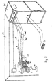
- the base ring 1 can with its center with the aid of the crosshair provided in the sight glass 23 exactly on the Cornea 10 is placed and fixed there with the help of vacuum chambers 12 and 13. This ensures that the cutting device is brought into the area can be in which the beam path is one after the cutting process the laser beam to be directed lies. Because of the flexible drive shafts (flexible shaft piece 18 and flexible shaft 6), which with the stationary in the housing 21 provided drive motors are connected, the cutting device Bring it freely to the desired position in the laser treatment device 27 and remove from there.
- the housing 21 with the control devices located therein can the laser treatment device 27 for corneal treatment, be integrated.
- the patient with his to in a known manner treating eye 14 below a radiation optics 28 on a not shown Laid bed.
- the radiation optics 28 along a fixing line 29 Laser radiation 30 directed onto the eye 14 to be treated.
- the laser radiation 30 onto the exposed one Stroma can be directed.
- the desired refractive corrections are carried out on the eye 14.
- the folded-back corneal lamella 8 will return to its previous one Position returned to the cornea 10, which is exactly the same as before the treatment corresponds to the existing position on the eye.
Landscapes
- Health & Medical Sciences (AREA)
- Ophthalmology & Optometry (AREA)
- Heart & Thoracic Surgery (AREA)
- Surgery (AREA)
- Engineering & Computer Science (AREA)
- Biomedical Technology (AREA)
- Nuclear Medicine, Radiotherapy & Molecular Imaging (AREA)
- Vascular Medicine (AREA)
- Life Sciences & Earth Sciences (AREA)
- Animal Behavior & Ethology (AREA)
- General Health & Medical Sciences (AREA)
- Public Health (AREA)
- Veterinary Medicine (AREA)
- Laser Surgery Devices (AREA)
- Surgical Instruments (AREA)
Description
- Fig. 1:
- ein Ausführungsbeispiel in perspektivischer Darstellung;
- Fig. 2:
- das Ausführungsbeispiel in einer anderen perspektivischen Darstellung;
- Fig. 3:
- ein Ausführungsbeispiel für einen Piezoantrieb;
- Fig. 4:
- eine schnittbildliche Darstellung zur Erläuterung des Schneidvorgangs;
- Fig. 5:
- ein Ausführungsbeispiel, bei dem ein Schneidgerät gemäß den Figuren 1 bis 3 mit einem Lasergerät zur Durchführung chirurgischer Eingriffe an der Augenhomhaut kombiniert ist; und
- Fig. 6:
- eine schematische Darstellung der Hornhautbehandlung nach dem Schnitt.
Claims (19)
- Vorrichtung zur Hornhautchirurgie mit einem auf das zu behandelnde Auge (14) aufsetzbaren und durch Unterdruck fixierbaren Basisring (1), einer Ringkammer (12), in der im Bereich der Hornhaut ein Unterdruck erzeugbar ist, einem oszillierenden Messer (11), das mittels eines auf dem Basisring (1) geführten Supports (2) über das Auge (14) bewegbar ist, und jeweils einem Antrieb für die oszillierende Messerbewegung und die Supportbewegung, wobei der Antrieb für die oszillierende Messerbewegung und der Antrieb für die Supportbewegung in unabhängig voneinander steuerbaren Antriebseinrichtungen (5, 6) bestehen, wobei die Vorrichtung eine zentrale Steuereinrichtung zum elektronischen Steuern und Anhalten des der Supportbewegung zugeordneten Antriebs (5) und des Antriebs (6) der Messerbewegung aufweist,
dadurch gekennzeichnet, daß durch die zentrale Steuereinrichtung ein Bewegungsstop für den Supportvorschub während des Schneidvorgangs an einer Stelle (24) definiert wird, an welcher das von der Hornhaut abgetrennte lamelläre Hornhautstück (8) mit der am Auge (14) verbliebenen Hornhaut über eine vom Hornhautgewebe gebildete Scharnierstelle (9) verbunden ist, so daß das abgetrennte lamelläre Hornhautstück (8) zum Freilegen des darunter befindlichen Augengewebes seitlich wegklappbar ist und daß beim Rückhub des Supports (2) von der Stelle (24) des Bewegungsstops der Antrieb (6) der Messerbewegung durch die zentrale Steuereinrichtung anhaltbar ist. - Vorrichtung nach Anspruch 1, dadurch gekennzeichnet, daß beim Rückhub des Supports (2) der Basisring (1) durch Unterdruck am Auge (14) fixiert bleibt, wobei die Regelung des Unterdrucks durch die zentrale Steuereinrichtung erfolgt.
- Vorrichtung nach Anspruch 1 oder 2, dadurch gekennzeichnet, daß beim Rückhub des Supports (2) der Unterdruck in der Ringkammer (12) im Bereich der Hornhaut aufrechterhalten bleibt, wobei die Regelung des Unterdrucks durch die zentrale Steuereinrichtung erfolgt.
- Vorrichtung nach einem der Ansprüche 1 bis 3, dadurch gekennzeichnet, daß der Antrieb (5) für den Supportvorschub jeweils in den Umkehrpunkten der oszillierenden Messerbewegung durch die zentrale Steuereinrichtung anhaltbar ist.
- Vorrichtung nach einem der Ansprüche 1 bis 4, dadurch gekennzeichnet, daß für den Antrieb (5) des Supports (2) und für den oszillierenden Antrieb (6) des Messers (11) jeweils ein zugeordneter Motor vorgesehen ist.
- Vorrichtung nach einem der Ansprüche 1 bis 5, dadurch gekennzeichnet, daß der Basisring (1) nach Abschalten des Unterdrucks vom Auge (14) abhebbar ist.
- Vorrichtung nach einem der Ansprüche 1 bis 6, dadurch gekennzeichnet, daß der Bewegungsstop (24) im Supportvorschub so angeordnet ist, daß an der Scharnierstelle (9) das Hornhautgewebe eine Dicke von etwa 0,3 mm aufweist.
- Vorrichtung nach einem der Ansprüche 1 bis 7, dadurch gekennzeichnet, daß der Bewegungsstop (24) im Supportvorschub durch einen Festanschlag gesichert ist.
- Vorrichtung nach einem der Ansprüche 1 bis 8, dadurch gekennzeichnet, daß die Schnitttiefe senkrecht in die Hornhaut so bemessen ist, daß das Stroma freigelegt ist.
- Vorrichtung nach einem der Ansprüche 1 bis 9, dadurch gekennzeichnet, daß die über die Ebene einer Klingenführung (16), die parallel zur Ebene des Basisrings (1) liegt, hinausragende und abzutrennende Hornhautlamelle (8) an einer ebenen Fläche (19) anliegt, die parallel zur Ebene der Klingenführung (16) verläuft und entsprechend der Schnitttiefe gegenüber der Ebene der Klingenführung (16) versetzt ist.
- Vorrichtung nach einem der Ansprüche 1 bis 10, dadurch gekennzeichnet, daß für den Vorschub des Supports (2) eine erste Antriebswelle (5) und für die oszillierende Messerbewegung eine zweite Antriebswelle (6) vorgesehen ist.
- Vorrichtung nach Anspruch 11, dadurch gekennzeichnet, daß die erste Antriebswelle (5) von einem ersten Motor und die zweite Antriebswelle (6) von einem zweiten Motor angetrieben sind.
- Vorrichtung nach Anspruch 11 oder 12, dadurch gekennzeichnet, daß die Antriebswellen (5, 6) aus einem flexiblen Material bestehen.
- Vorrichtung nach Anspruch 12 oder 13, dadurch gekennzeichnet, daß die Motoren in einem zentralen Gehäuse (21) angeordnet sind.
- Vorrichtung nach einem der Ansprüche 1 bis 12, dadurch gekennzeichnet, daß die beiden Antriebe für die Supportbewegung und die oszillierende Messerbewegung am Basisring (1) gelagert sind.
- Vorrichtung nach Anspruch 15, dadurch gekennzeichnet, daß der Support (2) von einem piezoelektrischen Linearantrieb (34, 35, 36) angetrieben ist.
- Vorrichtung nach Anspruch 16, dadurch gekennzeichnet, daß der piezoelektrische Linearantrieb (34, 35, 36) des Supports (2) am Basisring (1) abgestützt ist.
- Vorrichtung nach Anspruch 15, dadurch gekennzeichnet, daß ein Schwingkristall, welcher die oszillierende Bewegung des Messers erzeugt, am Support (2) abgestützt ist.
- Vorrichtung nach einem der Ansprüche 1 bis 14, dadurch gekennzeichnet, daß der Basisring (1) mit dem darauf geführten Support (2) mit einem Laserablationsgerät (27) derart kombiniert ist, daß der Basisring (1) mit seiner Mitte in den Bereich bewegbar ist, in welchem der bei der Laserablation auf das freigelegte Stroma gerichtete Laserstrahl (29) verläuft.
Priority Applications (1)
| Application Number | Priority Date | Filing Date | Title |
|---|---|---|---|
| DE19746038A DE19746038C2 (de) | 1996-10-18 | 1997-10-17 | Vorrichtung zur Hornhautchirurgie |
Applications Claiming Priority (2)
| Application Number | Priority Date | Filing Date | Title |
|---|---|---|---|
| DE19540439A DE19540439C2 (de) | 1995-10-30 | 1995-10-30 | Vorrichtung zur Hornhautchirurgie |
| DE19540439 | 1995-10-30 |
Publications (2)
| Publication Number | Publication Date |
|---|---|
| EP0771553A1 EP0771553A1 (de) | 1997-05-07 |
| EP0771553B1 true EP0771553B1 (de) | 2003-08-06 |
Family
ID=7776195
Family Applications (1)
| Application Number | Title | Priority Date | Filing Date |
|---|---|---|---|
| EP96116809A Expired - Lifetime EP0771553B1 (de) | 1995-10-30 | 1996-10-18 | Vorrichtung zur Hornhautchirurgie |
Country Status (4)
| Country | Link |
|---|---|
| US (1) | US5779723A (de) |
| EP (1) | EP0771553B1 (de) |
| DE (2) | DE19540439C2 (de) |
| ES (1) | ES2201146T3 (de) |
Families Citing this family (44)
| Publication number | Priority date | Publication date | Assignee | Title |
|---|---|---|---|---|
| US7166117B2 (en) | 1996-02-07 | 2007-01-23 | Hellenkamp Johann F | Automatic surgical device and control assembly for cutting a cornea |
| DE19746038C2 (de) * | 1996-10-18 | 1999-07-01 | Schwind Gmbh & Co Kg Herbert | Vorrichtung zur Hornhautchirurgie |
| AU716520B2 (en) * | 1996-12-23 | 2000-02-24 | Cesar C. Carriazo | Microkeratome |
| DE69730010T2 (de) * | 1997-04-25 | 2005-09-01 | Krumeich, Jörg H., Dr.med. | Automatische Mikrokeratomieeinrichtung |
| US6126668A (en) * | 1997-04-25 | 2000-10-03 | Innovative Optics, Inc. | Microkeratome |
| US6071293A (en) * | 1997-04-25 | 2000-06-06 | Krumeich; Joerg H. | Automatic microkeratome |
| US6030398A (en) * | 1997-05-30 | 2000-02-29 | Summit Technology, Inc. | Surgical microtomes |
| ES2190516T3 (es) * | 1997-08-06 | 2003-08-01 | Sis Ltd Surgical Instr Systems | Microqueratomo para realizar cirugia de la cornea con laser. |
| FR2767677B1 (fr) * | 1997-09-04 | 1999-11-05 | Moria Sa | Microkeratome pour chirurgie optalmologique |
| US6610075B1 (en) * | 1997-10-24 | 2003-08-26 | Becton, Dickenson And Company | Keratome with suspended stabilized blade, improved suction ring with applanator and guided engagement with keratome cutter head, automated translation of the cutter head, and blade insertion tool |
| WO1999026568A1 (en) | 1997-11-21 | 1999-06-03 | Hawken Industries, Inc. | Opthalmic surgical system and method |
| US6626924B1 (en) | 1998-06-01 | 2003-09-30 | Peter J. Klopotek | Surgical microtomes |
| DE19831674A1 (de) * | 1998-07-15 | 2000-01-20 | Laserforum Gmbh Forum Fuer Las | Refraktivchirurgische Augenhalterung |
| ES2150863B1 (es) * | 1998-08-03 | 2001-06-16 | Novosalud Sl | Microqueratomo para la diseccion de lamelas de tejido corneal. |
| US6090119A (en) | 1998-09-30 | 2000-07-18 | Becton Dickinson And Company | Corneal incision device |
| DE19847089A1 (de) * | 1998-10-13 | 2000-05-31 | Gebauer Gmbh | Augensaugring |
| ATE335448T1 (de) * | 1998-11-05 | 2006-09-15 | Insight Technologies Instr Llc | Keratom und klingenwechsler |
| DE60022413T2 (de) | 1999-03-03 | 2006-01-19 | Nidek Co., Ltd., Gamagori | Operationsvorrichtung für die Kornea |
| US6447526B1 (en) | 1999-03-24 | 2002-09-10 | Cesar C. Carriazo | Disposable microkeratome blade housing |
| US6702832B2 (en) | 1999-07-08 | 2004-03-09 | Med Logics, Inc. | Medical device for cutting a cornea that has a vacuum ring with a slitted vacuum opening |
| US6699285B2 (en) | 1999-09-24 | 2004-03-02 | Scieran Technologies, Inc. | Eye endoplant for the reattachment of a retina |
| JP2001095833A (ja) | 1999-09-30 | 2001-04-10 | Nidek Co Ltd | 角膜手術装置 |
| US6254619B1 (en) | 1999-12-28 | 2001-07-03 | Antoine Garabet | Microkeratome |
| JP3869607B2 (ja) | 2000-01-06 | 2007-01-17 | 株式会社ニデック | 角膜手術装置 |
| US6428508B1 (en) | 2000-02-01 | 2002-08-06 | Enlighten Technologies, Inc. | Pulsed vacuum cataract removal system |
| US6663644B1 (en) | 2000-06-02 | 2003-12-16 | Med-Logics, Inc. | Cutting blade assembly for a microkeratome |
| ATE508717T1 (de) | 2000-09-01 | 2011-05-15 | Alexander Dybbs | Ophthalmisches chirurgisches system |
| FR2815247B1 (fr) * | 2000-10-12 | 2002-12-20 | Moria Sa | Dispositif de chirurgie corneenne |
| US6656133B2 (en) * | 2000-10-13 | 2003-12-02 | Ethicon Endo-Surgery, Inc. | Transmission assembly for a surgical biopsy device |
| DE10051215A1 (de) * | 2000-10-16 | 2002-05-08 | Gebauer Gmbh | Klinge mit amorpher Schneidkante |
| US7311700B2 (en) | 2000-11-29 | 2007-12-25 | Med-Logics, Inc. | LASIK laminar flow system |
| US6425905B1 (en) | 2000-11-29 | 2002-07-30 | Med-Logics, Inc. | Method and apparatus for facilitating removal of a corneal graft |
| TW524683B (en) * | 2001-02-23 | 2003-03-21 | Ras Holding Corp | Surgical blade for use with a surgical tool for making incisions for scleral eye implants |
| EP1581093B1 (de) * | 2002-05-20 | 2011-08-03 | Refocus Group, Inc. | System und verfahren zur bestimmung einer position für eine skleratasche für eine skleraprothese |
| AU2003268558B2 (en) * | 2002-09-09 | 2009-01-08 | Alexander Dybbs | Ophthalmic surgical system |
| CA2521738C (en) * | 2003-04-07 | 2010-09-14 | Bausch & Lomb Incorporated | Bar-link drive system for a microkeratome |
| US7223275B2 (en) * | 2003-05-27 | 2007-05-29 | Yichieh Shiuey | System for cutting the cornea of an eye |
| CN2705138Y (zh) * | 2004-05-26 | 2005-06-22 | 无锡市康明医疗器械有限公司 | 自动眼角膜上皮分离装置 |
| EP1738725A1 (de) * | 2005-06-30 | 2007-01-03 | Wavelight Laser Technologie AG | Einrichtung für die Augenchirurgie |
| DE202007018777U1 (de) * | 2007-02-13 | 2009-05-20 | Schwind Eye-Tech-Solutions Gmbh & Co. Kg | Vorrichtung zum Schneiden einer Hornhaut eines menschlichen oder tierischen Auges |
| EP2092916A1 (de) | 2008-02-19 | 2009-08-26 | Institut National De La Sante Et De La Recherche Medicale (Inserm) | Verfahren zur Behandlung einer Augenkrankheit durch Verabreichung hochintensiven fokussierten Ultraschalls und entsprechende Vorrichtung |
| US8201942B2 (en) * | 2008-04-02 | 2012-06-19 | Refocus Group, Inc. | System and method for identifying a position to insert a scleral prosthesis into an eye |
| US8597318B2 (en) | 2011-08-08 | 2013-12-03 | Refocus Group, Inc. | Apparatus and method for forming incisions in ocular tissue |
| CN111225624A (zh) | 2017-08-23 | 2020-06-02 | 瑞福克斯集团公司 | 一种用于在眼部组织形成切口且具有提供可视性端头的外科手术工具及其相关装置和方法 |
Citations (1)
| Publication number | Priority date | Publication date | Assignee | Title |
|---|---|---|---|---|
| US4903695A (en) * | 1988-11-30 | 1990-02-27 | Lri L.P. | Method and apparatus for performing a keratomileusis or the like operation |
Family Cites Families (11)
| Publication number | Priority date | Publication date | Assignee | Title |
|---|---|---|---|---|
| US4674503A (en) * | 1981-03-05 | 1987-06-23 | Peyman Gholam A | Controlled depth penetrant apparatus and method |
| DE3433581C2 (de) * | 1984-09-13 | 1986-08-07 | Fa. Carl Zeiss, 7920 Heidenheim | Vorrichtung zur lamellierenden, refraktiven Hornhautchirurgie |
| US4840175A (en) * | 1986-12-24 | 1989-06-20 | Peyman Gholam A | Method for modifying corneal curvature |
| DE3825587A1 (de) | 1988-07-28 | 1990-02-01 | Philips Patentverwaltung | Piezoelektrischer linearmotor |
| US5133726A (en) | 1990-02-14 | 1992-07-28 | Ruiz Luis A | Automatic corneal shaper |
| WO1993009738A1 (en) * | 1991-11-21 | 1993-05-27 | Stefano Pintucci | An apparatus to automatically position and operate surgical instruments |
| US5312394A (en) * | 1991-04-29 | 1994-05-17 | Hugh Beckman | Apparatus and method for surgically performing a filtering operation on an eye for glaucoma |
| US5269795A (en) * | 1991-07-03 | 1993-12-14 | Arnott Eric J | Trephine device for removing anterior epithelial cells from corneal surfaces |
| US5496339A (en) * | 1994-05-17 | 1996-03-05 | Koepnick; Russell G. | Universal automated keratectomy apparatus and method |
| US5586980A (en) * | 1994-10-14 | 1996-12-24 | Kremer; Frederic B. | Microkeratome |
| US5643299A (en) * | 1996-01-16 | 1997-07-01 | Sentinel Medical, Inc. | Hydrojet apparatus for refractive surgery |
-
1995
- 1995-10-30 DE DE19540439A patent/DE19540439C2/de not_active Expired - Fee Related
-
1996
- 1996-10-18 EP EP96116809A patent/EP0771553B1/de not_active Expired - Lifetime
- 1996-10-18 ES ES96116809T patent/ES2201146T3/es not_active Expired - Lifetime
- 1996-10-18 DE DE59610644T patent/DE59610644D1/de not_active Expired - Lifetime
- 1996-10-29 US US08/738,582 patent/US5779723A/en not_active Expired - Lifetime
Patent Citations (2)
| Publication number | Priority date | Publication date | Assignee | Title |
|---|---|---|---|---|
| US4903695A (en) * | 1988-11-30 | 1990-02-27 | Lri L.P. | Method and apparatus for performing a keratomileusis or the like operation |
| US4903695C1 (en) * | 1988-11-30 | 2001-09-11 | Lri L P | Method and apparatus for performing a keratomileusis or the like operation |
Non-Patent Citations (1)
| Title |
|---|
| PALLIKARIS ET AL.: "Laser In Situ Keratomileusis", LASERS IN SURGERY AND MEDICINE, vol. 10, no. 5, - 1990, NEW YORK, US, pages 463 - 468 * |
Also Published As
| Publication number | Publication date |
|---|---|
| DE19540439C2 (de) | 1999-04-22 |
| DE59610644D1 (de) | 2003-09-11 |
| US5779723A (en) | 1998-07-14 |
| ES2201146T3 (es) | 2004-03-16 |
| EP0771553A1 (de) | 1997-05-07 |
| DE19540439A1 (de) | 1997-05-15 |
Similar Documents
| Publication | Publication Date | Title |
|---|---|---|
| DE19540439C2 (de) | Vorrichtung zur Hornhautchirurgie | |
| DE69718633T2 (de) | Mikrokeratom zur Hornhautchirurgie mittels Laser | |
| DE69936236T2 (de) | Schneidvorrichtung für ein Keratom | |
| DE69726189T2 (de) | Mikrokeratom | |
| DE10334108B4 (de) | Vorrichtung zum Ausbilden einer geschlossenen, gekrümmten Schnittfläche | |
| DE69511036T2 (de) | Einrichtung zum Vorschieben eines Führungsdrahtes | |
| EP2768447B2 (de) | Erzeugung von schnittflächen in einem transparenten material mittels optischer strahlung | |
| EP1628606B2 (de) | Vorrichtung zum präzisen bearbeiten von material | |
| DE69005285T2 (de) | Automatischer Hornhautschaber. | |
| EP2364681B1 (de) | Vorrichtung zur Materialbearbeitung mittels Laserstrahlung | |
| EP1486185A1 (de) | Opthalmologische Vorrichtung für die Auflösung von Augengewebe | |
| DE69024558T2 (de) | Laser-Abschmelzung von Oberflächen | |
| EP3319569B1 (de) | Ophthalmologische therapieanordnung zur bearbeitung einer fläche in einem bearbeitungsvolumen eines transparenten materials mittels einer fokussierten strahlung | |
| EP2440164A1 (de) | Einrichtung für die laserchirurgische ophthalmologie | |
| WO2008125173A2 (de) | Vorrichtung und verfahren zur materialbearbeitung mittels laserstrahlung | |
| EP1099415A1 (de) | Knochendistraktor mit einer Stelleinrichtung | |
| DE60131466T2 (de) | System für die ophthalmologische chirurgie | |
| DE3615042C2 (de) | Vorrichtung zur Korrektur oder Neugestaltung der Wölbung der Augnhornhaut durch Photoablation von Laserstrahlung | |
| DE60114187T2 (de) | Keratometrische vorrichtung ohne applanationsteil | |
| EP2277481B1 (de) | Lasereinrichtung für die ophthalmologische Chirurgie | |
| DE19746038C2 (de) | Vorrichtung zur Hornhautchirurgie | |
| DE3880050T2 (de) | Abstimmbarer laser-apparat. | |
| WO2010112184A1 (de) | Vorrichtung und verfahren zur entfernung eines lentikels aus der hornhaut | |
| DE102018203358A1 (de) | Planungseinrichtung und -verfahren zur Erzeugung von Steuerdaten für ein ophthalmologisches Lasertherapiegerät für eine Zugangsstruktur | |
| DE69130739T2 (de) | Vorrichtung zum automatischen anbringen und betätigen chirurgischer instrumente |
Legal Events
| Date | Code | Title | Description |
|---|---|---|---|
| PUAI | Public reference made under article 153(3) epc to a published international application that has entered the european phase |
Free format text: ORIGINAL CODE: 0009012 |
|
| AK | Designated contracting states |
Kind code of ref document: A1 Designated state(s): DE ES FR GB IT |
|
| 17P | Request for examination filed |
Effective date: 19970613 |
|
| 17Q | First examination report despatched |
Effective date: 20010525 |
|
| RAP1 | Party data changed (applicant data changed or rights of an application transferred) |
Owner name: SCHWIND EYE-TECH-SOLUTIONS GMBH & CO. KG |
|
| GRAH | Despatch of communication of intention to grant a patent |
Free format text: ORIGINAL CODE: EPIDOS IGRA |
|
| GRAH | Despatch of communication of intention to grant a patent |
Free format text: ORIGINAL CODE: EPIDOS IGRA |
|
| GRAA | (expected) grant |
Free format text: ORIGINAL CODE: 0009210 |
|
| AK | Designated contracting states |
Designated state(s): DE ES FR GB IT |
|
| PG25 | Lapsed in a contracting state [announced via postgrant information from national office to epo] |
Ref country code: IT Free format text: LAPSE BECAUSE OF FAILURE TO SUBMIT A TRANSLATION OF THE DESCRIPTION OR TO PAY THE FEE WITHIN THE PRE;WARNING: LAPSES OF ITALIAN PATENTS WITH EFFECTIVE DATE BEFORE 2007 MAY HAVE OCCURRED AT ANY TIME BEFORE 2007. THE CORRECT EFFECTIVE DATE MAY BE DIFFERENT FROM THE ONE RECORDED.SCRIBED TIME-LIMIT Effective date: 20030806 Ref country code: FR Free format text: LAPSE BECAUSE OF FAILURE TO SUBMIT A TRANSLATION OF THE DESCRIPTION OR TO PAY THE FEE WITHIN THE PRESCRIBED TIME-LIMIT Effective date: 20030806 |
|
| REG | Reference to a national code |
Ref country code: GB Ref legal event code: FG4D Free format text: NOT ENGLISH |
|
| REF | Corresponds to: |
Ref document number: 59610644 Country of ref document: DE Date of ref document: 20030911 Kind code of ref document: P |
|
| GBT | Gb: translation of ep patent filed (gb section 77(6)(a)/1977) |
Effective date: 20031204 |
|
| REG | Reference to a national code |
Ref country code: ES Ref legal event code: FG2A Ref document number: 2201146 Country of ref document: ES Kind code of ref document: T3 |
|
| PLBE | No opposition filed within time limit |
Free format text: ORIGINAL CODE: 0009261 |
|
| STAA | Information on the status of an ep patent application or granted ep patent |
Free format text: STATUS: NO OPPOSITION FILED WITHIN TIME LIMIT |
|
| 26N | No opposition filed |
Effective date: 20040507 |
|
| EN | Fr: translation not filed | ||
| PGFP | Annual fee paid to national office [announced via postgrant information from national office to epo] |
Ref country code: GB Payment date: 20061024 Year of fee payment: 11 |
|
| PGFP | Annual fee paid to national office [announced via postgrant information from national office to epo] |
Ref country code: ES Payment date: 20061025 Year of fee payment: 11 |
|
| GBPC | Gb: european patent ceased through non-payment of renewal fee |
Effective date: 20071018 |
|
| PG25 | Lapsed in a contracting state [announced via postgrant information from national office to epo] |
Ref country code: GB Free format text: LAPSE BECAUSE OF NON-PAYMENT OF DUE FEES Effective date: 20071018 |
|
| REG | Reference to a national code |
Ref country code: ES Ref legal event code: FD2A Effective date: 20071019 |
|
| PG25 | Lapsed in a contracting state [announced via postgrant information from national office to epo] |
Ref country code: ES Free format text: LAPSE BECAUSE OF NON-PAYMENT OF DUE FEES Effective date: 20071019 |
|
| PGFP | Annual fee paid to national office [announced via postgrant information from national office to epo] |
Ref country code: DE Payment date: 20101028 Year of fee payment: 15 |
|
| PG25 | Lapsed in a contracting state [announced via postgrant information from national office to epo] |
Ref country code: DE Free format text: LAPSE BECAUSE OF NON-PAYMENT OF DUE FEES Effective date: 20120501 |
|
| REG | Reference to a national code |
Ref country code: DE Ref legal event code: R119 Ref document number: 59610644 Country of ref document: DE Effective date: 20120501 |