EP0771106B1 - Fernsehtelefonanlage - Google Patents
Fernsehtelefonanlage Download PDFInfo
- Publication number
- EP0771106B1 EP0771106B1 EP96116649A EP96116649A EP0771106B1 EP 0771106 B1 EP0771106 B1 EP 0771106B1 EP 96116649 A EP96116649 A EP 96116649A EP 96116649 A EP96116649 A EP 96116649A EP 0771106 B1 EP0771106 B1 EP 0771106B1
- Authority
- EP
- European Patent Office
- Prior art keywords
- pll circuit
- exposure time
- mains
- camera
- voltage
- Prior art date
- Legal status (The legal status is an assumption and is not a legal conclusion. Google has not performed a legal analysis and makes no representation as to the accuracy of the status listed.)
- Expired - Lifetime
Links
- 238000011156 evaluation Methods 0.000 claims description 2
- 230000015572 biosynthetic process Effects 0.000 description 2
- 230000001276 controlling effect Effects 0.000 description 2
- 230000008878 coupling Effects 0.000 description 2
- 238000010168 coupling process Methods 0.000 description 2
- 238000005859 coupling reaction Methods 0.000 description 2
- 230000001360 synchronised effect Effects 0.000 description 2
- 230000005540 biological transmission Effects 0.000 description 1
- 238000013144 data compression Methods 0.000 description 1
- 238000011161 development Methods 0.000 description 1
- 230000018109 developmental process Effects 0.000 description 1
- 238000010586 diagram Methods 0.000 description 1
- 238000000034 method Methods 0.000 description 1
- 230000000737 periodic effect Effects 0.000 description 1
- 230000001105 regulatory effect Effects 0.000 description 1
- 230000008054 signal transmission Effects 0.000 description 1
Images

Classifications
-
- H—ELECTRICITY
- H04—ELECTRIC COMMUNICATION TECHNIQUE
- H04N—PICTORIAL COMMUNICATION, e.g. TELEVISION
- H04N23/00—Cameras or camera modules comprising electronic image sensors; Control thereof
- H04N23/70—Circuitry for compensating brightness variation in the scene
- H04N23/745—Detection of flicker frequency or suppression of flicker wherein the flicker is caused by illumination, e.g. due to fluorescent tube illumination or pulsed LED illumination
-
- H—ELECTRICITY
- H04—ELECTRIC COMMUNICATION TECHNIQUE
- H04N—PICTORIAL COMMUNICATION, e.g. TELEVISION
- H04N7/00—Television systems
- H04N7/14—Systems for two-way working
- H04N7/141—Systems for two-way working between two video terminals, e.g. videophone
-
- H—ELECTRICITY
- H04—ELECTRIC COMMUNICATION TECHNIQUE
- H04N—PICTORIAL COMMUNICATION, e.g. TELEVISION
- H04N23/00—Cameras or camera modules comprising electronic image sensors; Control thereof
- H04N23/70—Circuitry for compensating brightness variation in the scene
Definitions
- the invention relates to a television telephone system according to the preamble of claim 1.
- a television telephone system also called Videophone
- the amount of light falling from the lens to the target light must be controllable.
- a fixed aperture which, like a shutter, can only be opened or closed electronically.
- the amount of light falling on the target is controlled or regulated by opening this shutter for a time of about 0.5-1 ms, which is short of the image duration.
- the amount of light falling on the target is thus changed electronically by changing the opening time of the shutter.
- Such TV telephone systems work with the signal transmission usually with a data reduction or data compression.
- This consists, for example, in that not the content of an image is transmitted, but only the differences between successive images. It has been found that occurred in a television telephone system with controlled exposure time of the type described by the data reduction errors. In particular, it was found that even with a constant image, ie without differences between successive images, macroblocks were generated in the codec, although there were no changes in the image between successive images. The application of the data reduction for a camera with the said controlled exposure time thus appeared not possible or problematic.
- a television telephone system with a camera according to the preamble of claim 1 is known from TA White et al .: "Subjective assessment of flicker in visualtelephone” Proceedings of the Inst. Of Electrical Engineers, Vol. 121, No. 7, July 1974 (1974-07), pages 594-600 , GB. Out JP 07-264465 and Patent Abstracts of Japan Vol. 1996, No. 02, 29 February 1996 , a camera system is known which avoids interference in the video signal of the camera system caused by the flickering of a discharge lamp.
- the camera of this system is in this case equipped with a flicker sensor which detects periodic intensity fluctuations in the ambient light, and a reference clock signal is generated via a PLL control circuit which controls a shutter of the camera system such that the exposure time is always at the same phase of the mains voltage.
- the invention has the object of providing such a television telephone system in such a way that even in the said operation with controlled exposure time, a data reduction works properly and the generation of superfluous macroblocks is avoided.
- the television telephone system comprises a camera and a shutter opened by a control circuit only during a short exposure time, the signal generated and to be transmitted by the camera being subjected to data reduction by which only changes in the image are transmitted between successive images and Macroblocks are formed for a difference signal.
- the control circuit and the ambient light generating power network are coupled by a PLL circuit such that the exposure time is always at the same phase of the mains voltage.
- a phase rotator In the path of the power network to the PLL circuit is a phase rotator, which is controlled by a microprocessor controlling the camera operation ,
- a television telephone system works mainly with artificial light, in particular of fluorescent tubes.
- the ambient light in the area of the object to be recorded is therefore modulated in brightness at twice the mains frequency, ie 100 Hz, in amplitude, depending on the light source between 30% and 100% or 90% and 100%.
- the refresh rate of the camera is also 50 Hz, it is not coupled in frequency and phase with the mains frequency. Due to small frequency deviations, therefore, the short exposure time, ie the opening time of the shutter, as a rule shifts relative to the line period. In the sense of a beat, therefore, the exposure time is alternately at higher and lower values of the brightness of the ambient light.
- the video signal generated by the camera which is transmitted to the receiving station via the system, is preferably subjected to a data reduction.
- a data reduction This consists e.g. in that only changes in the picture are transmitted between successive pictures. Since experience shows that the changes in the picture are relatively small in a television telephone, the amount of data transmitted can thereby be significantly reduced or a transmission channel can be better utilized.
- the PLL circuit is set so that the exposure time is at the maximum of the mains voltage. This achieves optimum luminous efficacy of the image projected onto the target.
- the mains voltage can be applied galvanically to the PLL circuit.
- a derived from the stray magnetic field of the power supply voltage can be applied to the PLL circuit.
- a brightness sensor in the form of a photodiode for the ambient light may also be provided and connected to the PLL circuit via an evaluation circuit.
- the oscillator of the PLL circuit preferably oscillates at a high frequency compared to the mains frequency, and between the output and an input of the PLL circuit is a frequency divider, which divides the high frequency back to the network and image repetition frequency.
- a PLL circuit with increased oscillator frequency has the advantage of a simpler circuit and greater accuracy. If the camera is not connected to the mains, e.g. works with battery, a voltage at the mains frequency is not available, so that then the information about nominal frequency and nominal phase of the frame rate is missing. In this case, the oscillator of the PLL circuit idles without synchronization through a desired frequency.
- a voltage controlled phase rotator which is controlled by a microprocessor controlling the camera operation. Then the optimal operating point, i. the shutter opening or exposure time at the maximum of the brightness of the ambient light to be set automatically.
- the phase rotation of the phase rotator between 0 and 180 ° is changed continuously while measuring the exposure time set by the processor. The optimum value of the phase rotation is then at the minimum exposure time and can be set to a fixed value.
- Fig. 1 shows the power supply terminals 1 with the mains voltage UN, the power supply unit 2, the voltage-controlled phase rotator 3, the PLL circuit 4 with the VCO oscillator 5, the phase comparator 6 and the externally connected Siebglied 7. Furthermore, the frequency divider 8 for implementing the opposite the high frequency power frequency of the oscillator 5, the signal processor 9, the CCD target 15 containing the controlled shutter, the lens 11, the fluorescent lamp 12 supplied by the mains voltage UN for generating the ambient light L, and the object 13 to be picked up by the camera.
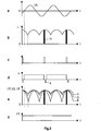
- FIG. 2 shows the amplitude of the brightness of the ambient light L and in the form of the black bars 14 the exposure time or opening time of the shutter, the duration of which is small compared to the network period.
- Fig. 2c shows the pulses that each trigger the opening of the shutter for the CCD target 15.
- Fig. 2d symbolically shows the amplitude of the output signal Y with the vertical sync pulses V in a simplified form for an image without modulation. This is intended to indicate that the amplitude of Y is constant and not undesirably amplitude modulated.
- Fig. 2e shows the intensity of the fluorescence light in the form of the RGB components R, G, B. It can be seen that again the exposure phase relative to the Mains phase is constant and minimal differences occur in the RGB channels.
- Fig. 2f shows in analogy to Fig. 2d the color temperature FT which, like the luminance signal Y, is constant due to the phase coupling.
- the control of the phase rotation of the phase rotator 3 by the microprocessor 10 is as follows.
- the phase rotation of the phase rotator 3 is automatically changed continuously between 0 and 180 °.
- the exposure time of the target 15 set by the microprocessor 10 is measured. If this exposure time has its minimum value, this means that the light output is maximum. At this value, the phase rotation of the phase rotator 3 is then fixed. Then it is ensured that the exposure time according to Fig. 2b always at the maximum of the lighting L is.
Landscapes
- Engineering & Computer Science (AREA)
- Multimedia (AREA)
- Signal Processing (AREA)
- Closed-Circuit Television Systems (AREA)
- Interconnected Communication Systems, Intercoms, And Interphones (AREA)
- Two-Way Televisions, Distribution Of Moving Picture Or The Like (AREA)
- Color Television Image Signal Generators (AREA)
- Studio Devices (AREA)
Applications Claiming Priority (2)
| Application Number | Priority Date | Filing Date | Title |
|---|---|---|---|
| DE19539803A DE19539803A1 (de) | 1995-10-26 | 1995-10-26 | Fernsehtelefonanlage |
| DE19539803 | 1995-10-26 |
Publications (3)
| Publication Number | Publication Date |
|---|---|
| EP0771106A2 EP0771106A2 (de) | 1997-05-02 |
| EP0771106A3 EP0771106A3 (de) | 2001-01-03 |
| EP0771106B1 true EP0771106B1 (de) | 2008-08-13 |
Family
ID=7775793
Family Applications (1)
| Application Number | Title | Priority Date | Filing Date |
|---|---|---|---|
| EP96116649A Expired - Lifetime EP0771106B1 (de) | 1995-10-26 | 1996-10-17 | Fernsehtelefonanlage |
Country Status (5)
| Country | Link |
|---|---|
| US (1) | US5929909A (enExample) |
| EP (1) | EP0771106B1 (enExample) |
| JP (1) | JPH09149393A (enExample) |
| CA (1) | CA2188911C (enExample) |
| DE (2) | DE19539803A1 (enExample) |
Families Citing this family (5)
| Publication number | Priority date | Publication date | Assignee | Title |
|---|---|---|---|---|
| DE10143518A1 (de) * | 2001-09-05 | 2003-03-27 | Siemens Ag | Verfahren und Vorrichtung zur Korrektur von netzspannungsabhängigen Helligkeitsschwankungen bei der Bildaufzeichnung |
| WO2008085815A1 (en) * | 2007-01-05 | 2008-07-17 | Objectvideo, Inc. | Video-based sensing for lighting controls |
| NO331527B1 (no) * | 2009-12-23 | 2012-01-23 | Cisco Systems Int Sarl | Metode for a fjerne flimring i videoopptak |
| CN111839120B (zh) * | 2020-07-27 | 2021-06-25 | 苏州龙时汇达商业设备股份有限公司 | 一种基于互联网直播带货用的可升降商品展示架 |
| EP4141803B1 (en) * | 2021-08-23 | 2024-10-23 | HELLA GmbH & Co. KGaA | System for illuminating the face of an occupant in a car |
Family Cites Families (12)
| Publication number | Priority date | Publication date | Assignee | Title |
|---|---|---|---|---|
| DE2137613B1 (de) * | 1970-10-23 | 1973-02-01 | Siemens AG, 1000 Berlin u 8000 München | Schaltungsanordnung fuer bildfernsprecher zur beseitigung von stoerungen auf dem bildschirm |
| US4076414A (en) * | 1975-02-18 | 1978-02-28 | Tulbert David J | Motion picture printing apparatus |
| US4532550A (en) * | 1984-01-31 | 1985-07-30 | Rca Corporation | Exposure time control for a solid-state color camera |
| US4597015A (en) * | 1984-04-27 | 1986-06-24 | Rca Corporation | Image sensitivity for shuttered solid-state imager television camera |
| NL8403114A (nl) * | 1984-10-12 | 1986-05-01 | Philips Nv | Televisieopneemstelsel dat werkzaam is met van elkaar afwijkende wisselspanningsnetfrekwentie en televisie rasterfrekwentie, en daartoe geschikte televisieopneeminrichting. |
| US4879591A (en) * | 1986-01-31 | 1989-11-07 | Canon Kabushiki Kaisha | Image pickup apparatus compensating an image signal for variations in color temperature |
| JPS63105580A (ja) * | 1986-10-22 | 1988-05-10 | Hitachi Ltd | テレビカメラ |
| US4913547A (en) * | 1988-01-29 | 1990-04-03 | Moran Steven E | Optically phased-locked speckle pattern interferometer |
| DE3831643A1 (de) * | 1988-09-17 | 1990-03-22 | Bosch Gmbh Robert | Gegenseheinrichtung |
| FR2655504B1 (fr) * | 1989-12-01 | 1992-02-21 | Thomson Csf | Procede et dispositif de compression de debit pour camera visiophonique munie d'une matrice photosensible a transfert de charges et systeme de transmission d'images correspondant. |
| JPH0411484A (ja) * | 1990-04-27 | 1992-01-16 | Nippon Philips Kk | 画像表示/撮像装置 |
| JP3091630B2 (ja) * | 1994-03-22 | 2000-09-25 | 三洋電機株式会社 | ビデオカメラ |
-
1995
- 1995-10-26 DE DE19539803A patent/DE19539803A1/de not_active Withdrawn
-
1996
- 1996-09-24 US US08/718,824 patent/US5929909A/en not_active Expired - Lifetime
- 1996-10-17 DE DE59611479T patent/DE59611479D1/de not_active Expired - Lifetime
- 1996-10-17 EP EP96116649A patent/EP0771106B1/de not_active Expired - Lifetime
- 1996-10-21 JP JP8278126A patent/JPH09149393A/ja active Pending
- 1996-10-25 CA CA002188911A patent/CA2188911C/en not_active Expired - Fee Related
Non-Patent Citations (1)
| Title |
|---|
| SAKAE OKUBO: "Reference Model Methodology - A Tool for the Collaborative Creation of Video Coding Standards", PROCEEDINGS OF THE IEEE, vol. 83, no. 2, 1 February 1995 (1995-02-01), USA, pages 139 - 150, XP000501238, DOI: doi:10.1109/5.364470 * |
Also Published As
| Publication number | Publication date |
|---|---|
| JPH09149393A (ja) | 1997-06-06 |
| US5929909A (en) | 1999-07-27 |
| DE59611479D1 (de) | 2008-09-25 |
| DE19539803A1 (de) | 1997-04-30 |
| EP0771106A3 (de) | 2001-01-03 |
| CA2188911A1 (en) | 1997-04-27 |
| EP0771106A2 (de) | 1997-05-02 |
| CA2188911C (en) | 2004-05-11 |
Similar Documents
| Publication | Publication Date | Title |
|---|---|---|
| DE2808600C2 (enExample) | ||
| DE69114972T2 (de) | Festkörper-Bildaufnahmevorrichtungen. | |
| EP0033944B1 (de) | Vorrichtung zur elektronischen Abtastung von Aufnahmegegenständen | |
| DE2107524A1 (de) | Elektronisches System zur Erzeugung eines zusammengesetzten Farbbildes | |
| DE3734957A1 (de) | Logarithmische farbabbildungsvorrichtung | |
| EP0796537A1 (de) | Bildtransferverfahren und -vorrichtung | |
| DE3342335A1 (de) | Digitaler fernsehempfaenger mit analog/digital-umsetzer mit zeitmultiplex-verstaerker | |
| DE10244821A1 (de) | Projektionssystem | |
| DE2316540B2 (de) | Schaltung zur aenderung des dynamischen bereichs eines signals, insbesondere zur stoerverminderung | |
| DE2952947T1 (de) | Pulse modulated automatic light control | |
| DE2805691A1 (de) | Farbfernseh-empfaenger mit automatischem abgleichsystem und verfahren zu seinem abgleich | |
| DE69015997T2 (de) | Fernsehfilmabtaster abgeglichen für negativabtastung. | |
| DE2138883C3 (de) | Gerät zum Umsetzen von Bildinformationen eines Bildinformationsträgers in Videosignale | |
| EP0162311A2 (de) | Steuerschaltung für eine Videokamera und Verfahren zum Steuern einer Videokamera | |
| DE1156637B (de) | Verfahren und elektronisch arbeitende Vorrichtung zum Kopieren von Filmen | |
| DE2951782C2 (de) | Synchronisiersignalgenerator für ein PAL-Farbfernsehsignal-Verarbeitungssystem | |
| DE3048544C2 (enExample) | ||
| EP0771106B1 (de) | Fernsehtelefonanlage | |
| DE1537052B2 (de) | Einrichtung zur Wiedergabe der Bilder eines Filmstreifens mit Hilfe eines Fern sehempfangers | |
| DE3406220C2 (enExample) | ||
| DE2849172A1 (de) | Filmabtaster | |
| DE4230829C2 (de) | On-screen-Anzeigeschaltung | |
| DE2748581C2 (de) | Lichtpunkt-Fernsehfilmabtaster | |
| DE3009507C2 (de) | Einrichtung zur automatischen Regelung der Belichtung für eine Fernsehkamera | |
| DE2612170A1 (de) | Verfahren und schaltungsanordnung zum herstellen eines bildsignaltraegers und damit hergestellte videoplatte |
Legal Events
| Date | Code | Title | Description |
|---|---|---|---|
| PUAI | Public reference made under article 153(3) epc to a published international application that has entered the european phase |
Free format text: ORIGINAL CODE: 0009012 |
|
| AK | Designated contracting states |
Kind code of ref document: A2 Designated state(s): DE FR GB IT |
|
| PUAL | Search report despatched |
Free format text: ORIGINAL CODE: 0009013 |
|
| AK | Designated contracting states |
Kind code of ref document: A3 Designated state(s): DE FR GB IT |
|
| 17P | Request for examination filed |
Effective date: 20010626 |
|
| 17Q | First examination report despatched |
Effective date: 20060929 |
|
| GRAP | Despatch of communication of intention to grant a patent |
Free format text: ORIGINAL CODE: EPIDOSNIGR1 |
|
| RAP1 | Party data changed (applicant data changed or rights of an application transferred) |
Owner name: THOMSON |
|
| RAP1 | Party data changed (applicant data changed or rights of an application transferred) |
Owner name: THOMSON LICENSING, S.A. |
|
| RAP1 | Party data changed (applicant data changed or rights of an application transferred) |
Owner name: THOMSON LICENSING |
|
| GRAS | Grant fee paid |
Free format text: ORIGINAL CODE: EPIDOSNIGR3 |
|
| GRAA | (expected) grant |
Free format text: ORIGINAL CODE: 0009210 |
|
| AK | Designated contracting states |
Kind code of ref document: B1 Designated state(s): DE FR GB IT |
|
| REG | Reference to a national code |
Ref country code: GB Ref legal event code: FG4D Free format text: NOT ENGLISH |
|
| REG | Reference to a national code |
Ref country code: GB Ref legal event code: 746 Effective date: 20080902 |
|
| REF | Corresponds to: |
Ref document number: 59611479 Country of ref document: DE Date of ref document: 20080925 Kind code of ref document: P |
|
| PLBE | No opposition filed within time limit |
Free format text: ORIGINAL CODE: 0009261 |
|
| STAA | Information on the status of an ep patent application or granted ep patent |
Free format text: STATUS: NO OPPOSITION FILED WITHIN TIME LIMIT |
|
| 26N | No opposition filed |
Effective date: 20090514 |
|
| PG25 | Lapsed in a contracting state [announced via postgrant information from national office to epo] |
Ref country code: IT Free format text: LAPSE BECAUSE OF FAILURE TO SUBMIT A TRANSLATION OF THE DESCRIPTION OR TO PAY THE FEE WITHIN THE PRESCRIBED TIME-LIMIT Effective date: 20080813 |
|
| PGFP | Annual fee paid to national office [announced via postgrant information from national office to epo] |
Ref country code: GB Payment date: 20131030 Year of fee payment: 18 Ref country code: DE Payment date: 20131025 Year of fee payment: 18 Ref country code: FR Payment date: 20131017 Year of fee payment: 18 |
|
| REG | Reference to a national code |
Ref country code: DE Ref legal event code: R119 Ref document number: 59611479 Country of ref document: DE |
|
| GBPC | Gb: european patent ceased through non-payment of renewal fee |
Effective date: 20141017 |
|
| PG25 | Lapsed in a contracting state [announced via postgrant information from national office to epo] |
Ref country code: DE Free format text: LAPSE BECAUSE OF NON-PAYMENT OF DUE FEES Effective date: 20150501 Ref country code: GB Free format text: LAPSE BECAUSE OF NON-PAYMENT OF DUE FEES Effective date: 20141017 |
|
| REG | Reference to a national code |
Ref country code: FR Ref legal event code: ST Effective date: 20150630 |
|
| PG25 | Lapsed in a contracting state [announced via postgrant information from national office to epo] |
Ref country code: FR Free format text: LAPSE BECAUSE OF NON-PAYMENT OF DUE FEES Effective date: 20141031 |