EP0769874B1 - Audioverstärkeranordnung für mehr als zwei Wiedergabekanäle - Google Patents
Audioverstärkeranordnung für mehr als zwei Wiedergabekanäle Download PDFInfo
- Publication number
- EP0769874B1 EP0769874B1 EP96115950A EP96115950A EP0769874B1 EP 0769874 B1 EP0769874 B1 EP 0769874B1 EP 96115950 A EP96115950 A EP 96115950A EP 96115950 A EP96115950 A EP 96115950A EP 0769874 B1 EP0769874 B1 EP 0769874B1
- Authority
- EP
- European Patent Office
- Prior art keywords
- reproduction
- channel
- signal
- external loudspeaker
- switching means
- Prior art date
- Legal status (The legal status is an assumption and is not a legal conclusion. Google has not performed a legal analysis and makes no representation as to the accuracy of the status listed.)
- Expired - Lifetime
Links
Images


Classifications
-
- H—ELECTRICITY
- H04—ELECTRIC COMMUNICATION TECHNIQUE
- H04N—PICTORIAL COMMUNICATION, e.g. TELEVISION
- H04N5/00—Details of television systems
- H04N5/44—Receiver circuitry for the reception of television signals according to analogue transmission standards
- H04N5/60—Receiver circuitry for the reception of television signals according to analogue transmission standards for the sound signals
- H04N5/607—Receiver circuitry for the reception of television signals according to analogue transmission standards for the sound signals for more than one sound signal, e.g. stereo, multilanguages
-
- H—ELECTRICITY
- H04—ELECTRIC COMMUNICATION TECHNIQUE
- H04R—LOUDSPEAKERS, MICROPHONES, GRAMOPHONE PICK-UPS OR LIKE ACOUSTIC ELECTROMECHANICAL TRANSDUCERS; ELECTRIC HEARING AIDS; PUBLIC ADDRESS SYSTEMS
- H04R3/00—Circuits for transducers
- H04R3/12—Circuits for transducers for distributing signals to two or more loudspeakers
-
- H—ELECTRICITY
- H04—ELECTRIC COMMUNICATION TECHNIQUE
- H04R—LOUDSPEAKERS, MICROPHONES, GRAMOPHONE PICK-UPS OR LIKE ACOUSTIC ELECTROMECHANICAL TRANSDUCERS; ELECTRIC HEARING AIDS; PUBLIC ADDRESS SYSTEMS
- H04R5/00—Stereophonic arrangements
- H04R5/04—Circuit arrangements, e.g. for selective connection of amplifier inputs/outputs to loudspeakers, for loudspeaker detection, or for adaptation of settings to personal preferences or hearing impairments
-
- H—ELECTRICITY
- H04—ELECTRIC COMMUNICATION TECHNIQUE
- H04R—LOUDSPEAKERS, MICROPHONES, GRAMOPHONE PICK-UPS OR LIKE ACOUSTIC ELECTROMECHANICAL TRANSDUCERS; ELECTRIC HEARING AIDS; PUBLIC ADDRESS SYSTEMS
- H04R2420/00—Details of connection covered by H04R, not provided for in its groups
- H04R2420/03—Connection circuits to selectively connect loudspeakers or headphones to amplifiers
Definitions
- the five speakers mentioned are usually in the form of Loudspeakers can be connected to ensure an appropriate playback quality to reach. Compared to a conventional television set with a stereo sound part this requirement represents a considerable additional effort for the user. For this reason, televisions with a Dolby Pro Logic arrangement generally from the manufacturer without a separate Loudspeakers delivered.
- the device contains internal Housing speakers for reproducing right and left information and the user can choose external to a desired extent Connect loudspeakers.
- the different wiring variants with External speakers require control, which on the one hand certain variants switches off the internal loudspeakers and the on the other hand, the internal speakers are supplied with various signals. While having the problem of turning off the internal speakers Known speaker sockets would be solvable, the problem is different signal supply with such sockets cannot be solved.
- the solution to the problem is made even more difficult by the fact that on the one hand where there are no external speakers either on the center channel or on the side channels are connected, the internal speakers are operated with a signal in the signal processor of the page information center information is superimposed.
- the signal processor must be switched so that a the corresponding overlay is omitted.
- it is advantageous in such an application in which only an external to the center channel Speaker is connected to switch the signal processor so that it the base width and thus the Page information in the side channels is increased.
- the sound part of a television set must have sensible wiring options be switchable between at least five different operating modes. At known televisions is between these modes with the help of device-internal remote control system switched manually. This is circuitry very complex and annoying for the user, because the selection of correct mode of operation not without studying an appropriate one Operating instructions is possible.
- pages 56, 57 are, for example, the television sets ST 63-760 / 9 DPL and ST 72-760 / 9 DPL from Grundig described.
- These devices with the help of an operating software to a surround playback, special Dolby modes, such as Dolby Phantom, Dolby 3 stereo, pseudo surround or be set to normal stereo playback.
- Dolby Phantom Dolby Phantom
- Dolby 3 stereo Dolby 3 stereo
- pseudo surround pseudo surround
- the audio part of these televisions contains a total of six power amplifiers, only five of which can be active at the same time.
- the task of Operating software is limited to Prologic operation and 3 stereo operation each the input of the two power amplifiers for the internal right and left speakers from signal R and L to the center signal depending on the operating mode, the input of the two power amplifiers for the external right and left To separate loudspeakers from signals L and R and the power amplifiers, which are not required according to the selected operating mode, to switch to stand-by mode.
- the operating modes are set via menus independently of the outer speaker circuit.
- the devices have no feedback devices for externally connected devices Speaker. This can result in poor audio playback Consequences if an incorrect menu is set. For example, the internal speakers in Prologic mode and in 3 stereo mode always the center signal, i.e. a mono signal again, even if none external speakers are connected.
- each speaker connection is a specific one Assigned function. It is not possible, for example internal speakers depending on the wiring of the device as a center speaker or to use as a loudspeaker for side information or if there are external center and R, L speakers, these switch off completely.
- the invention is based on an audio amplifier arrangement according to the preamble of claim 1.
- Such an arrangement includes playback channels with audio power amplifiers, internal Speakers and a signal processor that can be switched so that Realize the various playback modes for the playback channels various audio signals are provided.
- the power amplifier contain channel outputs at which you can select the Number and / or assignment of different combinations of sound emitters with the internal loudspeakers and / or external loudspeakers Realize different playback modes can be connected.
- some of the channel outputs have first and second Switching means on when connecting external loudspeakers Carry out the required change of operating mode automatically. Switch in the process the first switching means to the signal processor so that it for certain Power amplifier provides changed audio signals on the input side.
- the second switching means switch the internal speakers between the Channel outputs of different playback channels.
- Playback channel for a surround signal One playback channel for one Right and left side signals and a center signal available.
- the first switching means switches the signal processor into a first operating mode, in the the side signal in the corresponding playback channels Center signal is superimposed when neither on the playback channels for the Side signals still on the center channel an external speaker box connected.
- the first switching means switches the Signal processor in a second mode, in the side signals without Overlay of the center signal are transmitted.
- this embodiment of the audio amplifier arrangement switches the first Switch means the signal processor in a third mode. In this Operating mode broadens the signal processor for the side signals that are on the corresponding playback channels are transmitted, artificially the base width, if there are no external signals on the playback channels for the side signals Speakers and on the playback channel for the center signal external speaker is connected.
- the described embodiment of the invention ensures that the Signal processor, which in the present case is a Dolby Pro Logic Surround processor is, depending on the wiring of the side channels and the Center channel is automatically switched so that it is one for each appropriate wiring performs optimal signal processing.
- the first switching means for switching the signal processor is thereby realizes that the channel outputs of the playback channels for the side signals as well as for the center signal via a resistor network or resistor diode network are connected to a DC voltage, so that Control voltages are available from those on the channel outputs connected impedances of the sound emitters.
- the DC voltage is fed to the channel outputs via impedances, which are more than ten times larger than the impedances of the Sound emitters, which are usually around 8 ohms, so that the level of the Control voltage at a channel output from a high level (H) falls to a low level (L) when an external speaker is connected.
- a corresponding switching logic that is connected to the control section of the adapted signal processor used, evaluates the DC voltage level at the channel outputs and switches the signal processor to required operating mode.
- Another detailed embodiment of the invention relates to the automatic Change the assignment or switch off the internal speakers.
- To the audio amplifier arrangement has second switching means, on the one hand both the internal right and internal left speakers, respectively connect to the playback channel for the corresponding side signal, if there are no external speakers on these playback channels are connected.
- the second switching means connect both internal speakers the playback channel for the center signal when on the playback channels External loudspeakers are connected for the side signals.
- the channel outputs have for connecting external loudspeakers, in particular special speaker switching sockets, which in contrast to known Loudspeaker switching sockets with switches isolated from the channel output are connected. These plug contacts form the second switching means.
- the embodiment relates to a Dolby Surround Sound part for a television set.
- An audio part of a television set not shown, wins a complex television signal, a first audio signal Va1 and a second Audio signal Va2.
- the audio signals Va1 and Va2 are connected to the Signal inputs of a signal processor SP.
- the signal processor SP is a Surround sound processor known per se, which is based on the audio signals Va1 and Va2 each have a side signal Vr and Vl for a right playback channel R. and a left playback channel L and a center signal C for one Playback channel C and a surround signal for a playback channel SR generated.
- Each playback channel R, L, C and SR has an audio power amplifier Ar, Al, Ac and Asr on to sound radiators with a to drive the corresponding signal power.
- the signal processor contains outputs for audio signals and a control input P1 and a control input P2 for switching to a different playback mode.
- the signal processor SP regardless of the control the control inputs P1 and P2, for the playback channel C always on Center signal Vc and always a surround signal for the playback channel SR Vsr generates, the supply of control voltages Vcont1 and Vcont 2 in corresponding logical level combinations that the signal processor SP for the playback channels R and L instead of the side signals Vr and Vl others Generated audio signals.
- a signal Vr + Vc or on Signal Vl + Vc provided for the playback channels R and L
- a signal Vr 'and a signal Vl' is generated.
- the signal processor has opposite the side signals Vr and Vc increases the proportion of the side information. In order to the base width is broadened acoustically during playback.
- the audio amplifier arrangement described so far corresponds to the known ones Solutions.
- the invention is achieved by wiring the channel outputs realized.
- a socket on the channel outputs of the playback channels R and L. Bur or Bul for connecting external loudspeakers Br and Bl.
- Each Bur or Bul socket is mechanically equipped with a changeover switch Sr or Sl coupled in such a way that this from a first switching position to a second Switch position switches when there is a plug in the Bur or Bul socket is introduced.
- the Bur and Bul sockets are designed so that the inserted plug is isolated at least to the closed switching contacts of the switch.
- the switches Sr and Sl of the sockets Bur and Bul with sound emitters in the form of loudspeakers Lr and Ll that are in the television are arranged internally to the right and left of the picture tube.
- Both Switching Sr and Sl is a first switch connection with the Playback channel L or R connected so that the switch contact the Playback channel R or L to the corresponding internal speaker Lr or Ll leads if there is no plug in the socket.
- the aforementioned Bur and Bul sockets is on the channel output for that Center signal Vc connected to a Buc socket, which in conventional Mechanically coupled with an on / off switch.
- the line la is on the one hand to the second switch connection the switch Sr and Sl connected and on the other hand via a resistor R1 connected to a DC voltage + Uo.
- the line la as well as a second line Ib, which goes directly to the channel output for the center signal Vc is connected to serve in conjunction with the resistor network R1, R2 and R3 and the DC voltage + Uo to generate the Control voltages Vcont1 and Vcont2, which the inverter via Inv1 and Inv2 Control inputs P1 and P2 are supplied.
- the two control voltages Vcont1 and Vcont2 are present high level H.
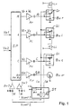
- FIG. 2 shows a section of the audio amplifier arrangement according to the invention.
- external loudspeaker boxes Br and Bl are connected to the channel outputs of the playback channels R and L in this exemplary embodiment.
- the insertion of the plugs from the loudspeaker boxes Br and Bl into the sockets Bur and Bul causes the switches Sr and Sl to be set to the second switching position.
- the internal loudspeakers Lr and Ll automatically connect to line la. This is via switch Sc on playback channel C.
- the external speakers Br and Bl reproduce side information, while the internal speakers Lr and Ll are used to reproduce the center information.
- the two control voltages Vcont1 and Vcont2 are at a low level L. This corresponds to the logical level combination at which the signal processor generates the side signal Vr for the playback channel R and the side signal Vl for the playback channel L.
- FIG. 3 shows an embodiment in which in addition to the external loudspeaker boxes Bsr1 and Bsr2 an external loudspeaker box Bc is connected to the playback of the center signal Vc.
- the Switch Sc the internal speakers Lr and Ll from playback channel C.
Landscapes
- Engineering & Computer Science (AREA)
- Signal Processing (AREA)
- Physics & Mathematics (AREA)
- Acoustics & Sound (AREA)
- Health & Medical Sciences (AREA)
- General Health & Medical Sciences (AREA)
- Otolaryngology (AREA)
- Multimedia (AREA)
- Stereophonic System (AREA)
- Circuit For Audible Band Transducer (AREA)
- Stereophonic Arrangements (AREA)
Description
- je ein Kanal mit Seiteninformation für die Kanäle Rechts (R) und Links (L), zum Betreiben von Lautsprechern, die rechts und links vom Hörer angeordnet sind,
- einen Center-Kanal (C) für Mitteninformation zum Betreiben eines Lautsprechers, der vor dem Hörer mittig angeordnet ist,
- und einen Surround-Kanal (SR) für Umgebungsgeräusche, an dem zwei Lautsprecher angeschlossen sind, die rechts und links hinter dem Hörer angeordnet sind.
- Fig. 1
- eine Prinzipdarstellung einer Audioverstärkeranordnung gemäß der Erfindung, bei der keine externen Lautsprecherboxen angeschlossen sind
- Fig. 2
- eine Prinzipdarstellung einer Audioverstärkeranordnung gemäß der Erfindung, bei der externe Lautsprecherboxen zur Wiedergabe der Seiteninformation angeschlossen sind
- Fig. 3
- eine Prinzipdarstellung einer Audioverstärkeranordnung gemäß der Erfindung, bei der externe Lautsprecherboxen zur Wiedergabe der Center-Information angeschlossen sind
Im Ergebnis dessen geben die externen Lautsprecherboxen Br und Bl Seiteninformation wieder, während die internen Lautsprecher Lr und Ll zur Wiedergabe der Center-Information benutzt werden.
Da bei dieser Wiedergabebetriebsart die niedrige Impedanz der Lautsprecher Lr und Ll mit den Leitungen la und lb verbunden sind, fällt am Widerstand R1 der überwiegende Teil der Gleichspannung +Uo ab. Damit liegen bei dieser Betriebsart die beiden Steuerspannungen Vcont1 und Vcont2 auf niedrigem Pegel L. Dieses entspricht der logischen Pegelkombination, bei der der Signalprozessor für den Wiedergabekanal R das Seitensignal Vr und für den Wiedergabekanal L das Seitensignal Vl generiert.
Claims (7)
- Audioverstärkeranordnung für mehr als zwei Wiedergabekanäle (R, L, C, SR)wobei ein Anschließen von entsprechenden externen Lautsprecherboxen (Br, Bl, Bc) an bestimmte Leistungsverstärker einen Wechsel der Wiedergabebetriebsart erfordert, bei dem sich die Funktion der internen Lautsprecher (Lr, Ll) ändert und/oder der Signalprozessor (SP) umgeschaltet wird,mit einem Signalprozessor (SP), der zum Realisieren verschiedener Wiedergabebetriebsarten umschaltbar ist, um verschiedene Audiosignale (Vr, Vl, Vc, Vsr, Vr+Vc, Vl+Vc) für die Wiedergabekanäle (R, L, C, SR) bereitzustellen,mit internen Lautsprechern (Lr, Ll)und mit Leistungsverstärkern (Ar, Al, Ac, Asr) in den Wiedergabekanälen, an welchen wahlweise verschiedene Kombinationen von Schallstrahlern mit den internen Lautsprechern (Lr, Ll) und/oder mit externen Lautsprecherboxen (Br, Bl, Bc, Bsr1, Bsr2) zum Realisieren der verschiedenen Wiedergabebetriebsarten anschließbar sind,
dadurch gekennzeichnet, daß an den Ausgängen der
Leistungsverstärker erste und zweite Schaltmittel vorhanden sind, die beim Anschließen externer Lautsprecherboxen den erforderlichen Wechsel der Betriebsart selbsttätig ausführen, wobei die ersten Schaltmittel den Signalprozessor umschalten, so daß dieser für bestimmte Leistungsverstärker veränderte Audiosignale bereitstellt und wobei die zweiten Schaltmittel die internen Lautsprecher (Lr, Ll) an verschiedene Ausgänge der Leistungsverstärker schalten. - Audioverstärkeranordnung nach Anspruch 1, dadurch gekennzeichnet,daß mindestens je ein Wiedergabekanal für ein rechtes und ein linkes Seitensignal (Vr, Vl) sowie für ein Center-Signal (Vc) vorhanden sind,daß das erste Schaltmittel (S1) den Signalprozessor (SP) in eine erste Betriebsart schaltet, in der den Seitensignalen (Vr, Vl) das Center-Signal (Vc) überlagert wird, wenn an keinem der drei Wiedergabekanäle eine externe Lautsprecherbox (Br, Bl, Bc) angeschlossen istund daß das erste Schaltmittel (S1) den Signalprozessor (SP) in eine zweite Betriebsart schaltet, in der Seitensignale ohne Überlagerung des Center-Signals übertragen werden, wenn an einem der drei Wiedergabekanäle mindestens eine externe Lautsprecherbox (Br, Bl, Bc) angeschlossen ist.
- Audioverstärkeranordnung nach Anspruch 2, dadurch gekennzeichnet, daß das erste Schaltmittel (S1) den Signalprozessor (SP) in eine dritte Betriebsart schaltet, bei der in der Basisbreite künstlich verbreiterte Seitensignale (Vr', Vl') übertragen werden, wenn an den Wiedergabekanälen für die Seitensignale (Vr, Vl) keine externen Lautsprecherboxen (Br, Bl) und am Wiedergabekanal für das Center-Signal eine externe Lautsprecherbox (Bc) angeschlossen ist.
- Audioverstärkeranordnung nach Anspruch 2, dadurch gekennzeichnet, daß zum Realisieren des ersten Schaltmittels (S1) für das Umschalten des Signalprozessors (SP) die Kanalausgänge der Wiedergabekanäle für die Seitensignale (Vr, Vl) sowie für das Center-Signal (Vc) über ein Widerstandsnetzwerk oder ein Widerstands-Diodennetzwerk mit einer Gleichspannung verbunden sind, so daß Steuerspannungen (Vcont1, Vcont2) verfügbar sind, die einen hohen Pegel (H) aufweisen, wenn am entsprechenden Wiedergabekanal keine externe Lautsprecherbox (Br, Bl, Bc) angeschlossen ist, und die einen niedrigen Pegel (L) aufweisen, wenn am entsprechenden Wiedergabekanal mindestens eine externe Lautsprecherbox (Br, Bl, Bc) angeschlossen ist und daß (SP) eine Schaltlogik vorhanden ist, die den Signalprozessor (SP) entsprechend der logischen Schaltzustände der Steuerspannungen (Vcont1, Vcont2) auf die benötigte Wiedergabebetriebsart umschaltet.
- Audioverstärkeranordnung nach Anspruch 2, dadurch gekennzeichnet,daß die zweiten Schaltmittel (Sr, Sl) jeden der internen Lautsprecher (Lr, Ll) mit dem entsprechenden Wiedergabekanal für die Seitensignale (Vr, Vl) verbinden, wenn an diesen Wiedergabekanälen keine externen Lautsprecherboxen (Br, Bl) angeschlossen sind,und daß die zweiten Schaltmittel (Sr, Sl) beide internen Lautsprecher (Lr, Ll) mit dem Wiedergabekanal für das Center-Signal (Vc) verbinden, wenn an den Wiedergabekanälen für die Seitensignale (Vr, Vl) externe Lautsprecherboxen (Br, Bl) angeschlossen sind.
- Audioverstärkeranordnung nach Anspruch 5, dadurch gekennzeichnet, daß die zweiten Schaltmittel (Sc) die Verbindung zu den internen Lautsprechern (Lr, Ll) öffnen, wenn am Wiedergabekanal für das Center-Signal eine externe Lautsprecherbox (Bc) angeschlossen ist.
- Audioverstärkeranordnung nach Anspruch 5, dadurch gekennzeichnet, daß die Kanalausgänge Steckkontakte (Bur, Bul, Buc) zum Anschließen externer Lautsprecherboxen (Br, Bl, Bc) aufweisen, die mit vom Kanalausgang isolierten Umschaltern derart gekoppelt sind, daß diese beim Anschließen von externen Lautsprecherboxen (Bur, Bul, Buc) betätigt werden und daß diese Umschalter die zweiten Schaltmittel (Sr, Sl, Sc) darstellen.
Applications Claiming Priority (2)
| Application Number | Priority Date | Filing Date | Title |
|---|---|---|---|
| DE19539034A DE19539034A1 (de) | 1995-10-19 | 1995-10-19 | Audioverstärkeranordnung für mehr als zwei Wiedergabekanäle |
| DE19539034 | 1995-10-19 |
Publications (2)
| Publication Number | Publication Date |
|---|---|
| EP0769874A1 EP0769874A1 (de) | 1997-04-23 |
| EP0769874B1 true EP0769874B1 (de) | 2000-12-27 |
Family
ID=7775310
Family Applications (1)
| Application Number | Title | Priority Date | Filing Date |
|---|---|---|---|
| EP96115950A Expired - Lifetime EP0769874B1 (de) | 1995-10-19 | 1996-10-04 | Audioverstärkeranordnung für mehr als zwei Wiedergabekanäle |
Country Status (4)
| Country | Link |
|---|---|
| US (1) | US5757928A (de) |
| EP (1) | EP0769874B1 (de) |
| JP (1) | JP3417770B2 (de) |
| DE (2) | DE19539034A1 (de) |
Families Citing this family (9)
| Publication number | Priority date | Publication date | Assignee | Title |
|---|---|---|---|---|
| US6167140A (en) * | 1997-03-10 | 2000-12-26 | Matsushita Electrical Industrial Co., Ltd. | AV Amplifier |
| CN2382187Y (zh) * | 1999-05-21 | 2000-06-07 | 朱望文 | 模式效果可调校式多用途扬声器装置 |
| JP4712934B2 (ja) * | 2000-03-06 | 2011-06-29 | ソニー株式会社 | 情報信号再生装置 |
| US20020131611A1 (en) * | 2001-03-13 | 2002-09-19 | Hoover Alan Anderson | `Audio surround sound power management switching |
| US6804565B2 (en) * | 2001-05-07 | 2004-10-12 | Harman International Industries, Incorporated | Data-driven software architecture for digital sound processing and equalization |
| JP2003102100A (ja) * | 2001-09-20 | 2003-04-04 | Pioneer Electronic Corp | デジタル音響再生装置、音響装置、および音響再生システム |
| US7489750B1 (en) | 2004-01-15 | 2009-02-10 | Marvell International Ltd. | DC-control for post processor |
| JP2010171647A (ja) * | 2009-01-21 | 2010-08-05 | Sony Corp | 電子機器、電子機器の制御方法及び制御プログラム |
| CN114786108B (zh) * | 2022-03-07 | 2022-12-09 | 深圳市安耐科电子技术有限公司 | 用于单声道功率放大器的配置电路和音频播放设备 |
Family Cites Families (9)
| Publication number | Priority date | Publication date | Assignee | Title |
|---|---|---|---|---|
| JPH0623119Y2 (ja) * | 1989-01-24 | 1994-06-15 | パイオニア株式会社 | サラウンド方式ステレオ再生装置 |
| US5005201A (en) * | 1989-02-14 | 1991-04-02 | Rca Licensing Corporation | Apparatus and method thereof for improvement of stereophonic sound |
| US4905284A (en) * | 1989-02-21 | 1990-02-27 | Concept Enterprises, Inc. | Audio system for vehicular applications |
| DE3926535A1 (de) * | 1989-08-11 | 1991-02-14 | Grundig Emv | Audiowiedergabeeinrichtung mit frequenzselektiven verstaerkern zur ansteuerung geraeteinterner und -externer lautsprecher |
| DE4030121C2 (de) * | 1989-10-11 | 1999-05-12 | Mitsubishi Electric Corp | Mehrkanal-Audiowiedergabevorrichtung |
| JPH03258176A (ja) * | 1990-03-08 | 1991-11-18 | Sharp Corp | テレビジョン受像機 |
| US5161198A (en) * | 1991-05-15 | 1992-11-03 | Allied-Signal Inc. | Mobile radio audio system |
| WO1993025008A1 (en) * | 1992-05-26 | 1993-12-09 | Motorola, Inc. | Radio accessory adapter |
| TW441906U (en) * | 1992-08-28 | 2001-06-16 | Thomson Consumer Electronics | Audio signal processing apparatus and television apparatus |
-
1995
- 1995-10-19 DE DE19539034A patent/DE19539034A1/de not_active Withdrawn
-
1996
- 1996-10-04 EP EP96115950A patent/EP0769874B1/de not_active Expired - Lifetime
- 1996-10-04 DE DE59606252T patent/DE59606252D1/de not_active Expired - Lifetime
- 1996-10-15 US US08/729,328 patent/US5757928A/en not_active Expired - Lifetime
- 1996-10-17 JP JP27477896A patent/JP3417770B2/ja not_active Expired - Fee Related
Also Published As
| Publication number | Publication date |
|---|---|
| DE19539034A1 (de) | 1997-04-24 |
| DE59606252D1 (de) | 2001-02-01 |
| JPH09219899A (ja) | 1997-08-19 |
| US5757928A (en) | 1998-05-26 |
| EP0769874A1 (de) | 1997-04-23 |
| JP3417770B2 (ja) | 2003-06-16 |
Similar Documents
| Publication | Publication Date | Title |
|---|---|---|
| DE68921517T2 (de) | Tonwiedergabegerät. | |
| DE69637455T2 (de) | Automatisch geschaltete entzerrerschaltung | |
| DE3723737C2 (de) | Wiedergabegerät für stereophonische Signale | |
| DE69319392T2 (de) | Abnehmbarer Lautsprecher für Fernsehempfänger | |
| DE2639834C2 (de) | Mehrkanal-Tonaufnahme und -Wiedergabesystem | |
| DE2351423C2 (de) | Stereophonie-Wiedergabegerät | |
| DE2124991C3 (de) | ||
| DE2624568C2 (de) | Stereophones Wiedergabegerät | |
| DE4030121C2 (de) | Mehrkanal-Audiowiedergabevorrichtung | |
| DE3027917A1 (de) | Digitales verstaerkungssteuergeraet | |
| DE2436724C2 (de) | Verstärker-Ausgangsschaltung | |
| EP0769874B1 (de) | Audioverstärkeranordnung für mehr als zwei Wiedergabekanäle | |
| DE19525410A1 (de) | Schaltungsanordnung zum Übertragen von Tonsignalen | |
| DE3107257C2 (de) | Baustein für eine aus wenigstens zwei Bausteinen bestehende Hi-Fi-Anlage | |
| DE3914681A1 (de) | Stereo-expansionsschaltung mit waehlschaltung | |
| DE2532238A1 (de) | Akustisches kombinationsgeraet | |
| DE69327022T2 (de) | Steuerschaltung für Stereofelderweiterungsvorrichtung | |
| DE2728325C2 (de) | ||
| DE3130234A1 (de) | Lautsprecherbox bzw. -kombination fuer stereo-wiedergabe | |
| DE69712926T2 (de) | Stereo zu raumklang nachverstärkung- schalldekodierungsschaltung | |
| EP0074142A2 (de) | Schaltungsanordnung zum Empfangen zweier Modulationssignale, insbesondere beim Fernsehen | |
| DE2802973A1 (de) | Lautsprecher | |
| DE2902819C2 (de) | Lautsprecheranordnung und Schaltung zur Raumklangerzeugung | |
| DE1071762B (de) | ||
| DE3033699C2 (de) | Schaltungsanordnung mit mehreren Signalquellen und einem gemeinsamen Niederfrequenz-Wiedergabeteil |
Legal Events
| Date | Code | Title | Description |
|---|---|---|---|
| PUAI | Public reference made under article 153(3) epc to a published international application that has entered the european phase |
Free format text: ORIGINAL CODE: 0009012 |
|
| AK | Designated contracting states |
Kind code of ref document: A1 Designated state(s): DE FR GB IT |
|
| 17P | Request for examination filed |
Effective date: 19971015 |
|
| GRAG | Despatch of communication of intention to grant |
Free format text: ORIGINAL CODE: EPIDOS AGRA |
|
| GRAG | Despatch of communication of intention to grant |
Free format text: ORIGINAL CODE: EPIDOS AGRA |
|
| GRAH | Despatch of communication of intention to grant a patent |
Free format text: ORIGINAL CODE: EPIDOS IGRA |
|
| 17Q | First examination report despatched |
Effective date: 20000324 |
|
| GRAH | Despatch of communication of intention to grant a patent |
Free format text: ORIGINAL CODE: EPIDOS IGRA |
|
| GRAA | (expected) grant |
Free format text: ORIGINAL CODE: 0009210 |
|
| AK | Designated contracting states |
Kind code of ref document: B1 Designated state(s): DE FR GB IT |
|
| ITF | It: translation for a ep patent filed | ||
| GBT | Gb: translation of ep patent filed (gb section 77(6)(a)/1977) |
Effective date: 20010103 |
|
| REF | Corresponds to: |
Ref document number: 59606252 Country of ref document: DE Date of ref document: 20010201 |
|
| ET | Fr: translation filed | ||
| PLBE | No opposition filed within time limit |
Free format text: ORIGINAL CODE: 0009261 |
|
| STAA | Information on the status of an ep patent application or granted ep patent |
Free format text: STATUS: NO OPPOSITION FILED WITHIN TIME LIMIT |
|
| 26N | No opposition filed | ||
| REG | Reference to a national code |
Ref country code: GB Ref legal event code: IF02 |
|
| PGFP | Annual fee paid to national office [announced via postgrant information from national office to epo] |
Ref country code: GB Payment date: 20090930 Year of fee payment: 14 |
|
| PGFP | Annual fee paid to national office [announced via postgrant information from national office to epo] |
Ref country code: DE Payment date: 20091001 Year of fee payment: 14 |
|
| PGFP | Annual fee paid to national office [announced via postgrant information from national office to epo] |
Ref country code: IT Payment date: 20091016 Year of fee payment: 14 Ref country code: FR Payment date: 20091029 Year of fee payment: 14 |
|
| GBPC | Gb: european patent ceased through non-payment of renewal fee |
Effective date: 20101004 |
|
| PG25 | Lapsed in a contracting state [announced via postgrant information from national office to epo] |
Ref country code: FR Free format text: LAPSE BECAUSE OF NON-PAYMENT OF DUE FEES Effective date: 20101102 |
|
| REG | Reference to a national code |
Ref country code: FR Ref legal event code: ST Effective date: 20110630 |
|
| PG25 | Lapsed in a contracting state [announced via postgrant information from national office to epo] |
Ref country code: GB Free format text: LAPSE BECAUSE OF NON-PAYMENT OF DUE FEES Effective date: 20101004 |
|
| REG | Reference to a national code |
Ref country code: DE Ref legal event code: R119 Ref document number: 59606252 Country of ref document: DE Effective date: 20110502 |
|
| PG25 | Lapsed in a contracting state [announced via postgrant information from national office to epo] |
Ref country code: IT Free format text: LAPSE BECAUSE OF NON-PAYMENT OF DUE FEES Effective date: 20101004 |
|
| PG25 | Lapsed in a contracting state [announced via postgrant information from national office to epo] |
Ref country code: DE Free format text: LAPSE BECAUSE OF NON-PAYMENT OF DUE FEES Effective date: 20110502 |