EP0769681B1 - Wassermengenzähler - Google Patents
Wassermengenzähler Download PDFInfo
- Publication number
- EP0769681B1 EP0769681B1 EP96116454A EP96116454A EP0769681B1 EP 0769681 B1 EP0769681 B1 EP 0769681B1 EP 96116454 A EP96116454 A EP 96116454A EP 96116454 A EP96116454 A EP 96116454A EP 0769681 B1 EP0769681 B1 EP 0769681B1
- Authority
- EP
- European Patent Office
- Prior art keywords
- impeller
- light barrier
- water meter
- reflective
- diode
- Prior art date
- Legal status (The legal status is an assumption and is not a legal conclusion. Google has not performed a legal analysis and makes no representation as to the accuracy of the status listed.)
- Expired - Lifetime
Links
Images

Classifications
-
- G—PHYSICS
- G01—MEASURING; TESTING
- G01F—MEASURING VOLUME, VOLUME FLOW, MASS FLOW OR LIQUID LEVEL; METERING BY VOLUME
- G01F1/00—Measuring the volume flow or mass flow of fluid or fluent solid material wherein the fluid passes through a meter in a continuous flow
- G01F1/05—Measuring the volume flow or mass flow of fluid or fluent solid material wherein the fluid passes through a meter in a continuous flow by using mechanical effects
- G01F1/06—Measuring the volume flow or mass flow of fluid or fluent solid material wherein the fluid passes through a meter in a continuous flow by using mechanical effects using rotating vanes with tangential admission
- G01F1/065—Measuring the volume flow or mass flow of fluid or fluent solid material wherein the fluid passes through a meter in a continuous flow by using mechanical effects using rotating vanes with tangential admission with radiation as transfer means to the indicating device, e.g. light transmission
Definitions
- the invention relates to a water meter with a rotatably mounted in a pressure chamber Impeller, with a scanning device for the impeller, the at least one reflective coating and with a reflection light barrier aligned with the path of the reflection coating.
- One area of application of the invention is the detection of heat consumption in apartments, whose thermal energy is supplied by water.
- energy recording must be carried out and the return temperature the water volume can be measured.
- the temperature measurement is very accurate, however, when measuring the water volume, improvements are sought to improve overall accuracy increase the measurement.
- a water flow meter accommodates an impeller in a pressure-resistant housing flowing water is set in motion.
- the water pressure of a heating system can be up to be over 1.5 MPa.
- a direct passage of the impeller shaft into the pressure-free exterior is due to the high internal pressure and the relatively high friction in the implementation difficult.
- a transmission of the rotary movement into the pressure-free outside space is by magnetic Coupling possible by inductive scanning or by master value acquisition.
- GB 2049925 A describes a flow meter of the generic type. There is the retro-reflective sensor built into the pressure chamber. Such an arrangement is at low pressure medium to be measured applicable. Such an arrangement differs when heating water is recorded due to the high pressures up to 1.5 MPa.
- a similar device is in EP 0163785 B1, described in JP 07055515 A and in US 4851666.
- the magnetite deposits can accommodate that clog the gap to the housing wall.
- the object of the invention is the formation of a minimal energy consumption and also polluted water and reliably working at high pressure of the medium to be detected Scanning the impeller.
- light guides of the reflection light barrier are pressure-tight through the wall of the pressure chamber that the transmitter diode of the infrared light barrier is excited with short pulses and that the receiving transistor has a response delay having.
- the invention differs from the prior art in that the infrared light barrier is effective even with polluted water.
- Light guides enable a pressure-tight passage; a Internal pressure of 2 MPa is permissible without further ado.
- the excitation of the transmitter diode with short pulses and the delayed characteristic of the receiving transistor enables energy-saving operation, so that within the required operating time of 6 years, the energy of a conventional battery is not exhausted becomes.
- a low energy consumption is achieved by clocking the measurement in that the Transmit pulses have a pulse duration of 2 to 20 ⁇ s and a pulse frequency of 100 to 500 Hz.
- a particularly low energy consumption is achieved in that the transmission pulses have a pulse duration of about 3 ⁇ s and a pulse frequency of about 128 Hz.
- the water flow meter has a pressure chamber, of which a wall 1 is shown. In a receptacle 2 of the wall 1, a pin 3 of an impeller 4 is mounted. The other walls and the connection piece of the pressure chamber are not shown.
- the water meter with the Impeller 4 corresponds to the usual design.
- reflection coverings 6 On the end face 5 of the pin 3 there are a plurality of reflection coverings 6 in the form of sector sections.
- On the circular path of the reflection coatings 6 is an infrared light barrier with a transmitter diode 7 and a receiving transistor 8 aligned.
- the transmission diode 7 and the reception transistor 8 are accommodated in an insert body 9.
- the insert body 9 is pressure-tight in the wall 1 of the Pressure chamber installed.
- the reflection coatings can also be arranged elsewhere on the impeller be about on the tips of the wings.
- Another infrared light barrier can be provided offset in the circumferential direction. This is detection of the direction of rotation possible. In addition, vibrations do not result in the hydraulic system to incorrect measurements.
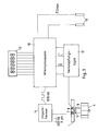
- Fig. 3 shows an overall view of a heat meter with the water meter and the evaluation circuit.
- the optical transmitter diode 7 of the water flow meter is activated with pulses of 3 ⁇ s pulse width and a frequency of 128 Hz excited. These pulses are in the microprocessor 10 generated and shaped in a pulse shaper 11.
- the pulse mode serves to protect the electrical Battery so that long battery operation can be achieved for more than six years.
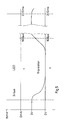
- the receiving transistor 8 is very sensitive to light, but has a low operating frequency. Of the narrow, high-energy transmit pulse switches through the receive transistor with a delay. This on state then remains longer.
- the transmitter diode LED with narrow pulses with a pulse width of 2 - 20 ⁇ s, preferably 3 - 5 ⁇ s and a pulse spacing from 2 - 10 ms, corresponding to 500 - 100 Hz excited.
- the phototransistor has a delayed response and switching through to the line status and pulse stretching up to 500 ms. Thereby secure signal processing is made possible.
- the signals of the multiple light barriers are linked in a logic logic 12 in order to to recognize the direction of rotation and to rule out faults.
- Temperature sensors 13 allow one Heat quantity measurement by the microprocessor 10.
- a display 15 completes the arrangement.
- the insert body comprises light guides 14.
- the transmitting diode 7 and the receiving transistor 8 are located in the outside area. You are therefore always accessible.
Landscapes
- Physics & Mathematics (AREA)
- Fluid Mechanics (AREA)
- General Physics & Mathematics (AREA)
- Measuring Volume Flow (AREA)
- Paper (AREA)
- Optical Transform (AREA)
Description
Claims (4)
- Wassermengenzähler mit einem in einer Druckkammer drehbar gelagerten Flügelrad, mit einer Abtastvorrichtung für das Flügelrad, das mindestens einen Reflexionsbelag aufweist, und mit einer auf die Bahn des Reflexionsbelages ausgerichteten Reflexionslichtschranke, dadurch gekennzeichnet, daß die Reflexionslichtschranke als Infrarotlichtschranke ausgebildet ist, daß Lichtleiter (14) der Reflexionslichtschranke druckdicht durch die Wandung der Druckkammer hindurchgeführt sind, daß die Sendediode der Infrarotlichtschranke mit kurzen Impulsen erregt wird und daß der Empfangstransistor eine Ansprechverzögerung aufweist.
- Wassermengenzähler nach Anspruch 1, dadurch gekennzeichnet, daß die Sendeimpulse eine Impulsdauer von 2 bis 20 µs und eine Impulsfrequenz von 100 bis 500 Hz haben.
- Wassermengenzähler nach Anspruch 2, dadurch gekennzeichnet, daß die Sendeimpulse eine Impulsdauer von etwa 3 µs und eine Impulsfrequenz von etwa 128 Hz haben.
- Wassermengenzähler nach einem der Ansprüche 1 bis 3, dadurch gekennzeichnet, daß mehrere Reflexionsbeläge (6) auf einer Stirnfläche (5) des Zapfens (5) des Flügelrades (4) angeordnet sind.
Applications Claiming Priority (4)
| Application Number | Priority Date | Filing Date | Title |
|---|---|---|---|
| DE19539080 | 1995-10-20 | ||
| DE19539080 | 1995-10-20 | ||
| DE19543361A DE19543361C2 (de) | 1995-10-20 | 1995-11-21 | Wassermengenzähler |
| DE19543361 | 1995-11-21 |
Publications (3)
| Publication Number | Publication Date |
|---|---|
| EP0769681A2 EP0769681A2 (de) | 1997-04-23 |
| EP0769681A3 EP0769681A3 (de) | 1997-11-26 |
| EP0769681B1 true EP0769681B1 (de) | 1998-09-02 |
Family
ID=26019639
Family Applications (1)
| Application Number | Title | Priority Date | Filing Date |
|---|---|---|---|
| EP96116454A Expired - Lifetime EP0769681B1 (de) | 1995-10-20 | 1996-10-15 | Wassermengenzähler |
Country Status (3)
| Country | Link |
|---|---|
| EP (1) | EP0769681B1 (de) |
| AT (1) | ATE170625T1 (de) |
| DK (1) | DK0769681T3 (de) |
Cited By (2)
| Publication number | Priority date | Publication date | Assignee | Title |
|---|---|---|---|---|
| CN106643952A (zh) * | 2017-01-13 | 2017-05-10 | 南安市威速电子科技有限公司 | 一种智能远传液封光电直读水表 |
| CN110260932A (zh) * | 2019-07-03 | 2019-09-20 | 上海在田环境科技有限公司 | 无磁流量计结构及其智能水表 |
Families Citing this family (4)
| Publication number | Priority date | Publication date | Assignee | Title |
|---|---|---|---|---|
| IL158710A0 (en) * | 2003-11-02 | 2004-05-12 | S F M Sophisticated Water Mete | A fluid consumption meter |
| DE102009031694B3 (de) * | 2009-07-04 | 2010-10-14 | Qundis Gmbh | Durchflusszähler |
| CN110260933A (zh) * | 2019-07-03 | 2019-09-20 | 上海在田环境科技有限公司 | 无磁化水管流量检测结构、智能水表及管网流量监测系统 |
| FR3112606B1 (fr) * | 2020-07-17 | 2023-05-05 | Commissariat Energie Atomique | Système à rotor de mesure du débit d’un fluide comportant du liquide, et équipement associé |
Family Cites Families (4)
| Publication number | Priority date | Publication date | Assignee | Title |
|---|---|---|---|---|
| DE2715239A1 (de) * | 1977-04-05 | 1978-10-12 | Georg Aigner | Durchflusszaehler fuer fluessigkeiten |
| DE3608807A1 (de) * | 1986-03-15 | 1987-09-17 | Wolfgang Hopf | Stellungsgeber und dessen verwendung |
| EP0288514A4 (de) * | 1986-10-03 | 1990-01-08 | Conax Buffalo Corp | Faseroptische sensorvorrichtung. |
| US5542302A (en) * | 1995-01-24 | 1996-08-06 | Mcmillan Company | Turbine wheel flow measuring transducer |
-
1996
- 1996-10-15 DK DK96116454T patent/DK0769681T3/da active
- 1996-10-15 EP EP96116454A patent/EP0769681B1/de not_active Expired - Lifetime
- 1996-10-15 AT AT96116454T patent/ATE170625T1/de not_active IP Right Cessation
Cited By (2)
| Publication number | Priority date | Publication date | Assignee | Title |
|---|---|---|---|---|
| CN106643952A (zh) * | 2017-01-13 | 2017-05-10 | 南安市威速电子科技有限公司 | 一种智能远传液封光电直读水表 |
| CN110260932A (zh) * | 2019-07-03 | 2019-09-20 | 上海在田环境科技有限公司 | 无磁流量计结构及其智能水表 |
Also Published As
| Publication number | Publication date |
|---|---|
| EP0769681A2 (de) | 1997-04-23 |
| ATE170625T1 (de) | 1998-09-15 |
| DK0769681T3 (da) | 1999-06-07 |
| EP0769681A3 (de) | 1997-11-26 |
Similar Documents
| Publication | Publication Date | Title |
|---|---|---|
| DE2942421C2 (de) | ||
| EP0769681B1 (de) | Wassermengenzähler | |
| DE2922252A1 (de) | Stroemungsmesser mit impulsgenerator | |
| EP0220595B1 (de) | Elektromagnetischer Impulsaufnehmer für Durchflussmesser | |
| EP0318691A2 (de) | Sensor für Verbrauchsmessungen in einem Haushalts-Verbrauchsmesssystem | |
| DE19543361C2 (de) | Wassermengenzähler | |
| DE102009046653A1 (de) | Magnetisch-induktives Durchflussmesssystem mit beheizbarem Widerstandsthermometer | |
| EP2087322B1 (de) | Volumenzähler für strömende medien mit selektiver kopplung zwischen zähleranordnung und rechenwerk | |
| US5130641A (en) | Eddy wheel edge sensor | |
| WO2011018098A1 (de) | Coriolis-massendurchflussmessgerät | |
| EP0355144B1 (de) | Kombinierter drehzahl/temperatur-messwertaufnehmer | |
| US4831883A (en) | Double bluff body vortex meter | |
| JP2011521218A (ja) | 管の外側壁に接したまたはそのすぐ近くにある少なくとも一つの強磁性物質を有する堆積物の探知方法および装置 | |
| DE3310239C2 (de) | ||
| DE7240626U (de) | Optische drehmessvorrichtung | |
| DE3844294C2 (de) | ||
| JP2501834B2 (ja) | 遠隔計測装置 | |
| CN107923768A (zh) | 借助于线圈和装备有计数器设备的计数器来对转轮的转数计数的设备 | |
| GB2267005A (en) | Data transmission | |
| DE4008844A1 (de) | Volumetrischer zaehler mit schwingendem ringkolben | |
| EP1191310A2 (de) | Turbinendurchflussmesser mit adaptiver Abtastfrequenz | |
| WO2008135182A2 (de) | Berührungslose drehzahlmessung | |
| DE3833145C2 (de) | ||
| DE2829866A1 (de) | Schraubenradzaehler | |
| DE202008007797U1 (de) | Vorrichtung zur Erfassung des Volumenstromes von Medien |
Legal Events
| Date | Code | Title | Description |
|---|---|---|---|
| PUAI | Public reference made under article 153(3) epc to a published international application that has entered the european phase |
Free format text: ORIGINAL CODE: 0009012 |
|
| AK | Designated contracting states |
Kind code of ref document: A2 Designated state(s): AT CH DE DK FI FR LI SE |
|
| PUAL | Search report despatched |
Free format text: ORIGINAL CODE: 0009013 |
|
| AK | Designated contracting states |
Kind code of ref document: A3 Designated state(s): AT CH DE DK FI FR LI SE |
|
| GRAG | Despatch of communication of intention to grant |
Free format text: ORIGINAL CODE: EPIDOS AGRA |
|
| 17P | Request for examination filed |
Effective date: 19980107 |
|
| GRAG | Despatch of communication of intention to grant |
Free format text: ORIGINAL CODE: EPIDOS AGRA |
|
| GRAH | Despatch of communication of intention to grant a patent |
Free format text: ORIGINAL CODE: EPIDOS IGRA |
|
| 17Q | First examination report despatched |
Effective date: 19980305 |
|
| GRAH | Despatch of communication of intention to grant a patent |
Free format text: ORIGINAL CODE: EPIDOS IGRA |
|
| GRAA | (expected) grant |
Free format text: ORIGINAL CODE: 0009210 |
|
| AK | Designated contracting states |
Kind code of ref document: B1 Designated state(s): AT CH DE DK FI FR LI SE |
|
| REF | Corresponds to: |
Ref document number: 170625 Country of ref document: AT Date of ref document: 19980915 Kind code of ref document: T |
|
| REG | Reference to a national code |
Ref country code: CH Ref legal event code: EP |
|
| REF | Corresponds to: |
Ref document number: 59600506 Country of ref document: DE Date of ref document: 19981008 |
|
| ET | Fr: translation filed | ||
| REG | Reference to a national code |
Ref country code: DK Ref legal event code: T3 |
|
| PLBE | No opposition filed within time limit |
Free format text: ORIGINAL CODE: 0009261 |
|
| STAA | Information on the status of an ep patent application or granted ep patent |
Free format text: STATUS: NO OPPOSITION FILED WITHIN TIME LIMIT |
|
| 26N | No opposition filed | ||
| PGFP | Annual fee paid to national office [announced via postgrant information from national office to epo] |
Ref country code: FR Payment date: 19991008 Year of fee payment: 4 |
|
| PGFP | Annual fee paid to national office [announced via postgrant information from national office to epo] |
Ref country code: SE Payment date: 19991021 Year of fee payment: 4 Ref country code: FI Payment date: 19991021 Year of fee payment: 4 Ref country code: DK Payment date: 19991021 Year of fee payment: 4 |
|
| PGFP | Annual fee paid to national office [announced via postgrant information from national office to epo] |
Ref country code: AT Payment date: 19991025 Year of fee payment: 4 |
|
| PGFP | Annual fee paid to national office [announced via postgrant information from national office to epo] |
Ref country code: DE Payment date: 19991230 Year of fee payment: 4 |
|
| PG25 | Lapsed in a contracting state [announced via postgrant information from national office to epo] |
Ref country code: FI Free format text: LAPSE BECAUSE OF NON-PAYMENT OF DUE FEES Effective date: 20001015 Ref country code: DK Free format text: LAPSE BECAUSE OF NON-PAYMENT OF DUE FEES Effective date: 20001015 Ref country code: AT Free format text: LAPSE BECAUSE OF NON-PAYMENT OF DUE FEES Effective date: 20001015 |
|
| PG25 | Lapsed in a contracting state [announced via postgrant information from national office to epo] |
Ref country code: SE Free format text: THE PATENT HAS BEEN ANNULLED BY A DECISION OF A NATIONAL AUTHORITY Effective date: 20001030 |
|
| PG25 | Lapsed in a contracting state [announced via postgrant information from national office to epo] |
Ref country code: LI Free format text: LAPSE BECAUSE OF NON-PAYMENT OF DUE FEES Effective date: 20001031 Ref country code: CH Free format text: LAPSE BECAUSE OF NON-PAYMENT OF DUE FEES Effective date: 20001031 |
|
| REG | Reference to a national code |
Ref country code: DK Ref legal event code: EBP |
|
| REG | Reference to a national code |
Ref country code: CH Ref legal event code: PL |
|
| EUG | Se: european patent has lapsed |
Ref document number: 96116454.8 |
|
| PG25 | Lapsed in a contracting state [announced via postgrant information from national office to epo] |
Ref country code: FR Free format text: LAPSE BECAUSE OF NON-PAYMENT OF DUE FEES Effective date: 20010629 |
|
| PG25 | Lapsed in a contracting state [announced via postgrant information from national office to epo] |
Ref country code: DE Free format text: LAPSE BECAUSE OF NON-PAYMENT OF DUE FEES Effective date: 20010703 |
|
| REG | Reference to a national code |
Ref country code: FR Ref legal event code: ST |