EP0769681B1 - Water meter - Google Patents
Water meter Download PDFInfo
- Publication number
- EP0769681B1 EP0769681B1 EP96116454A EP96116454A EP0769681B1 EP 0769681 B1 EP0769681 B1 EP 0769681B1 EP 96116454 A EP96116454 A EP 96116454A EP 96116454 A EP96116454 A EP 96116454A EP 0769681 B1 EP0769681 B1 EP 0769681B1
- Authority
- EP
- European Patent Office
- Prior art keywords
- impeller
- light barrier
- water meter
- reflective
- diode
- Prior art date
- Legal status (The legal status is an assumption and is not a legal conclusion. Google has not performed a legal analysis and makes no representation as to the accuracy of the status listed.)
- Expired - Lifetime
Links
Images

Classifications
-
- G—PHYSICS
- G01—MEASURING; TESTING
- G01F—MEASURING VOLUME, VOLUME FLOW, MASS FLOW OR LIQUID LEVEL; METERING BY VOLUME
- G01F1/00—Measuring the volume flow or mass flow of fluid or fluent solid material wherein the fluid passes through a meter in a continuous flow
- G01F1/05—Measuring the volume flow or mass flow of fluid or fluent solid material wherein the fluid passes through a meter in a continuous flow by using mechanical effects
- G01F1/06—Measuring the volume flow or mass flow of fluid or fluent solid material wherein the fluid passes through a meter in a continuous flow by using mechanical effects using rotating vanes with tangential admission
- G01F1/065—Measuring the volume flow or mass flow of fluid or fluent solid material wherein the fluid passes through a meter in a continuous flow by using mechanical effects using rotating vanes with tangential admission with radiation as transfer means to the indicating device, e.g. light transmission
Definitions
- the invention relates to a water meter with a rotatably mounted in a pressure chamber Impeller, with a scanning device for the impeller, the at least one reflective coating and with a reflection light barrier aligned with the path of the reflection coating.
- One area of application of the invention is the detection of heat consumption in apartments, whose thermal energy is supplied by water.
- energy recording must be carried out and the return temperature the water volume can be measured.
- the temperature measurement is very accurate, however, when measuring the water volume, improvements are sought to improve overall accuracy increase the measurement.
- a water flow meter accommodates an impeller in a pressure-resistant housing flowing water is set in motion.
- the water pressure of a heating system can be up to be over 1.5 MPa.
- a direct passage of the impeller shaft into the pressure-free exterior is due to the high internal pressure and the relatively high friction in the implementation difficult.
- a transmission of the rotary movement into the pressure-free outside space is by magnetic Coupling possible by inductive scanning or by master value acquisition.
- GB 2049925 A describes a flow meter of the generic type. There is the retro-reflective sensor built into the pressure chamber. Such an arrangement is at low pressure medium to be measured applicable. Such an arrangement differs when heating water is recorded due to the high pressures up to 1.5 MPa.
- a similar device is in EP 0163785 B1, described in JP 07055515 A and in US 4851666.
- the magnetite deposits can accommodate that clog the gap to the housing wall.
- the object of the invention is the formation of a minimal energy consumption and also polluted water and reliably working at high pressure of the medium to be detected Scanning the impeller.
- light guides of the reflection light barrier are pressure-tight through the wall of the pressure chamber that the transmitter diode of the infrared light barrier is excited with short pulses and that the receiving transistor has a response delay having.
- the invention differs from the prior art in that the infrared light barrier is effective even with polluted water.
- Light guides enable a pressure-tight passage; a Internal pressure of 2 MPa is permissible without further ado.
- the excitation of the transmitter diode with short pulses and the delayed characteristic of the receiving transistor enables energy-saving operation, so that within the required operating time of 6 years, the energy of a conventional battery is not exhausted becomes.
- a low energy consumption is achieved by clocking the measurement in that the Transmit pulses have a pulse duration of 2 to 20 ⁇ s and a pulse frequency of 100 to 500 Hz.
- a particularly low energy consumption is achieved in that the transmission pulses have a pulse duration of about 3 ⁇ s and a pulse frequency of about 128 Hz.
- the water flow meter has a pressure chamber, of which a wall 1 is shown. In a receptacle 2 of the wall 1, a pin 3 of an impeller 4 is mounted. The other walls and the connection piece of the pressure chamber are not shown.
- the water meter with the Impeller 4 corresponds to the usual design.
- reflection coverings 6 On the end face 5 of the pin 3 there are a plurality of reflection coverings 6 in the form of sector sections.
- On the circular path of the reflection coatings 6 is an infrared light barrier with a transmitter diode 7 and a receiving transistor 8 aligned.
- the transmission diode 7 and the reception transistor 8 are accommodated in an insert body 9.
- the insert body 9 is pressure-tight in the wall 1 of the Pressure chamber installed.
- the reflection coatings can also be arranged elsewhere on the impeller be about on the tips of the wings.
- Another infrared light barrier can be provided offset in the circumferential direction. This is detection of the direction of rotation possible. In addition, vibrations do not result in the hydraulic system to incorrect measurements.
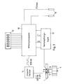
- Fig. 3 shows an overall view of a heat meter with the water meter and the evaluation circuit.
- the optical transmitter diode 7 of the water flow meter is activated with pulses of 3 ⁇ s pulse width and a frequency of 128 Hz excited. These pulses are in the microprocessor 10 generated and shaped in a pulse shaper 11.
- the pulse mode serves to protect the electrical Battery so that long battery operation can be achieved for more than six years.
- the receiving transistor 8 is very sensitive to light, but has a low operating frequency. Of the narrow, high-energy transmit pulse switches through the receive transistor with a delay. This on state then remains longer.
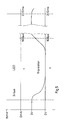
- the transmitter diode LED with narrow pulses with a pulse width of 2 - 20 ⁇ s, preferably 3 - 5 ⁇ s and a pulse spacing from 2 - 10 ms, corresponding to 500 - 100 Hz excited.
- the phototransistor has a delayed response and switching through to the line status and pulse stretching up to 500 ms. Thereby secure signal processing is made possible.
- the signals of the multiple light barriers are linked in a logic logic 12 in order to to recognize the direction of rotation and to rule out faults.
- Temperature sensors 13 allow one Heat quantity measurement by the microprocessor 10.
- a display 15 completes the arrangement.
- the insert body comprises light guides 14.
- the transmitting diode 7 and the receiving transistor 8 are located in the outside area. You are therefore always accessible.
Abstract
Description
Die Erfindung betrifft einen Wassermengenzähler mit einem in einer Druckkammer drehbar gelagerten Flügelrad, mit einer Abtastvorrichtung für das Flügelrad, das mindestens einen Reflexionsbelag aufweist, und mit einer auf die Bahn des Reflexionsbelages ausgerichteten Reflexionslichtschranke.The invention relates to a water meter with a rotatably mounted in a pressure chamber Impeller, with a scanning device for the impeller, the at least one reflective coating and with a reflection light barrier aligned with the path of the reflection coating.
Ein Anwendungsgebiet der Erfindung ist die Erfassung des Wärmeverbrauchs in Wohnungen, deren Wärmeenergie durch Wasser zugeführt wird. Zur Energieerfassung muß neben der Vorlauftemperatur und der Rücklauftemperatur das Wasservolumen gemessen werden. Die Temperaturmessung ist sehr genau, jedoch werden bei der Messung des Wasservolumens Verbesserungen erstrebt, um die Gesamtgenauigkeit der Messung zu erhöhen.One area of application of the invention is the detection of heat consumption in apartments, whose thermal energy is supplied by water. In addition to the flow temperature, energy recording must be carried out and the return temperature the water volume can be measured. The temperature measurement is very accurate, however, when measuring the water volume, improvements are sought to improve overall accuracy increase the measurement.
Ein Wassermengenzähler nimmt in einem druckfesten Gehäuse ein Flügelrad auf, das von dem durchströmenden Wasser in Bewegung gesetzt wird. Der Wasserdruck einer Heizungsanlage kann bis über 1,5 MPa betragen. Eine direkte Durchführung der Welle des Flügelrades in den druckfreien Außenraum ist wegen des hohen Innendrucks und der verhältnismäßig hohen Reibung in der Durchführung schwierig.A water flow meter accommodates an impeller in a pressure-resistant housing flowing water is set in motion. The water pressure of a heating system can be up to be over 1.5 MPa. A direct passage of the impeller shaft into the pressure-free exterior is due to the high internal pressure and the relatively high friction in the implementation difficult.
Eine Übertragung der Drehbewegung in den druckfreien Außenraum ist durch magnetische Kopplung, durch induktive Abtastung oder durch Leitwerterfassung möglich.A transmission of the rotary movement into the pressure-free outside space is by magnetic Coupling possible by inductive scanning or by master value acquisition.
Die DE 3608807 Al beschreibt eine induktive Abtastung. Diese ist störanfällig und wegen der Forderung nach elektromagnetischer Verträglichkeit kritisch.DE 3608807 A1 describes an inductive scanning. This is prone to failure and because of Critical demand for electromagnetic compatibility.
Eine Leitwerterfassung scheidet infolge der großen Änderung des Leitwertes in Heizungswasser (pH-Werte zwischen 5 und 11 sind zulässig) aus.Conductivity detection is not possible due to the large change in the conductance in heating water (pH values between 5 and 11 are permissible).
Das DE 8909930 U1 beschreibt einen Durchflußmesser mit Taktgeberelementen auf dem Rotor und mit einem Sensor in der Wandung des Geräts. Eine Anpassung an verschmutztes Heizungswasser und an einen geringen Energieverbrauch ist dieser Druckschrift nicht entnehmbar. DE 8909930 U1 describes a flow meter with clock elements on the rotor and with a sensor in the wall of the device. An adaptation to dirty heating water and this document cannot be deduced from a low energy consumption.
Die GB 2049925 A beschreibt einen Durchflußmesser der gattungsgemäßen Art. Dort ist die Reflexionslichtschranke in den Druckraum eingebaut. Eine derartige Anordnung ist bei geringem Druck des zu messenden Mediums anwendbar. Bei der Erfassung von Heizungswasser scheidet eine solche Anordnung infolge der hohen Drücke bis zu 1,5 MPa aus. Eine ähnliche Vorrichtung ist in der EP 0163785 B1, in der JP 07055515 A und in der US 4851666 beschrieben.GB 2049925 A describes a flow meter of the generic type. There is the retro-reflective sensor built into the pressure chamber. Such an arrangement is at low pressure medium to be measured applicable. Such an arrangement differs when heating water is recorded due to the high pressures up to 1.5 MPa. A similar device is in EP 0163785 B1, described in JP 07055515 A and in US 4851666.
Für eine magnetische Kopplung ist an dem Flügelrad ein Magnet erforderlich, der Magnetitablagerungen aufnehmen kann, die den Spalt zu der Gehäusewand zusetzen.For a magnetic coupling, a magnet is required on the impeller, the magnetite deposits can accommodate that clog the gap to the housing wall.
Aufgabe der Erfindung ist die Ausbildung einer bei minimalem Energieverbrauch und auch bei verschmutztem Wasser sowie bei hohem Druck des zu erfassenden Mediums zuverlässig arbeitenden Abtastung des Flügelrades.The object of the invention is the formation of a minimal energy consumption and also polluted water and reliably working at high pressure of the medium to be detected Scanning the impeller.
Diese Aufgabe wird nach der Erfindung dadurch gelöst, daß Lichtleiter der Reflexionslichtschranke druckdicht durch die Wandung der Druckkammer hindurchgeführt sind, daß die Sendediode der Infrarotlichtschranke mit kurzen Impulsen erregt wird und daß der Empfangstransistor eine Ansprechverzögerung aufweist.This object is achieved according to the invention in that light guides of the reflection light barrier are pressure-tight through the wall of the pressure chamber that the transmitter diode of the infrared light barrier is excited with short pulses and that the receiving transistor has a response delay having.
Die Erfindung unterscheidet sich insofern vom Stand der Technik, als die Infratolichtschranke auch bei verschmutztem Wasser wirksam ist. Lichtleiter ermöglichen eine durckdichte Durchführung; ein Innendruck von 2 MPa ist ohne weiteres zulässig. Die Erregung der Sendediode mit kurzen Impulsen und die verzögerte Charakteristik des Empfangstransistors ermöglichen einen energiesparenden Betrieb, so daß innnerhalb der geforderten Betriebszeit von 6 Jahren, die Energie einer üblichen Batterie nicht erschöpft wird.The invention differs from the prior art in that the infrared light barrier is effective even with polluted water. Light guides enable a pressure-tight passage; a Internal pressure of 2 MPa is permissible without further ado. The excitation of the transmitter diode with short pulses and the delayed characteristic of the receiving transistor enables energy-saving operation, so that within the required operating time of 6 years, the energy of a conventional battery is not exhausted becomes.
Eine geringer Energieverbrauch wird durch eine Taktung der Messung dadurch erreicht, daß die Sendeimpulse eine Impulsdauer von 2 bis 20 µs und eine Impulsfrequenz von 100 bis 500 Hz haben.A low energy consumption is achieved by clocking the measurement in that the Transmit pulses have a pulse duration of 2 to 20 µs and a pulse frequency of 100 to 500 Hz.
Ein besonders geringer Energieverbrauch wird dadurch erreicht, daß die Sendeimpulse eine Impulsdauer von etwa 3 µs und eine Impulsfrequenz von etwa 128 Hz haben.A particularly low energy consumption is achieved in that the transmission pulses have a pulse duration of about 3 µs and a pulse frequency of about 128 Hz.
Eine Erfassung der Drehrichtung wird dadurch sichergestellt, daß mehrere Reflexionsbeläge auf einer Stirnfläche des Zapfens des Flügelrades angeordnet sind.Detection of the direction of rotation is ensured by having several reflective coatings an end face of the pin of the impeller are arranged.
Ein Ausführungsbeispiel wird anhand der Zeichnungen erläutert, in denen darstellen:
Der Wassermengenzähler weist eine Druckkammer auf, von der eine Wandung 1 dargestellt ist. In
einer Aufnahme 2 der Wandung 1 ist ein Zapfen 3 eines Flügelrades 4 gelagert. Die weiteren Wandungen
und die Anschlußstutzen der Druckkammer sind nicht dargestellt. Der Wassermengenzähler mit dem
Flügelrad 4 entspricht der üblichen Bauart. The water flow meter has a pressure chamber, of which a
Auf der Stirnfläche 5 des Zapfens 3 befinden sich mehrere Reflexionsbeläge 6 in form von Sektorabschnitten.
Auf die Kreisbahn der Reflexionsbeläge 6 ist eine Infrarotlichtschranke mit einer Sendediode
7 und einem Empfangstransistor 8 ausgerichtet. Die Sendediode 7 und der Empfangstransistor 8
sind in einem Einsatzkörper 9 aufgenommen. Der Einsatzkörper 9 ist druckdicht in der Wandung 1 der
Druckkammer eingebaut. Die Reflexionsbeläge können auch an anderer Stelle des Flügelrades angeordnet
sein, etwa auf den Spitzen der Flügel.On the
In Umfangsrichtung versetzt kann man eine weitere Infrarotlichtschranke vorsehen. Dadurch ist eine Erkennung der Drehrichtung möglich. Außerdem führen Vibrationen im hydraulischen System nicht zu Fehlmessungen.Another infrared light barrier can be provided offset in the circumferential direction. This is detection of the direction of rotation possible. In addition, vibrations do not result in the hydraulic system to incorrect measurements.
Fig. 3 zeigt eine Gesamtansicht eines Wärmemengenmessers mit dem Wassermengenzähler und
der Auswerteschaltung. Die optische Sendediode 7 des Wassermengenzählers wird mit Impulsen von 3
µs Impulsbreite und einer Frequenz von 128 Hz erregt. Diese Impulse werden in dem Mikroprozessor 10
erzeugt und in einem Impulsformer 11 geformt. Der Impulsbetrieb dient zur Schonung der elektrischen
Batterie, so daß ein langer Batteriebetrieb über mehr als sechs Jahre erreicht werden kann.Fig. 3 shows an overall view of a heat meter with the water meter and
the evaluation circuit. The
Der Empfangstransistor 8 ist sehr lichtempfindlich, hat jedoch eine niedrige Arbeitsfrequenz. Der schmale, energiereiche Sendeimpuls schaltet den Empfangstransistor verzögert durch. Dieser Einschaltzustand bleibt dann länger erhalten.The receiving transistor 8 is very sensitive to light, but has a low operating frequency. Of the narrow, high-energy transmit pulse switches through the receive transistor with a delay. This on state then remains longer.
Fig. 5 zeigt in Einzelheiten ein Impulsdiagramm der Lichtschrankenimpulse. Die Sendediode LED wird mit schmalen Impulsen einer Impulsbreite von 2 - 20 µs, vorzugsweise 3 - 5 µs und einem Impulsabstand von 2 - 10 ms, entsprechend 500 - 100 Hz erregt. Der Phototransistor zegit ein verzögertes Ansprechen und Durchschalten in den Leitungszustand und eine Impulsverlängerung bis zu 500 ms. Dadurch wird eine sichere Signalverarbeitung ermöglicht.5 shows in detail a pulse diagram of the light barrier pulses. The transmitter diode LED with narrow pulses with a pulse width of 2 - 20 µs, preferably 3 - 5 µs and a pulse spacing from 2 - 10 ms, corresponding to 500 - 100 Hz excited. The phototransistor has a delayed response and switching through to the line status and pulse stretching up to 500 ms. Thereby secure signal processing is made possible.
In einer Verknüpfungslogik 12 werden die Signale der mehreren Lichtschranken verknüpft, um
die Drehrichtung zu erkennen und um Störungen auszuschließen. Temperaturfühler 13 ermöglichen eine
Wärmemengenmessung durch den Mikroprozessor 10. Eine Anzeige 15 vervollständigt die Anordnung.The signals of the multiple light barriers are linked in a
Bei dem abgewandelten Ausführungsbeispiel nach Fig. 4 umfaßt der Einsatzkörper Lichtleiter 14.
Die Sendediode 7 und der Empfangstransistor 8 befinden sich im Außenraum. Sie sind somit jederzeit
zugänglich.In the modified exemplary embodiment according to FIG. 4, the insert body comprises
Claims (4)
- A water meter having an impeller which is rotatably mounted in a pressure chamber, having a scanning device for the impeller, which impeller has at least one reflective coating, and having a reflective light barrier aligned with the path of the reflective coating, characterized in that the reflective light barrier is constructed as an infrared light barrier, in that waveguides (14) of the reflective light barrier are guided in pressure-tight manner through the wall of the pressure chamber, in that the transmission diode of the infrared light barrier is excited by short pulses, and in that the receiving transistor has a response delay.
- A water meter according to Claim 1, characterized in that the transmission pulses have a pulse duration of 2 to 20 µs and a pulse frequency of 100 to 500 Hz.
- A water meter according to Claim 2, characterized in that the transmission pulses have a pulse duration of approximately 3 µs and a pulse frequency of approximately 128 Hz.
- A water meter according to one of Claims 1 to 3, characterized in that a plurality of reflective coatings (6) are arranged on an end face (5) of the journal (5) of the impeller (4).
Applications Claiming Priority (4)
| Application Number | Priority Date | Filing Date | Title |
|---|---|---|---|
| DE19539080 | 1995-10-20 | ||
| DE19539080 | 1995-10-20 | ||
| DE19543361 | 1995-11-21 | ||
| DE19543361A DE19543361C2 (en) | 1995-10-20 | 1995-11-21 | Water flow meter |
Publications (3)
| Publication Number | Publication Date |
|---|---|
| EP0769681A2 EP0769681A2 (en) | 1997-04-23 |
| EP0769681A3 EP0769681A3 (en) | 1997-11-26 |
| EP0769681B1 true EP0769681B1 (en) | 1998-09-02 |
Family
ID=26019639
Family Applications (1)
| Application Number | Title | Priority Date | Filing Date |
|---|---|---|---|
| EP96116454A Expired - Lifetime EP0769681B1 (en) | 1995-10-20 | 1996-10-15 | Water meter |
Country Status (3)
| Country | Link |
|---|---|
| EP (1) | EP0769681B1 (en) |
| AT (1) | ATE170625T1 (en) |
| DK (1) | DK0769681T3 (en) |
Cited By (2)
| Publication number | Priority date | Publication date | Assignee | Title |
|---|---|---|---|---|
| CN106643952A (en) * | 2017-01-13 | 2017-05-10 | 南安市威速电子科技有限公司 | Intelligent remote liquid seal photoelectric direct reading water meter |
| CN110260932A (en) * | 2019-07-03 | 2019-09-20 | 上海在田环境科技有限公司 | Non-magnetic flowmeter structure and its intellectual water meter |
Families Citing this family (4)
| Publication number | Priority date | Publication date | Assignee | Title |
|---|---|---|---|---|
| IL158710A0 (en) * | 2003-11-02 | 2004-05-12 | S F M Sophisticated Water Mete | A fluid consumption meter |
| DE102009031694B3 (en) * | 2009-07-04 | 2010-10-14 | Qundis Gmbh | Flow Meter |
| CN110260933A (en) * | 2019-07-03 | 2019-09-20 | 上海在田环境科技有限公司 | Without magnetized water pipe flow detection structure, intellectual water meter and pipe network flow monitoring system |
| FR3112606B1 (en) * | 2020-07-17 | 2023-05-05 | Commissariat Energie Atomique | Rotor system for measuring the flow rate of a fluid comprising liquid, and associated equipment |
Family Cites Families (4)
| Publication number | Priority date | Publication date | Assignee | Title |
|---|---|---|---|---|
| DE2715239A1 (en) * | 1977-04-05 | 1978-10-12 | Georg Aigner | Liq. flowmeter using light beam and sensor - has rotating disc with holes which modulate IR light beam converted into pulses received by sensing phototransistor |
| DE3608807A1 (en) * | 1986-03-15 | 1987-09-17 | Wolfgang Hopf | Position transmitter and its use |
| WO1988002545A1 (en) * | 1986-10-03 | 1988-04-07 | Conax Buffalo Corporation | Fiber optic sensor apparatus |
| US5542302A (en) * | 1995-01-24 | 1996-08-06 | Mcmillan Company | Turbine wheel flow measuring transducer |
-
1996
- 1996-10-15 DK DK96116454T patent/DK0769681T3/en active
- 1996-10-15 AT AT96116454T patent/ATE170625T1/en not_active IP Right Cessation
- 1996-10-15 EP EP96116454A patent/EP0769681B1/en not_active Expired - Lifetime
Cited By (2)
| Publication number | Priority date | Publication date | Assignee | Title |
|---|---|---|---|---|
| CN106643952A (en) * | 2017-01-13 | 2017-05-10 | 南安市威速电子科技有限公司 | Intelligent remote liquid seal photoelectric direct reading water meter |
| CN110260932A (en) * | 2019-07-03 | 2019-09-20 | 上海在田环境科技有限公司 | Non-magnetic flowmeter structure and its intellectual water meter |
Also Published As
| Publication number | Publication date |
|---|---|
| ATE170625T1 (en) | 1998-09-15 |
| EP0769681A2 (en) | 1997-04-23 |
| DK0769681T3 (en) | 1999-06-07 |
| EP0769681A3 (en) | 1997-11-26 |
Similar Documents
| Publication | Publication Date | Title |
|---|---|---|
| DE2942421C2 (en) | ||
| EP0769681B1 (en) | Water meter | |
| DE2922252A1 (en) | FLOW METER WITH PULSE GENERATOR | |
| EP0220595B1 (en) | Electromagnetic pulse generator for flow meters | |
| EP0318691A2 (en) | Sensor for consumption measuring in a domestic system | |
| DE102009053339A1 (en) | Gas turbine engine with an arrangement for measuring the shaft rotation speed | |
| DE19543361C2 (en) | Water flow meter | |
| DE102009046653A1 (en) | Magnetically inductive flow rate measuring system for determining volume- and/or mass flow rate of measuring medium in e.g. automation engineering, has two resistance thermometers integrated into two electrodes, respectively | |
| EP2087322B1 (en) | Volume meter for flowing media with selective coupling between counter system and calculating unit | |
| US5130641A (en) | Eddy wheel edge sensor | |
| DE2713050A1 (en) | FLOW METER | |
| EP2464949A1 (en) | Coriolis mass flow measuring device | |
| DE3301886A1 (en) | DEVICE FOR MEASURING THE TEMPERATURE IN A GAS FLOW LOADED WITH DUST | |
| EP0355144B1 (en) | Combined rotational speed/temperature measuring device | |
| DE3310239C2 (en) | ||
| DE20221934U1 (en) | Flow measurement sensor | |
| DE7240626U (en) | OPTICAL ROTARY MEASURING DEVICE | |
| DE3835406C2 (en) | ||
| DE3844294C2 (en) | ||
| JP2501834B2 (en) | Telemetry device | |
| GB2267005A (en) | Data transmission | |
| DE4008844A1 (en) | Volumetric counter with oscillating annular piston - has electronic module with lock for each receiver to prevent pulse counting | |
| EP0502517B1 (en) | Device for measuring fluid flow in a flow channel | |
| EP1191310A2 (en) | Turbine flow meter with adaptive sample frequency | |
| WO2008135182A2 (en) | Non-contact revolution counter |
Legal Events
| Date | Code | Title | Description |
|---|---|---|---|
| PUAI | Public reference made under article 153(3) epc to a published international application that has entered the european phase |
Free format text: ORIGINAL CODE: 0009012 |
|
| AK | Designated contracting states |
Kind code of ref document: A2 Designated state(s): AT CH DE DK FI FR LI SE |
|
| PUAL | Search report despatched |
Free format text: ORIGINAL CODE: 0009013 |
|
| AK | Designated contracting states |
Kind code of ref document: A3 Designated state(s): AT CH DE DK FI FR LI SE |
|
| GRAG | Despatch of communication of intention to grant |
Free format text: ORIGINAL CODE: EPIDOS AGRA |
|
| 17P | Request for examination filed |
Effective date: 19980107 |
|
| GRAG | Despatch of communication of intention to grant |
Free format text: ORIGINAL CODE: EPIDOS AGRA |
|
| GRAH | Despatch of communication of intention to grant a patent |
Free format text: ORIGINAL CODE: EPIDOS IGRA |
|
| 17Q | First examination report despatched |
Effective date: 19980305 |
|
| GRAH | Despatch of communication of intention to grant a patent |
Free format text: ORIGINAL CODE: EPIDOS IGRA |
|
| GRAA | (expected) grant |
Free format text: ORIGINAL CODE: 0009210 |
|
| AK | Designated contracting states |
Kind code of ref document: B1 Designated state(s): AT CH DE DK FI FR LI SE |
|
| REF | Corresponds to: |
Ref document number: 170625 Country of ref document: AT Date of ref document: 19980915 Kind code of ref document: T |
|
| REG | Reference to a national code |
Ref country code: CH Ref legal event code: EP |
|
| REF | Corresponds to: |
Ref document number: 59600506 Country of ref document: DE Date of ref document: 19981008 |
|
| ET | Fr: translation filed | ||
| REG | Reference to a national code |
Ref country code: DK Ref legal event code: T3 |
|
| PLBE | No opposition filed within time limit |
Free format text: ORIGINAL CODE: 0009261 |
|
| STAA | Information on the status of an ep patent application or granted ep patent |
Free format text: STATUS: NO OPPOSITION FILED WITHIN TIME LIMIT |
|
| 26N | No opposition filed | ||
| PGFP | Annual fee paid to national office [announced via postgrant information from national office to epo] |
Ref country code: FR Payment date: 19991008 Year of fee payment: 4 |
|
| PGFP | Annual fee paid to national office [announced via postgrant information from national office to epo] |
Ref country code: SE Payment date: 19991021 Year of fee payment: 4 Ref country code: FI Payment date: 19991021 Year of fee payment: 4 Ref country code: DK Payment date: 19991021 Year of fee payment: 4 |
|
| PGFP | Annual fee paid to national office [announced via postgrant information from national office to epo] |
Ref country code: AT Payment date: 19991025 Year of fee payment: 4 |
|
| PGFP | Annual fee paid to national office [announced via postgrant information from national office to epo] |
Ref country code: DE Payment date: 19991230 Year of fee payment: 4 |
|
| PG25 | Lapsed in a contracting state [announced via postgrant information from national office to epo] |
Ref country code: FI Free format text: LAPSE BECAUSE OF NON-PAYMENT OF DUE FEES Effective date: 20001015 Ref country code: DK Free format text: LAPSE BECAUSE OF NON-PAYMENT OF DUE FEES Effective date: 20001015 Ref country code: AT Free format text: LAPSE BECAUSE OF NON-PAYMENT OF DUE FEES Effective date: 20001015 |
|
| PG25 | Lapsed in a contracting state [announced via postgrant information from national office to epo] |
Ref country code: SE Free format text: THE PATENT HAS BEEN ANNULLED BY A DECISION OF A NATIONAL AUTHORITY Effective date: 20001030 |
|
| PG25 | Lapsed in a contracting state [announced via postgrant information from national office to epo] |
Ref country code: LI Free format text: LAPSE BECAUSE OF NON-PAYMENT OF DUE FEES Effective date: 20001031 Ref country code: CH Free format text: LAPSE BECAUSE OF NON-PAYMENT OF DUE FEES Effective date: 20001031 |
|
| REG | Reference to a national code |
Ref country code: DK Ref legal event code: EBP |
|
| REG | Reference to a national code |
Ref country code: CH Ref legal event code: PL |
|
| EUG | Se: european patent has lapsed |
Ref document number: 96116454.8 |
|
| PG25 | Lapsed in a contracting state [announced via postgrant information from national office to epo] |
Ref country code: FR Free format text: LAPSE BECAUSE OF NON-PAYMENT OF DUE FEES Effective date: 20010629 |
|
| PG25 | Lapsed in a contracting state [announced via postgrant information from national office to epo] |
Ref country code: DE Free format text: LAPSE BECAUSE OF NON-PAYMENT OF DUE FEES Effective date: 20010703 |
|
| REG | Reference to a national code |
Ref country code: FR Ref legal event code: ST |