EP0769399B1 - Fahrzeugheizgerät - Google Patents
Fahrzeugheizgerät Download PDFInfo
- Publication number
- EP0769399B1 EP0769399B1 EP96115780A EP96115780A EP0769399B1 EP 0769399 B1 EP0769399 B1 EP 0769399B1 EP 96115780 A EP96115780 A EP 96115780A EP 96115780 A EP96115780 A EP 96115780A EP 0769399 B1 EP0769399 B1 EP 0769399B1
- Authority
- EP
- European Patent Office
- Prior art keywords
- combustible gas
- combustion air
- vehicle heater
- motor vehicle
- blower
- Prior art date
- Legal status (The legal status is an assumption and is not a legal conclusion. Google has not performed a legal analysis and makes no representation as to the accuracy of the status listed.)
- Expired - Lifetime
Links
Images

Classifications
-
- B—PERFORMING OPERATIONS; TRANSPORTING
- B60—VEHICLES IN GENERAL
- B60H—ARRANGEMENTS OF HEATING, COOLING, VENTILATING OR OTHER AIR-TREATING DEVICES SPECIALLY ADAPTED FOR PASSENGER OR GOODS SPACES OF VEHICLES
- B60H1/00—Heating, cooling or ventilating devices
- B60H1/22—Heating, cooling or ventilating devices the heat source being other than the propulsion plant
- B60H1/2203—Heating, cooling or ventilating devices the heat source being other than the propulsion plant the heat being derived from burners
-
- B—PERFORMING OPERATIONS; TRANSPORTING
- B60—VEHICLES IN GENERAL
- B60H—ARRANGEMENTS OF HEATING, COOLING, VENTILATING OR OTHER AIR-TREATING DEVICES SPECIALLY ADAPTED FOR PASSENGER OR GOODS SPACES OF VEHICLES
- B60H1/00—Heating, cooling or ventilating devices
- B60H1/22—Heating, cooling or ventilating devices the heat source being other than the propulsion plant
- B60H2001/2228—Heating, cooling or ventilating devices the heat source being other than the propulsion plant controlling the operation of heaters
- B60H2001/2231—Heating, cooling or ventilating devices the heat source being other than the propulsion plant controlling the operation of heaters for proper or safe operation of the heater
-
- B—PERFORMING OPERATIONS; TRANSPORTING
- B60—VEHICLES IN GENERAL
- B60H—ARRANGEMENTS OF HEATING, COOLING, VENTILATING OR OTHER AIR-TREATING DEVICES SPECIALLY ADAPTED FOR PASSENGER OR GOODS SPACES OF VEHICLES
- B60H1/00—Heating, cooling or ventilating devices
- B60H1/22—Heating, cooling or ventilating devices the heat source being other than the propulsion plant
- B60H2001/2268—Constructional features
- B60H2001/2281—Air supply, exhaust systems
-
- B—PERFORMING OPERATIONS; TRANSPORTING
- B60—VEHICLES IN GENERAL
- B60H—ARRANGEMENTS OF HEATING, COOLING, VENTILATING OR OTHER AIR-TREATING DEVICES SPECIALLY ADAPTED FOR PASSENGER OR GOODS SPACES OF VEHICLES
- B60H1/00—Heating, cooling or ventilating devices
- B60H1/22—Heating, cooling or ventilating devices the heat source being other than the propulsion plant
- B60H2001/2268—Constructional features
- B60H2001/2284—Fuel supply
Definitions
- the invention relates to a vehicle heater with a burner, the combustion air over Combustion air inlet openings by means of a fan and the fuel gas also via a Fuel gas supply line is supplied according to the preamble of claim 1.
- a control device for a gas burner is known from DE 39 11 268 A1 the differential pressure of a combustion air-promoting fan for actuating a Servo valve is used, which in turn for driving a relative complicated gas control valve is used.
- a gas-fired water heater which also has the characteristics of the generic term of Claim 1 fulfilled, is known from DE-A1 23 36 683. Typically it will Fuel gas is supplied to the burner at a pressure that is above atmospheric pressure is so that to control the gas supply from an electronic control unit controlled solenoid valve is essential.
- the invention has for its object to a vehicle heater with a burner create, in which the production of the fuel gas / combustion air mixture is essential is simplified and improved.
- valve or the Switch is actuated by means of a membrane, which is at a standstill of the fan or very slow speed causes a closure of the fuel gas supply line.
- a membrane which is at a standstill of the fan or very slow speed causes a closure of the fuel gas supply line.
- a switch designed with a membrane can be produced particularly inexpensively.
- This Embodiment becomes simple when the fuel gas at the fuel gas inlet opening Has negative pressure compared to the atmospheric pressure of about 10-20 Pa and if the Diaphragm bears directly on the fuel gas inlet opening.
- a fuel gas inlet opening arranged downstream of the fuel gas supply line and the Combustion air inlet openings on a common mixing device at an angle flow into each other. It had proven particularly advantageous if the Combustion air inlet openings open out as radial bores in the mixing device while the fuel gas inlet opening is designed as a tangential bore.
- the preparation of the combustion air / fuel gas mixture is additionally improved in that between the fan and the combustion chamber, a diffuser for swirling the mixture is arranged and in that the mixing device by a heat shield in front of a Heat radiation from the combustion chamber is protected.
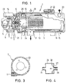
- a vehicle heating device 1 has a burner 2 and a main assembly Heat exchanger 3, which are connected to each other on a common flange part 4.
- an electric motor 5 is arranged, which is a blower 6 for the promotion of Drives combustion air.
- a mixing device 7 is located on the suction side of the blower 6 intended. On the one hand, this is connected to a combustion air supply 8, which is in a Outside wall of a housing part 9 is provided, which the electric motor 5 and the Mixing device 7 surrounds.
- the mixing device 7 formed as a flat cylindrical part, the outer wall of several radially confluent combustion air inlet openings 10 is broken, which within the Housing part 9 are connected to the combustion air supply 8.
- the mixing device 7 is on the other hand provided with a tangentially opening fuel gas inlet opening 11. Combustion air inlet openings 10 and combustion gas inlet opening 11 thus form a right one Angle to each other, which ensures particularly good mixing.
- the fuel gas inlet opening 11 is upstream via a vacuum valve 25, which is also known as Vacuum switch can be formed with a fuel gas supply line 26 in Connection.
- a vacuum valve 25 which is also known as Vacuum switch can be formed with a fuel gas supply line 26 in Connection.
- a diffuser 12 On the pressure side of the blower 6 is followed by a diffuser 12, which for a additional swirling of the fuel gas / combustion air mixture provides. This follows a nozzle-like narrowing central opening in the flange part 4, which in a Combustion chamber 13 merges.
- an ignition electrode 15 is parallel to the External wall of the bored combustion chamber 13 is provided, which has a Ignition spark generator 14 arranged on the outside of the housing part 9 with corresponding electrical Energy is supplied.
- the fuel gases leave the combustion chamber 13 at the flange part 4 opposite End face where it is deflected and via a flue gas duct 16 and an exhaust pipe 17 be discharged from the vehicle heater 1.
- a flue gas duct 16 and an exhaust pipe 17 be discharged from the vehicle heater 1.
- the Heat exchanger 3 supplied via a water inlet 18 water, the one Flue gas duct 16 flows in a spiral surrounding water jacket 19 in countercurrent and leaves the vehicle heater 1 at a water outlet 20.
- the schematically shown vacuum valve 25 has a chamber into which one side opens the fuel gas supply line 26 and the other end with the Fuel gas inlet opening 11 is in flow connection.
- a membrane 27 depending on the prevailing in the chamber Pressure conditions according to the arrows shown in Fig. 4 either to the right creates the confluence of the fuel gas supply line 26 and blocks or at correspondingly strong suction pressure generated by the fan 6 to the left of this opening moves away and thereby the supply of fuel gas to the fuel gas inlet opening 11 enables.
- the fuel gas in the Fuel gas supply line 26 is provided with a slight positive pressure, in which case the Membrane 27 has a low resilient bias, which it lacks Suction pressure through the fan 6 for blocking the fuel gas supply line 26 at the other Merges into a confluence.
- the resilient bias of the membrane 27 is then designed that it is overcome by the building up suction pressure 6 with increasing fan speed and leads to an increasing lifting of the membrane 27.
- the supply of the fuel gas which is controlled by the suction pressure of the blower 6, enables on the one hand a simple structure of a vehicle heater.
- the suction side supply of the fuel gas preferably under a vacuum, the subsequent mixing of which in the Mixing device 7, and the subsequent chopping by the fan 6 and additional swirling of the mixture in the diffuser 12 ensures excellent Preparation of the fuel gas / combustion air mixture, which leads to excellent calorific values.
- a heat shield 29 arranged between the combustion chamber 13 and the mixing device 7 protects the latter from harmful heat radiation from the combustion chamber and thereby enables despite the compact, integrated arrangement of the mixing device 7 in Vehicle heater 1 a reliable mixture preparation free of larger Temperature fluctuations.
Landscapes
- Physics & Mathematics (AREA)
- Thermal Sciences (AREA)
- Engineering & Computer Science (AREA)
- Mechanical Engineering (AREA)
- Air-Conditioning For Vehicles (AREA)
- Wick-Type Burners And Burners With Porous Materials (AREA)
Description
- Fig. 1
- ein Längsschnitt durch ein Fahrzeugheizgerät
- Fig. 2
- einen vergrößerten Längsschnitt durch einen Brenner,
- Fig. 3
- einen Schnitt durch die Mischeinrichtung und
- Fig. 4
- eine schematische Darstellung eines Unterdruckventils bzw. - Schalters.
- 1
- Fahrzeugheizgerät
- 2
- Brenner
- 3
- Wärmetauscher
- 4
- Flanschteil
- 5
- Elektromotor
- 6
- Gebläse
- 7
- Mischeinrichtung
- 8
- Brennluftzufuhr
- 9
- Gehäuseteil
- 10
- Brennlufteintrittsöffnungen
- 11
- Brenngaseintrittsöffnung
- 12
- Leitapparat
- 13
- Brennkammer
- 14
- Zündfunkengeber
- 15
- Zündelektrode
- 16
- Rauchgaskanal
- 17
- Abgasstutzen
- 18
- Wassereintritt
- 19
- Wassermantel
- 20
- Wasseraustritt
- 21
- Überhitzungssicherung
- 22
- Thermostat
- 23
- Steuergerät
- 24
- Flammwächter
- 25
- Unterdruckventil
- 26
- Brenngaszufuhrleitung
- 27
- Membran
- 28
- Halter
- 29
- Hitzeschild
Claims (7)
- Fahrzeugheizgerät (1) mit einem Brenner (2), dem Brennluft über Brennlufteintrittsöffnungen (10) mittels eines Gebläses (6) und dem ferner Brenngas über eine Brenngaszufuhrleitung (26) zugeführt wird, wobei Brennluft und Brenngas auf der Saugseite des Gebläses (6) eintreten, wobei der Eintritt von Brenngas mittels eines vom Differenzdruck des Gebläses (6) gesteuerten Ventils oder Schalters (25) gesteuert wird, dadurch gekennzeichnet, daß das Brenngas in der Brenngaszuführleitung (26) einen Unterdruck gegenüber dem Atmosphärendruck aufweist und das Ventil oder der Schalter (25) unmittelbar an der Brenngaszufuhrleitung (26) anliegt.
- Fahrzeugheizgerät nach Anspruch 1, dadurch gekennzeichnet, daß das Ventil oder der Schalter (25) mittels einer Membran (27) betätigt wird, die bei Stillstand des Gebläses (6) oder langsamer Drehzahl ein Verschließen der Brenngaszufuhrleitung (26) bewirkt.
- Fahrzeugheizgerät nach Anspruch 2, dadurch gekennzeichnet, daß der Unterdruck in der Brenngaszuführleitung (26) ein Δp von etwa 10 bis 20 Pa beträgt.
- Fahrzeugheizgerät nach einem der vorhergehenden Ansprüche, dadurch gekennzeichnet, daß eine stromab der Brenngaszufuhrleitung (26) angeordnete Brenngaseintrittsöffnung (11) und die Brennlufteintrittsöffnungen (10) an einer gemeinsamen Mischeinrichtung (7) unter einem Winkel zueinander einmünden.
- Fahrzeugheizgerät nach Anspruch 4, dadurch gekennzeichnet, daß die Brennlufteintrittsöffnungen (10) als radiale Bohrungen in die Mischeinrichtung (7) einmünden, während die Brenngaseintrittsöffnung (11) als tangentiale Bohrung ausgebildet ist.
- Fahrzeugheizgerät nach Anspruch 4 oder 5, dadurch gekennzeichnet, daß zwischen dem Gebläse (6) und der Brennkammer (13) ein Leitapparat (12) zur Verwirbelung des Brenngas/Brennluftgemisches angeordnet ist.
- Fahrzeugheizgerät nach einem der Ansprüche 4 bis 6, dadurch gekennzeichnet, daß zwischen der Mischeinrichtung (7) und einer Brennkammer (13) ein Hitzeschild (29) angeordnet ist.
Applications Claiming Priority (2)
| Application Number | Priority Date | Filing Date | Title |
|---|---|---|---|
| DE19538947 | 1995-10-19 | ||
| DE19538947A DE19538947C2 (de) | 1995-10-19 | 1995-10-19 | Fahrzeugheizgerät |
Publications (3)
| Publication Number | Publication Date |
|---|---|
| EP0769399A2 EP0769399A2 (de) | 1997-04-23 |
| EP0769399A3 EP0769399A3 (de) | 1998-12-23 |
| EP0769399B1 true EP0769399B1 (de) | 2000-11-02 |
Family
ID=7775270
Family Applications (1)
| Application Number | Title | Priority Date | Filing Date |
|---|---|---|---|
| EP96115780A Expired - Lifetime EP0769399B1 (de) | 1995-10-19 | 1996-10-02 | Fahrzeugheizgerät |
Country Status (4)
| Country | Link |
|---|---|
| US (1) | US5738506A (de) |
| EP (1) | EP0769399B1 (de) |
| CA (1) | CA2188116C (de) |
| DE (2) | DE19538947C2 (de) |
Families Citing this family (18)
| Publication number | Priority date | Publication date | Assignee | Title |
|---|---|---|---|---|
| JP3773152B2 (ja) * | 1997-12-09 | 2006-05-10 | 株式会社ミクニアデック | 車両用蒸発燃焼式ヒータ |
| DE10109412B4 (de) * | 2001-02-27 | 2007-06-28 | J. Eberspächer GmbH & Co. KG | Verfahren zum Charakterisieren des Flammzustandes in einem Heizbrenner eines Fahrzeugheizgerätes |
| JP4571762B2 (ja) * | 2001-07-13 | 2010-10-27 | 株式会社リコー | サーディップ型固体撮像素子 |
| US6674198B2 (en) * | 2002-01-04 | 2004-01-06 | Siemens Vdo Automotive Inc. | Electric motor with integrated heat shield |
| DE10227626A1 (de) * | 2002-06-20 | 2004-01-15 | J. Eberspächer GmbH & Co. KG | Heizeinrichtung, insbesondere für ein Fahrzeug |
| US6772722B2 (en) | 2002-07-15 | 2004-08-10 | Teleflex Canada Limited Partnership | Heater and burner head assembly and control module therefor |
| US7270098B2 (en) * | 2002-07-15 | 2007-09-18 | Teleflex Canada Inc. | Vehicle heater and controls therefor |
| US20050178344A1 (en) * | 2004-02-17 | 2005-08-18 | Garrett Michael K. | Gas delivery system with pre-mix blower |
| DE102005053514A1 (de) * | 2004-11-26 | 2006-07-06 | Webasto Ag | Luftheizgerät für ein Kraftfahrzeug |
| ITPD20070388A1 (it) * | 2007-11-19 | 2009-05-20 | Sit La Precisa S P A Con Socio | Bruciatore, in particolare bruciatore a gas con pre-miscelazione |
| DE102011079018A1 (de) * | 2011-07-12 | 2013-01-17 | J. Eberspächer GmbH & Co. KG | Fahrzeugheizgerät |
| DE102012220792A1 (de) * | 2012-11-14 | 2014-05-15 | Eberspächer Climate Control Systems GmbH & Co. KG | Wärmetauscheranordnung, insbesondere für ein Fahrzeugheizgerät |
| US9296275B2 (en) * | 2013-01-04 | 2016-03-29 | Denso International America, Inc. | Multi-function infrared heating device |
| DE102016107207B4 (de) * | 2016-03-17 | 2020-07-09 | Eberspächer Climate Control Systems GmbH & Co. KG | Brennstoffgasbetriebenes Fahrzeugheizgerät |
| DE102016112887A1 (de) * | 2016-07-13 | 2018-01-18 | Truma Gerätetechnik GmbH & Co. KG | Heizvorrichtung und Verfahren zum Betreiben einer Heizvorrichtung |
| DE102017119077A1 (de) * | 2017-08-21 | 2019-02-21 | Eberspächer Climate Control Systems GmbH & Co. KG | Fahrzeugheizgerät |
| DE102017125783B4 (de) * | 2017-11-06 | 2019-09-05 | Eberspächer Climate Control Systems GmbH & Co. KG | Fahrzeugheizgerät |
| DE102018120030A1 (de) * | 2018-08-17 | 2020-02-20 | Eberspächer Climate Control Systems GmbH & Co. KG | Fahrzeugheizgerät |
Family Cites Families (6)
| Publication number | Priority date | Publication date | Assignee | Title |
|---|---|---|---|---|
| DE2336683A1 (de) * | 1973-07-19 | 1975-02-06 | Junkers & Co | Gasbeheizter wassererhitzer |
| DE3604314A1 (de) * | 1986-02-12 | 1987-08-13 | Webasto Werk Baier Kg W | Heizgeraet, insbesondere zusatzheizgeraet |
| DE3911268A1 (de) * | 1989-04-07 | 1990-10-11 | Honeywell Bv | Regeleinrichtung fuer gasbrenner |
| DE4109841C2 (de) * | 1991-03-26 | 1994-06-09 | Bosch Gmbh Robert | Regelvorrichtung für Gasbrenner mit einem Gebläse zum Zuführen von Verbrennungsluft |
| DE4317981A1 (de) * | 1993-05-28 | 1994-12-01 | Ranco Inc | Gas-Luft-Verhältnisregelvorrichtung für einen Temperaturregelkreis für Gasverbrauchseinrichtungen |
| JPH0886411A (ja) * | 1994-09-19 | 1996-04-02 | Nippon Soken Inc | 燃焼式ヒータ |
-
1995
- 1995-10-19 DE DE19538947A patent/DE19538947C2/de not_active Expired - Fee Related
-
1996
- 1996-10-02 EP EP96115780A patent/EP0769399B1/de not_active Expired - Lifetime
- 1996-10-02 DE DE59606085T patent/DE59606085D1/de not_active Expired - Lifetime
- 1996-10-17 CA CA002188116A patent/CA2188116C/en not_active Expired - Lifetime
- 1996-10-21 US US08/734,168 patent/US5738506A/en not_active Expired - Lifetime
Also Published As
| Publication number | Publication date |
|---|---|
| EP0769399A3 (de) | 1998-12-23 |
| DE19538947C2 (de) | 1998-11-26 |
| CA2188116C (en) | 2000-12-26 |
| EP0769399A2 (de) | 1997-04-23 |
| US5738506A (en) | 1998-04-14 |
| DE19538947A1 (de) | 1997-04-24 |
| CA2188116A1 (en) | 1997-04-20 |
| DE59606085D1 (de) | 2000-12-07 |
Similar Documents
| Publication | Publication Date | Title |
|---|---|---|
| DE19538947C2 (de) | Fahrzeugheizgerät | |
| DE3734197C2 (de) | ||
| DE3209904C2 (de) | Ringkanalgebläse | |
| DE2545234C2 (de) | Mischeinrichtung für Brenner | |
| DE807450C (de) | Brennstoff-Verdampfer fuer Gasturbinen-Brennkammern | |
| DE4319213A1 (de) | Brenner zur schnellen und motorunabhängigen Aufheizung eines Abgaskatalysators | |
| DE2652522C2 (de) | Heizkessel | |
| DE69717880T2 (de) | Energieerzeuger zur Produktion eines heissen Fluidums | |
| DE2660903C2 (de) | Abfackelvorrichtung | |
| DE3882505T2 (de) | Verbrennungsverfahren mit schneller Auslösung und Mittel zu dessen Durchführung in einer Heiz- und Verbrennungsvorrichtung. | |
| EP0309723B1 (de) | Zündbrenner in einer Vorrichtung zum Verbrennen von Festkörperpartikeln im Abgas von Brennkraftmaschinen | |
| DE102010052268B4 (de) | Pulsstrahl-Dampferzeuger | |
| DE2821932C2 (de) | ||
| DE1576756A1 (de) | Abgas-Behandlungsvorrichtung | |
| DE1476475C3 (de) | Vorrichtung zum Nachbrennen von Abgasen | |
| CH441867A (de) | Katalysatorfreie Abgas-Nachbrennvorrichtung | |
| DE10000406A1 (de) | Heizeinrichtung | |
| CH615494A5 (de) | ||
| DE4130376A1 (de) | Vorrichtung zum entfernen von partikeln aus dieselmotorenabgas | |
| DE4326372C2 (de) | Abgasreinigungsvorrichtung für einen Verbrennungsmotor | |
| DE19504180C2 (de) | Heizgerät für insbesondere Fahrzeuge | |
| EP1241408B1 (de) | Brenner für ein Brennstoffgemisch aus Luft und Gas | |
| DE102014003390A1 (de) | Antriebseinrichtung | |
| EP0007424A1 (de) | Brenneranordnung zur Verbrennung flüssiger Brennstoffe | |
| DE3808227A1 (de) | Heizeinrichtung |
Legal Events
| Date | Code | Title | Description |
|---|---|---|---|
| PUAI | Public reference made under article 153(3) epc to a published international application that has entered the european phase |
Free format text: ORIGINAL CODE: 0009012 |
|
| AK | Designated contracting states |
Kind code of ref document: A2 Designated state(s): DE FR GB SE |
|
| PUAL | Search report despatched |
Free format text: ORIGINAL CODE: 0009013 |
|
| AK | Designated contracting states |
Kind code of ref document: A3 Designated state(s): DE FR GB SE |
|
| 17P | Request for examination filed |
Effective date: 19981128 |
|
| GRAG | Despatch of communication of intention to grant |
Free format text: ORIGINAL CODE: EPIDOS AGRA |
|
| GRAG | Despatch of communication of intention to grant |
Free format text: ORIGINAL CODE: EPIDOS AGRA |
|
| GRAH | Despatch of communication of intention to grant a patent |
Free format text: ORIGINAL CODE: EPIDOS IGRA |
|
| 17Q | First examination report despatched |
Effective date: 19990819 |
|
| GRAH | Despatch of communication of intention to grant a patent |
Free format text: ORIGINAL CODE: EPIDOS IGRA |
|
| GRAA | (expected) grant |
Free format text: ORIGINAL CODE: 0009210 |
|
| AK | Designated contracting states |
Kind code of ref document: B1 Designated state(s): DE FR GB SE |
|
| REF | Corresponds to: |
Ref document number: 59606085 Country of ref document: DE Date of ref document: 20001207 |
|
| GBT | Gb: translation of ep patent filed (gb section 77(6)(a)/1977) |
Effective date: 20001116 |
|
| ET | Fr: translation filed | ||
| PLBE | No opposition filed within time limit |
Free format text: ORIGINAL CODE: 0009261 |
|
| STAA | Information on the status of an ep patent application or granted ep patent |
Free format text: STATUS: NO OPPOSITION FILED WITHIN TIME LIMIT |
|
| 26N | No opposition filed | ||
| REG | Reference to a national code |
Ref country code: GB Ref legal event code: IF02 |
|
| REG | Reference to a national code |
Ref country code: GB Ref legal event code: 732E |
|
| REG | Reference to a national code |
Ref country code: GB Ref legal event code: 732E |
|
| REG | Reference to a national code |
Ref country code: FR Ref legal event code: TP |
|
| PGFP | Annual fee paid to national office [announced via postgrant information from national office to epo] |
Ref country code: GB Payment date: 20101021 Year of fee payment: 15 |
|
| GBPC | Gb: european patent ceased through non-payment of renewal fee |
Effective date: 20121002 |
|
| PG25 | Lapsed in a contracting state [announced via postgrant information from national office to epo] |
Ref country code: GB Free format text: LAPSE BECAUSE OF NON-PAYMENT OF DUE FEES Effective date: 20121002 |
|
| PGFP | Annual fee paid to national office [announced via postgrant information from national office to epo] |
Ref country code: FR Payment date: 20141021 Year of fee payment: 19 |
|
| PGFP | Annual fee paid to national office [announced via postgrant information from national office to epo] |
Ref country code: SE Payment date: 20151026 Year of fee payment: 20 |
|
| PGFP | Annual fee paid to national office [announced via postgrant information from national office to epo] |
Ref country code: DE Payment date: 20151223 Year of fee payment: 20 |
|
| REG | Reference to a national code |
Ref country code: FR Ref legal event code: ST Effective date: 20160630 |
|
| PG25 | Lapsed in a contracting state [announced via postgrant information from national office to epo] |
Ref country code: FR Free format text: LAPSE BECAUSE OF NON-PAYMENT OF DUE FEES Effective date: 20151102 |
|
| REG | Reference to a national code |
Ref country code: DE Ref legal event code: R071 Ref document number: 59606085 Country of ref document: DE |
|
| REG | Reference to a national code |
Ref country code: SE Ref legal event code: EUG |