EP0768982B1 - Abgabevorrichtung - Google Patents
Abgabevorrichtung Download PDFInfo
- Publication number
- EP0768982B1 EP0768982B1 EP95928386A EP95928386A EP0768982B1 EP 0768982 B1 EP0768982 B1 EP 0768982B1 EP 95928386 A EP95928386 A EP 95928386A EP 95928386 A EP95928386 A EP 95928386A EP 0768982 B1 EP0768982 B1 EP 0768982B1
- Authority
- EP
- European Patent Office
- Prior art keywords
- container
- base
- product
- region
- plunger
- Prior art date
- Legal status (The legal status is an assumption and is not a legal conclusion. Google has not performed a legal analysis and makes no representation as to the accuracy of the status listed.)
- Expired - Lifetime
Links
Images


Classifications
-
- A—HUMAN NECESSITIES
- A23—FOODS OR FOODSTUFFS; TREATMENT THEREOF, NOT COVERED BY OTHER CLASSES
- A23G—COCOA; COCOA PRODUCTS, e.g. CHOCOLATE; SUBSTITUTES FOR COCOA OR COCOA PRODUCTS; CONFECTIONERY; CHEWING GUM; ICE-CREAM; PREPARATION THEREOF
- A23G9/00—Frozen sweets, e.g. ice confectionery, ice-cream; Mixtures therefor
- A23G9/04—Production of frozen sweets, e.g. ice-cream
- A23G9/22—Details, component parts or accessories of apparatus insofar as not peculiar to a single one of the preceding groups
- A23G9/28—Details, component parts or accessories of apparatus insofar as not peculiar to a single one of the preceding groups for portioning or dispensing
- A23G9/281—Details, component parts or accessories of apparatus insofar as not peculiar to a single one of the preceding groups for portioning or dispensing at the discharge end of freezing chambers
- A23G9/283—Details, component parts or accessories of apparatus insofar as not peculiar to a single one of the preceding groups for portioning or dispensing at the discharge end of freezing chambers for filling containers with material
-
- A—HUMAN NECESSITIES
- A23—FOODS OR FOODSTUFFS; TREATMENT THEREOF, NOT COVERED BY OTHER CLASSES
- A23G—COCOA; COCOA PRODUCTS, e.g. CHOCOLATE; SUBSTITUTES FOR COCOA OR COCOA PRODUCTS; CONFECTIONERY; CHEWING GUM; ICE-CREAM; PREPARATION THEREOF
- A23G3/00—Sweetmeats; Confectionery; Marzipan; Coated or filled products
- A23G3/02—Apparatus specially adapted for manufacture or treatment of sweetmeats or confectionery; Accessories therefor
- A23G3/28—Apparatus for decorating sweetmeats or confectionery
-
- A—HUMAN NECESSITIES
- A23—FOODS OR FOODSTUFFS; TREATMENT THEREOF, NOT COVERED BY OTHER CLASSES
- A23G—COCOA; COCOA PRODUCTS, e.g. CHOCOLATE; SUBSTITUTES FOR COCOA OR COCOA PRODUCTS; CONFECTIONERY; CHEWING GUM; ICE-CREAM; PREPARATION THEREOF
- A23G9/00—Frozen sweets, e.g. ice confectionery, ice-cream; Mixtures therefor
- A23G9/04—Production of frozen sweets, e.g. ice-cream
- A23G9/22—Details, component parts or accessories of apparatus insofar as not peculiar to a single one of the preceding groups
- A23G9/28—Details, component parts or accessories of apparatus insofar as not peculiar to a single one of the preceding groups for portioning or dispensing
-
- B—PERFORMING OPERATIONS; TRANSPORTING
- B65—CONVEYING; PACKING; STORING; HANDLING THIN OR FILAMENTARY MATERIAL
- B65D—CONTAINERS FOR STORAGE OR TRANSPORT OF ARTICLES OR MATERIALS, e.g. BAGS, BARRELS, BOTTLES, BOXES, CANS, CARTONS, CRATES, DRUMS, JARS, TANKS, HOPPERS, FORWARDING CONTAINERS; ACCESSORIES, CLOSURES, OR FITTINGS THEREFOR; PACKAGING ELEMENTS; PACKAGES
- B65D83/00—Containers or packages with special means for dispensing contents
- B65D83/0055—Containers or packages provided with a flexible bag or a deformable membrane or diaphragm for expelling the contents
- B65D83/0072—Containers or packages provided with a flexible bag or a deformable membrane or diaphragm for expelling the contents the contents of a flexible bag being expelled by a piston or a movable bottom or partition provided in the container or the package
-
- B—PERFORMING OPERATIONS; TRANSPORTING
- B67—OPENING, CLOSING OR CLEANING BOTTLES, JARS OR SIMILAR CONTAINERS; LIQUID HANDLING
- B67D—DISPENSING, DELIVERING OR TRANSFERRING LIQUIDS, NOT OTHERWISE PROVIDED FOR
- B67D1/00—Apparatus or devices for dispensing beverages on draught
- B67D1/0001—Apparatus or devices for dispensing beverages on draught by squeezing collapsible or flexible storage containers
-
- B—PERFORMING OPERATIONS; TRANSPORTING
- B65—CONVEYING; PACKING; STORING; HANDLING THIN OR FILAMENTARY MATERIAL
- B65D—CONTAINERS FOR STORAGE OR TRANSPORT OF ARTICLES OR MATERIALS, e.g. BAGS, BARRELS, BOTTLES, BOXES, CANS, CARTONS, CRATES, DRUMS, JARS, TANKS, HOPPERS, FORWARDING CONTAINERS; ACCESSORIES, CLOSURES, OR FITTINGS THEREFOR; PACKAGING ELEMENTS; PACKAGES
- B65D85/00—Containers, packaging elements or packages, specially adapted for particular articles or materials
- B65D85/70—Containers, packaging elements or packages, specially adapted for particular articles or materials for materials not otherwise provided for
- B65D85/72—Containers, packaging elements or packages, specially adapted for particular articles or materials for materials not otherwise provided for for edible or potable liquids, semiliquids, or plastic or pasty materials
- B65D85/78—Containers, packaging elements or packages, specially adapted for particular articles or materials for materials not otherwise provided for for edible or potable liquids, semiliquids, or plastic or pasty materials for ice-cream
Definitions
- This invention relates to dispensing apparatus for dispensing a viscous or semi-solid product from a container.
- An object of the invention is to provide dispensing apparatus having a container, especially suitable for food products which is simple, adaptable and hygienic.
- a container for use in a dispensing apparatus in accordance with claim 1.
- the deforming means is a plunger movable in a generally vertical direction, and a seating for the containers, in the operating position, is located vertically below the plunger, the seating being movable about a generally horizontal axis to a non-operating position to one side of the operating position.
- the seating is carried on an arm presented generally horizontally in the operating position and downwardly inclined to the horizontal in the non-operating position.
- the seating and the arm are releasably securable in each of the operating and non-operating positions and the plunger is movable only when the seating is in the operating position.
- the arm may be L-shaped and located in an inverted position, the shorter limb of the arm carrying the seating, and pivot means is located towards the lower end of the longer limb of the arm.
- the arm may have a handle whereby the arm is movable manually between the operating and non-operating positions, and the seating is arranged for the container to be lifted up and out of the seating, the deformable portion of the container being presented upwardly towards the plunger and the outlet being presented downwardly from the arm when the container is located in the seating.
- the apparatus may include an upright frame having towards its upper end a support for the deforming means and its associated drive means, the frame having intermediate its ends the arm and associated seating, and the frame having towards its lower end a base for supporting the frame, the base including a receiver spaced below the seating and giving access to a receptacle for product discharged from the container.
- the frame houses drive means for the deforming means and lighting means, and a housing surrounds the lighting means and has a light transmission region for lighting the housing from within.
- the deforming means may be driven by a compressed gas operated piston and cylinder arrangement, and the apparatus includes a source of compressed gas and gas reservoir for supplying pressurised gas to the piston and cylinder.
- the deforming means includes locating means movable to engage with the container to locate the container in the seating, and pressure generating means which engages with the deformable portion of the container to deform the portion towards the base in discharging product through the container outlet and the locating means and the pressure generating means are relatively movable so that, after the locating means has engaged the container, the pressure generating means moves relative to the locating means to discharge said product.
- the locating means may comprise a locating member slidably mounted relative to the pressure generating means and resiliently urged by spring means towards a locating position, whereby after said member locates with the container the pressure generating means moves against the action of the spring means to deform the deformable portion of the container and the pressure generating means comprises a plunger head which is shaped to correspond with the internal shape of the base of the container.
- the locating member may be powered towards a locating position independently of operation of the pressure generating means.
- the plunger head is generally cylindrical with curvilinear surfaces at its region which engages the deformable portion of the container.
- the seating is a cup-shaped member arranged to receive a correspondingly-shaped base of the container, the seating having a central opening through which the container outlet is directed when the container is placed in the seating, the container being liftable out of the seating after a dispensing action, and the seating being removable from the arm.
- the seating member may be secured permanently on the arm.
- the outer region of the deformable member may include a turned over lip whereby the member is secured to the base pad by the turned over lip engaging with the upper edge of the base when the deformable member and the base are assembled together after the base is filled with product.
- the container parts are conveniently formed of plastics by injection moulding, by thermoforming or by blow moulding or they may be of paper or cardboard which may be coated with plastic.
- the dispensing apparatus may have a manually or power-operated drive means which causes the deforming means in the form of a plunger to be reciprocally movable towards and away from a container in a dispensing operation of the apparatus.
- the drive means may be electrically, hydraulically or gas operated.
- the arm is pivotable between a product discharge position and a container location position by pivoting through about 40-60° from a horizontal discharge position so that the support is presented to a better viewing position to the operative.
- a manually movable lever to which a shaft is attached for rotation therewith, and a linkage carried on the shaft is connected to a rod on one end of which is mounted the plunger.
- the plunger is movable along and guided by a cylinder arranged vertically and above a container locating position.
- a storage compartment for containers with, if required, refrigeration means for maintaining the containers at the desired dispensing temperature.
- a central deformable region is connected to the outer region through an integral flexible folded portion.
- the folded portion may have downwardly and upwardly directed folds one of which lies closely adjacent an inner surface of the base part when assembled therewith and the junction between the downward and upward folds preferably lying half way down the base part when assembled.
- the central region includes a generally planar portion and the base part is of generally circular section.
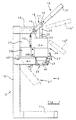
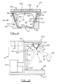
- dispensing apparatus for a dispensing system is manually operated and includes a vertically arranged frame 10 having a base 11 on which may be supported a receptacle (not shown) for product.
- the frame 10 includes upwardly extending frame members 12 at the uppermost end of which are mounted horizontal support arms 13. Between the arms 13 is rotatably mounted a shaft 14 on one end of which is carried for rotation therewith a lever 15.
- the lever 15 is movable between an upper inoperative position 15' through an intermediate position 15'' and a lower position 15'''.
- a linkage assembly 17 including a pair of links 18 rotatably carried on the shaft 14. At the opposite ends of the links 18 is carried a spindle 19, the links 18 being pivotable relative to the spindle 19, and a further pair of links 20 depend from and are pivotally mounted on the spindle 19.
- linkage shown other arrangements can be used such as a double cantilever arrangement, so that downward pressure on the plunger 36 is always in the vertical direction.
- the further links 20 are interconnected at their lower ends by a spindle 22 which extends through the upper end of a rod 23 which is the operating rod of a plunger assembly 24 (shown in more detail in Fig. 3).
- the spindle 22 is rotatably mounted in a bore 25 in the rod 23.
- the plunger assembly 24 includes a cylinder 26 which is mounted on the frame 10 by vertically arranged plates 27 attached at their upper ends to the beam 13 and towards their lower ends to brackets 28 secured to the uprights 12.
- the brackets 28 and plates 27 are interconnected and together provide a support for the cylinder 26.
- the cylinder 26 is open ended and receives coaxially the rod 23.
- the rod 23 carries fixed thereto an upper annular member 29 which fits within and for movement along the inner walls of the cylinder 26.
- a generally cup-shaped member 30 Spaced downwardly from the annular member 29 and along the rod 23, and axially movable relative to the rod 23, is a generally cup-shaped member 30 comprising a further annular member 31 secured to a locating member 32 extending downwardly from the member 31 and defining an inner cylindrical bore 33.
- Towards the lower end of the member 32 is an annular tapered locating portion 34 which is spaced from the inner walls of the cylinder 26.
- an engagement member or plunger head 36 Carried at the lower end of the rod 23 is an engagement member or plunger head 36 secured for movement with the rod 23 along the cylinder 33.
- the lower end of the plunger 36 is formed with a flat surface 37 bounded by a curved periphery 38.
- a spring 40 Engaging between the annular member 29 and the member 31 is a spring 40 which urges the member 31 in a direction away from the annular member 29 but is compressible to the position shown in Figs. 4 and 5 so that the annular member 29 can move close to the member 31 during a dispensing operation.
- the frame 10 also carries intermediate its ends a pivotable arm 41 which is located for pivoting on the uprights 12 about horizontal pivots 42.
- the arm 41 can pivot downwardly from the horizontal position shown in Fig. 1 to a downwardly inclined position 41' which is at an angle of some 50° to the horizontal position.
- a support or seating member 43 for receiving a container 50 of product to be dispensed.
- the seating 43 defines a cup-shaped inner surface 44 in which containers 50, such as shown in Figs. 7-13, can be received.
- a central outlet opening 45 At the lower end of the cup surface 44 is formed a central outlet opening 45 through which product is to be discharged from containers 50.
- the arm 41 is retained in its upper horizontal position by a securing element 47 which engages over the end of the arm and over the brackets 28 but it will be appreciated that other securing means whereby the arm 41 may be released from a securing position, may be employed.
- the arm Upon release of the securing element 47 the arm is movable downwards about pivots 42 to the inclined position 41' which is the position in which containers are placed in and lifted out of the receiving member 43.
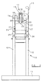
- Fig.6 a pneumatically operated dispensing machine is shown which utilises the same containers 50 as the previously described machine.
- similar reference numbers are given to parts equivalent to those of the machine of Figs. 1-5.
- the machine of Fig. 6 comprises a base 11' and an upwardly extending frame 10'.
- a tray 80 which is located spaced beneath the container dispensing position and extending upwards from the tray 80 is a main frame member 12' located generally centrally of the machine.
- a pivot 42'on which is pivotally supported an inverted L-shaped arm 41' having a longer upwardly directed limb 81 and a shorter outwardly directed limb 82.
- a handle portion 83 by which the arm 41' is moved manually between the upright position shown in full lines in Fig. 6 and the inclined inoperative position, shown by chain lines.
- the arm 41' In the inoperative position the arm is presented to the user for the removal by lifting out, of empty containers from a seating 43', and for the location of full containers 50 in the seating 43'. Movement between the two positions is, in the illustrated embodiment, by moving the arm 41' using the handle 83.
- the arm 41' carries a pair of arcuate support members 84 which extend through slots in the frame 12' and locate the arm 41' in the operative and inoperative position by engagement with the machine frame 10 and by the use of catches to hold the arm 41' in the required position.
- a magnetically or pneumatically operated catch is used when the arm is in the operative position and the support members 84 may have stops for location in the inoperative position.
- a positive locking pin 85 moved by a pneumatic cylinder between a release and a locking position in which the arm 41' is locked, the pin engaging in a recess in the arm 41 in the locking position.
- a position detector 85' is also provided to detect when the arm 41' is in the operation position.
- the outwardly directed portion 82 of the arm 41' is provided with a seating 43' in which containers 50 are located, the seating being shaped to receive the containers 50 and the seating 43' being removable from the portion 82 for cleaning purposes, if required.
- a seating 43' Centrally and in the base of the seating is provided an outlet opening 45' for permitting passage of the product in the container 50 from the container outlet 57 through said opening.
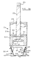
- a plunger 36' Located above and axially aligned with the seating 43' is a plunger 36' forming part of a plunger assembly 24'.
- the plunger 36' is generally cylindrical having a lower flat portion merging through curvilinear portions with the body of the plunger, as in the previous embodiment.
- the plunger 36' is carried on a rod 86 and slidable along the rod 86 is an annular disc 87 which is spring urged by a spring 88 towards the upper end of the plunger 36'.
- the annular disc 87 is moveable relative to the plunger 36' along the rod 86.
- the rod 86 is mounted at its upper end on a piston rod 89 and piston 90 located within a pneumatic cylinder 81.
- the piston 90 and the rod 89 are moved up and down by the introduction of pressure air into the cylinder 91 to cause the plunger 36' to be moved vertically up and down, such movement being movement for discharge of the product from containers 50.
- Supply of air to the cylinder 91 is from a reservoir 92 of pressure air which is supplied from a motor and compressor 93 carried on the machine.
- Control valves (not shown) control the operation of the piston and cylinder arrangement 89, 90, 91 and there are also provided interlock valves or proximity detectors to ensure that the plunger 36' cannot be moved except when the arm 41' is in the operative position and the arm 41' is locked by pin 85 and when there is a container of product 50 located in the seating 43'.
- Further controls can also be provided for timing the introduction and exhaust of air from the cylinder 91 so that the operator simply initiates the discharge sequence. If required the speed of operation can also be controlled and adjusted manually or automatically by valve means 90' according to the hardness of the product and the ease of extruding the product through the container outlet by control of the air pressure to the cylinder 91.
- the sequence of operation of the machine Fig. 6 is to locate a container of product 50 in the seating 43' when the arm 41' is in the inclined receiving or non-operative position.
- the arm 41' is then moved to its vertical position in which the seating 43' lies directly below the plunger 36' and the plunger is operative, by manual movement of the arm using the handle 83.
- An operative movement of the plunger 36' is initiated automatically or by a switch so that the plunger moves downwardly towards the container 50 and the annular disc 87 engages with the top edge of the container 50 and remains in this position during the continued movement of the plunger 36' against the action of spring 88 to fully discharge the contents of the container through the outlet in the container and through the opening 45' in the seating 43'.
- a receptacle (not shown) for receiving product from the container 50 is located below the container discharge outlet.
- the disc 87 may include a downwardly directed shroud (not shown) to prevent access by the operator to the plunger.
- the Fig. 6 embodiment includes a casing 95 surrounding the components of the machine and there are provided light boxes 96 and 97 towards the front and rear of the machine respectively and lit by light sources 98 and 99.
- the light boxes are transparent or translucent and intended to illuminate advertising material or information for the assistance of the operator applied to the casing.
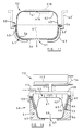
- the container 50 (shown assembled in Fig. 7) for product is formed of two parts, a base part 51 (Fig. 8) and a top, closure or lid part 52 (Fig. 9) which may each be formed of plastics or cardboard.
- the base part 51 has tapered lower and upper side wall portions 53A, 53B between which is a shoulder 53C which walls taper outwards in the upwards direction terminating at the upper edge in a lip 54, the angle of taper being suited to enable base parts 51 to be nested one within the other as shown in Fig.8.
- a suitable angle is some 5° to the vertical or an included angle of 10°.
- a base surface 55 of the base part 51 is generally planar, merging into the side walls 53 through a radiused portion 56.
- an outlet 57 (see particularly Fig. 8A, 8B, 11 and 12) which is formed of weakened radial, star-shaped lines 58 which are capable of being opened up to form an outlet.
- the outlet may be formed under pressure of product in the container or by being formed of a removable part 57A (as shown in Fig.12), removal of which breaks through the weakened portions.
- the outlet 57 is provided by defining a star shape by the weakened or thinned portion 58 of the base 55.
- a removal element 70 in the form of a disc shaped element is attached to the part 57A of the base 55 within the star 58 to be removed by connecting elements 71 whereby when the element 70 is grasped and tilted downwards the central part 57A of the base 55 within the star is detached to provide a star-shaped outlet opening 57 in the base portion 55 through which product is discharged.
- the top part 52 (Fig.9) of the container 50 includes a peripheral lip 60 which is arranged to engage over the lip 54 of the base part 51 to secure the top part 52 to the base part 51 and seal the interior of the container.
- the interfitting of the lip 60 with the lip 54 is, as shown, by a clip action, but it may be by welding, heat sealing or by the parts being a close fit in one another.
- the clip arrangement by which the top part 52 is secured to the base part 51 is shown more clearly in Fig. 10.
- the peripheral lip 60 on the top part 52 is formed with a downwardly directed annular channel 75, the outer internal side of which is formed at 76 with a thickened region.
- the lip 54 on the base part 51 is arranged to fit into the channel 75 and has a thickened region 77 which interfits with the thickened region 76 when the parts 51 and 52 are brought together to hold the top part 52 onto the base part 51.
- the top part 52 has a central deformable region 61 which is generally planar in the form of a disc but which merges through a radius 62 with deformable folded over portions 63 and 64, the lip 60 being formed at the upper edge of the folded over portion 64.
- a portion 65 which, when the top part 52 is assembled to the base part 51 is located half way down the base part 51 and against the shoulder 53C.
- the portion 64 is thickened towards its lower end to provide a shoulder 64A for when top parts are nested together and to prevent the parts locking together.
- the portion 64 is tapered to match the taper of the side wall 53B of the base part.
- At least the regions 61, 62 and 63 of the top part 52 are formed of flexible material so that the top part can deform during dispensing of product from the container 50 and due to engagement of the plunger 36 with the central region 64 of the top part 52.
- the base part 51 is normally stored with a plurality of base parts nested together (Fig. 8). Individual base parts 51 are released from the nested parts and are presented to a product filling machine, which may be of known form, by which the base part 51 is filled with a predetermined amount of product above the level of the shoulder 65 of the part 51 as shown in Fig.8 at F.
- a top part 52 also normally stored nested together (Fig.9), is denested then fitted to the base part 51 until the parts are secured together, in which position the folded over portion 64 lies closely adjacent the inner side wall 53B of the base part, as shown in Fig 7.
- the container containing product may be frozen, transported and stored.
- the product Prior to dispensing of product from the container 50 the product may be tempered to a suitable dispensing temperature in the case of ice cream or other frozen confectionery product or, in some cases, the product within the container may be heated by microwave means.
- a container is located in the seating 43 with the arm 41 in its lowered position 41'.
- the arm 41 is then raised to the horizontal dispensing position and held in place by the securing element 47.
- the lever 15 is in its raised position.
- a proximity detector (not shown) may be provided to detect that a container 50 is in position in the seating before a discharge operation is started.
- the arm 15 is lowered manually which causes, through the linkage 17, the rod 20 to be moved in a downwards direction from the position shown in Fig. 3 towards the position shown in Fig. 4.
- the tapered portions 34 have entered the space between the folded portions 63 and 64 to secure the top part 52 to the base part 51 with the container engaged with the seating 43 with the lip 54 over the top edge 43A of the seating. Only when this securing action has been performed is the plunger 36 engaged with the central region 61 of the top part 52 and the member 32 is prevented from further downward movement.
- the rod 23 continues to move downwards so that the member 32 slides over the rod compressing the spring 40, the surface 37 of the plunger member 36 engages the region 31 and deforms the top part downwardly reducing the internal volume of the container 50 and causing product in the container to be discharged through the outlet 57 as the central region 61 of the top part is deformed towards the base surface 55 of the base part 51.
- the downwardly directed portion 63 of the top part 52 unfolds downwards so that it lies adjacent the inner wall 53A of the base part 51 at 61' (Fig. 7).
- the plunger Upon completion of the movement of the plunger part 36 towards the base 55 of the base part 51 the plunger has adopted the position shown in Fig. 5 and the container is substantially emptied of product.
- the product During discharge of product through the outlet 57 the product is shaped according to the shape of the discharge outlet 57 and the product is discharged into a receptacle below the opening 45 the receptacle being sized to match the capacity of the container.
- the lever 15 is returned to its initial position, the securing means 47 is released from the arm 41 and the empty container, still remaining in the seating 43 by engagement of the locating means 32 with the container 50, is removed therefrom.
- the apparatus is ready for a fresh dispensing operation by location of another container in the seating 43.
- Fig. 3A there is shown an alternative form of locating means 32' in which the tapered lower end is replaced by a generally flat end which in use engages the top outer edge of the assembled container.
- a similar apparatus to that described in Figs. 1-5 can be provided in which the plunger movement is power operated by a piston and cylinder arrangement or powered means, such as is shown in Fig. 6.
- the machine of Fig. 6 is arranged so that this plunger cannot be operated unless the container is in the operating position beneath the plunger. This may be by means of an interlock (not shown) detecting the location of a container in the seating and detecting the position of the arm in the upright position. Further controls may be provided for automatically energising the plunger when the interlocks detect that a dispensing operation can be performed and for returning the plunger to its upper position when the container is fully discharged. The controls can also control the rate of discharge according to the speed of the plunger movement, and whether the stroke of the plunger is interrupted for partial discharge of the container contents. Alternatively container discharge and plunger movement may be manually initiated by suitable switches.
- the air reservoir of the Fig. 6 embodiment enables repeat discharge of product beyond the rate of supply of the air compressor, for rapid repeat operation of the dispenser. Safety interlocks are also provided for avoiding any danger to the operator from the plunger movement.
- the container is supported in the seating 43 during discharge of its contents with the top portion 52 firmly secured to the base part 51 during discharge and substantially the whole of the contents of the container may be discharged therefrom.
- the amount of product within the container can be selected according to requirements to be the size of a predetermined portion of product to be received by a receptacle. Alternatively several portions may be discharged from the same container simply by halting the movement of the discharge plunger 36 in an intermediate position when sufficient product has been discharged.
- the container 50 may be of any suitable size to suit requirements.
- Fig. 13 illustrates an alternative outlet arrangement for the container 50 which is in many respects the same as the previously described container.
- the container is formed with weakened lines 100 radiating from a central position or the lines 100 can be slits or discontinuous breaks in the base of the container. During discharge from the container pressure of product will cause the triangular portions between the lines 100 to be bent outwardly from the centre and permit the product to discharge from the container.
- the container of Fig. 13 may be located within a sealed bag which may contain information concerning the product.
- a container of this kind it would first be necessary to remove the bag from the container before placing it in the seating 43 but it would not be necessary to make any opening in the base of the container.
- the portion 57A may be covered with a removable seal such as a peel off seal or a seal which in itself is opened up by the pressure of product being discharged.
- the container may be of other suitable shapes, for example elliptical, square or rectangular, in the latter forms having radiused corners.
- the container is preferably formed from plastics by thermoforming.
- the container may be formed so that the discharge opening 57 is formed in the part 52, hitherto called the top part or lid.
- the container 50 would be located in the dispensing apparatus in the inverted position and the plunger 36 would engage and deform the parts 55, 56 and 53A of the part 51 into the parts 61, 62 and 63 of the part 52 to discharge product from the opening 57 in the part 52, the opening 57 being formed in the manner described in relation to he illustrated container.
- the modified container would be located and retained in a seating as previously described.
- the side wall 53B of the part 51 and the side wall 64 of the part 52 may have cooperatively shaped profiles so that one is located in the other to secure the parts together, as by contoured indentations or lugs
- the seating surface may terminate short of the portion 56 of the part 51 to further reduce any chance of product being deposited on the seating 43.
- the dispensing apparatus and, in particular, the plunger assembly is, as described, arranged to have a location movement followed by a discharge movement
- the use of a movable support for the container which is lifted up into position towards the plunger assembly may enable the location movement of the plunger assembly to be omitted or modified.
- Location of the container relative to the plunger assembly may be wholly or, in part, achieved when the container is located relative to the plunger assembly.
- the apparatus provides simple and cost effective means for hygienically dispensing the product into any suitable receptacle such as a dish, bowl or an edible receptacle, for example a cone.
- a suitable receptacle such as a dish, bowl or an edible receptacle, for example a cone.
- a wide variety of product can be dispensed by the apparatus depending only on which product is filled into the containers.
- the user can readily locate containers of product on the apparatus because the seating 43 is presented towards the user to readily locate containers in and out of the seating. This is achieved without having to have an unduly long stroke of the rod 20 to afford room for location of containers below the operating plunger.
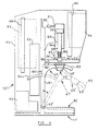
- FIGs. 14 and 15 there is shown the container previously described (see in particular Fig.7) utilised with an alternative form of means for deforming the container to obtain discharge of product therefrom.
- the same reference numbers are used for similar parts to those in previous embodiments.
- a compressed air manifold member 101 defining a chamber 102 communicated with a source of compressed gas through a duct 103.
- a flexible membrane 104 defines the lower side of the chamber 102, the membrane being formed of resilient, flexible material which has a high degree of extensibility.
- the membrane 104 is conveniently formed with radial convolutions to obtain additional extension from the retracted position, the convolutions returning to their initial position after extension.
- annular plate 105 which is engagable with the upper outer rim or lip 60 of the container 50.
- compressed gas is admitted through duct 103 into the chamber 102 whereby to deform the membrane 104 downwards into contact with the lid 52 of the container.
- the portion 61 of the lid is deformed downwards discharging product through the outlet 57 until the portion 61 is deformed into contact with or closely adjacent the inner surface of the base 51 whereupon the container is substantially empty.
- the membrane 104 may be provided with a spring return arrangement (not shown) between the membrane 104 and the housing 101.
- an interlock (not shown) to ensure that gas cannot be admitted to the chamber 102 unless there is a full container 50 in the discharge position in the seating 43.
- the pressure and rate of flow of gas into the chamber 102 is controlled and adjustable according to the rate of discharge of product required, the nature of the product and the size of the container. At a predetermined pressure gas may be admitted for a predetermined period of time which is adjustable.
- a suitable material for the membrane 104 is polyurethane or other material which can resume its initial position without permanent distortion.
- the manifold member 101 can be replaceably mounted on the apparatus to ensure that adequate sealing is retained and for the possibility of cleaning although such manifold would not normally come into contact with the product.
- Fig.15 is shown one way in which the manifold 101 can be mounted in dispensing apparatus, the apparatus being in other respects similar to that shown in Fig.6.
- the manifold member 101 is mounted on a rigid arm 105 on the frame 12 of the apparatus. If desired the manifold member 101 may be vertically moveable into engagement with the container rim 60 after location of the container 50 in the dispensing position.
- a pressurised membrane 104 ensures that pressure is applied to the lid 52 of the container 50 laterally as well as vertically helping to ensure that the lid 52 remains firmly connected to the base 51 and also allowing for the discharge of product which may contain pieces such as fruit and nuts within the product.
- the arrangement takes up little space and is simple in construction.
- Fig. 16 there is shown a further arrangement for deforming the container 50 for obtaining discharge of product therefrom, the same container 50 being shown as in the previous embodiments (as shown in particular in Fig. 7).
- compressed gas is applied directly to the lid 52 of the container by defining a manifold chamber 107 between the lid 52 and a sealing member 108 located above and in sealing contact with the upper lip 60 of the container 50.
- the sealing member 108 is formed with an annular seal 109 of resilient material which is arranged to be urged into sealing engagement with the rim 60.
- the sealing member 108 is of inverted cup shape and is provided with a duct 110 for admitting and discharging compressed gas into and from the chamber 107.
- the sealing member 108 is carried on a piston rod 111 of a piston and cylinder arrangement 112 having a piston 113 and inlet and outlet ducts 114 communicating with a source of compressed gas including a gas reservoir (not shown).
- the container is located in a discharge position in apparatus similar to that of Fig. 15.
- compressed gas is admitted to the piston and cylinder 112 to move the sealing member 108 downwardly with the seal 109 urged into engagement with the lip 60.
- compressed gas is admitted into the chamber 107 through duct 110 to pressurise the lid 52 of the container.
- the deformable portion 61 of the container is deformed downwards towards the base 51 of the container for discharge of product through the outlet 57 in a similar manner to that previously described so that the portion 61 after completion of a discharge movement lies closely adjacent the inner surface of the base 51.
- the air pressure in the chamber 107 is released and the piston 113 is returned to its upper position releasing the sealing member 108 from engagement with the container.
- the seating 43 is then moveable towards a container release position.
- sealing member shown in Fig. 16 other sealing means may be employed, for example a sealing arrangement in which opposed sealing members move towards one another to grip the rim of the container 50 between them prior to pressuring the space above the lid 52 of the container. Again piston and cylinder means may be employed for obtaining relative movement between the sealing members.
- the diameter of the piston and cylinder 112 is relatively large and the stroke of the piston 113 is relatively short to ensure that the force being applied to the container by the seal 109 exceeds the back pressure through entry of air into the chamber 107 and an adequate seal is maintained with the container.
- the use of the pressurised chamber 107 ensures that pressure is applied equally to the lid 52 both vertically and laterally and the lid 52 remains adequately secured to the base 51.
- the duration and pressure of air supplied to the chamber 107 is adjustable and in accordance with the product requirements.
- the sealing member 108 may be removably associated with the rod 111 for ready replacement and/or cleaning.
- FIG. 17 there is shown an alternative form of container 50 for use with any of the embodiments of the apparatus of the invention.
- container 50 for use with any of the embodiments of the apparatus of the invention.
- the same reference numbers are used for similar parts to those in previous embodiments.
- the base 51 of the container 50 is formed of relatively rigid material and in use is located in a suitably shaped seating member 43.
- the base 51 has an outlet 57 which can be in any of the forms previously described but is preferably formed centrally of the base using the arrangement of Fig. 13 having lines of weakness radiating from a central point.
- the outlet 57 is conveniently covered before a discharge operation by a sealing strip (not shown) which may be peeled off or which opens up when discharge takes place.
- the base 51 is of generally circular cross section which is flat over its lower surface 55, has tapered side walls 53 merging with the base 55 through radiused portions 56. At the upper edge of the side wall 53 is formed an out-turned lip 53' arranged to sealingly engage with a corresponding lip 54 of the lid 52.
- the lid 52 is of different form to the previous container embodiments and comprises an inverted cup-shaped deformable portion 61, 62 and 63 which mirrors the shape of the base 51, the portion 63 being generally cylindrical but tapered inwardly towards its upper end.
- the top surface is generally flat and merges with the wall 63 through a radiused portion 62.
- the lid may have a concave depression, as at 61A, prior to assembly with the base, the depression being able to take up a convex shape, as at 61B after filling and assembly.
- the lip 54 is formed at the lower end of the side wall 63 to engage over the lip 53' of the base 51.
- the lips 53 and 54 may be connected to one another in a different manner, such as by heat sealing to ensure that, once assembled, the container parts 51 and 52 are sealingly secured together.
- Filling and discharge of the container of Fig. 17 may be achieved in the manner described in relation to the previous embodiments.
- filling of the container is achieved before assembly of the lid 52 with the base 51 in the manner previously described for the other embodiments of container, product being placed into the base 51 above the upper level of the base in order that the container, when assembled, is substantially filled.
- product may be introduced into the container 50 when the container parts 51 and 52 are assembled by introduction through the opening 57.
- the opening 57 may be formed in the manner of the other containers described but preferably with the arrangement of Fig. 13, with or without a sealing strip.
- the outlet may be formed in the lid 52.
- Discharge of the filled container may be by use of the plunger arrangements shown and described in relation to Figs. 1-5, or Fig. 6.
- discharge may be by the arrangements shown and described in Fig. 14 or Fig. 16.
- the container of Fig. 17 provides a simplified form of container compared with that of the previous embodiments. If required the seating 43 can have upward extensions 43', shown in Fig. 17, according to the arrangement used for deforming the container.
- Fig. 18 there is shown dispensing apparatus incorporating a housing 120 which is arranged to be refrigerated and insulated and to store containers of product for use in the dispensing apparatus shown generally at 122.
- the apparatus for discharging the containers of product may be of any of the forms previously described but the illustrated arrangement 122 is based on the apparatus of Fig. 6 having an arm 41 and operating plunger 36.
- the dispensing apparatus is mounted on the front of the housing 120 on a panel 123 which is conveniently in the form of a door mounted on vertical pivots (not shown) at one side of the door to gain access into the interior of the housing 120.
- a compartment 124 in which is contained an air compressor and reservoir (not shown) or a compressed gas cylinder for powering the dispensing apparatus.
- the housing 120 may be formed with a series of shelves for locating the containers 50 at the desired temperature. Access to the containers may be through the door 123 but, since opening the door 123 will cause the refrigerated compartment formed by the housing 120 to warm up, other arrangement can be made for gaining access to the containers 50. For example a series of drawers of insulating or non-insulating material may be located within the housing 120, the housing itself also being insulated. Thus opening the door 122 to gain access to a drawer does not result in the containers in the other drawers being warmed.
- the compartment 124 may also house refrigeration equipment for the housing 120 and the refrigeration equipment may include a forced air fan for circulating cold air around the housing 120.
- a "cold wall” evaporation system may also be incorporated to avoid the need for regular defrosting. Defrosting can then be part of regular weekly maintenance.
- the housing 120 can be used for tempering or warming up the containers 50 introduced at low temperature to the preferred dispensing temperature of the product.
- the housing may include a heat sink for providing a thermal storage of "cold" to give more rapid cooling for the heat sink when required.
- a fan may be provided to direct air for cooling over the heat sink.
- the housing 120 may be arranged so that the containers descend by gravity from the upper part of the housing towards the lower part as containers are used, there being an entry into the housing 120 at the lower region thereof for removing the containers, such entry being a flap, drawer or similar arrangement.
- the housing arrangement described may be provided independently of the dispensing apparatus.
- housing 120 may be arranged with the compartment 124 at the top of the housing, and coin-freed dispensing of containers 50 from the housing may also be provided.
- other drive means may be used, for example containers of compressed gas (Fig. 6, 14 and 16), or by mechanically operated drive piston (Fig.6)
- the containers described are conveniently sized and the dispensing apparatus arranged to enable a single portion of product to be contained and dispensed from each container.
- Differently sized containers may be provided for serving different sized portions and the same apparatus may be used for differently sized containers by, for example, providing deforming means both in the plunger described which operate covers a variable stroke according to the size of the container thus the containers may be of different lengths.
- deforming means both in the plunger described which operate covers a variable stroke according to the size of the container thus the containers may be of different lengths.
- the arm 41, of the apparatus of Figs. 1-5 and Fig. 6 is movable manually but the arm 41 may be powered in pivoting between the operating or dispensing position and the non-operating or location position.
- there may be a proximity switch which detects the location of a container in the seating 43 to initiate movement of the arm followed by a dispensing action when the container and arm reach the dispensing position.
- the placing of a container in the seating is followed by manual action of a dispensing operation including an arm movement followed by a dispensing movement.
- each embodiment of container the base and the lid are each nestable with other bases and lids respectively.
- Such nestability requires that nesting and denesting be achievable simply, by mechanical means, so that containers can be filled and assembled automatically by such machines.
- shoulders, lugs or other means whereby the lids and bases do not become locked together.
- a concave depression may be formed centrally of the domed portion of the lid as shown in Fig.17.
Claims (5)
- Behälter zur Verwendung in einer Ausgabevorrichtung, umfassend einen Boden (51) zum Aufnehmen eines auszugebenden Produkts, eine Auslassöffnung (57) zur Ausgabe des Produkts, ein verformbares Element (52), das mit dem Boden (51) verbunden ist, einen Bereich (61, 62) des verformbaren Elements (51), der so angeordnet ist, dass er sich beim Eingriff mit Verformungsmitteln (36) der Vorrichtung verformt und in Richtung auf den Boden (51) bewegt wird, um das Produkt aus dem Auslass (57) zu drücken, dadurch gekennzeichnet, dass der Boden einen Übergang zwischen oberen (53B) und unteren Teilen (53A) des Bodens hat, der so angeordnet ist, dass der Bereich (61, 62) des verformbaren Elements (51) sich in den oberen Teil (53B) des Bodens (51) erstreckt, und bei Verformung dieses Bereichs dieser Bereich eintritt in und sich bewegt entlang der inneren Oberflächen des unteren Teils (53A) des Bodens (51), und bei diesem Übergang zwischen den oberen und unteren (53A) Teilen des Bodens befindet sich eine nach außen gerichtete Schulter (53C), wobei das verformbare Element (52) einen Bereich (61, 62) innerhalb des äußeren Teils hat, sodass bei Gebrauch der Bereich (61, 62) mit den Verformungsmitteln (36) in Eingriff kommt und von diesen verformt wird in Richtung des unteren Bereichs (53A) des Bodens (51).
- Behälter nach Anspruch 1, bei welchem der untere Bereich des Bodens (51, 53A) im Wesentlichen zylindrisch mit einem gewölbten Bereich (56) und eine im Wesentlichen flache untere Oberfläche (55) ist, wobei in der unteren Oberfläche der Auslass (57) gebildet ist.
- Behälter nach Anspruch 2, bei welchem der Auslass (57) durch strahlenförmige materialschwache Linien gebildet wird, wobei die materialschwachen Linien (100) den Auslass schaffen, wenn der verformbare Bereich (61, 62) des Behälters bei einem Verformungsvorgang verformt wird.
- Behälter nach einem der Ansprüche 1 - 3, bei welchem der Behälter so angeordnet ist, dass er an seinem Übergang zwischen dem Boden (51) und dem Verschlusselement (52) mit der Schulter (53C) in Eingriff kommt, um den Behälter während der Verformung des verformbaren Bereichs (61, 62) fest zu positionieren, und wobei der Boden (51) so angeordnet wird, dass er auf seiner Außenfläche von einem Trägerelement (43) getragen wird, wobei das Trägerelement in einer Richtung wirkt, die der Wirkung der Verformungsmittel (36) entgegengesetzt ist.
- Behälter nach einem der Ansprüche 1 - 4, bei dem der verformbare Bereich (61, 62) im Wesentlichen gewölbt ist und sich von dem Boden, von dem Übergang (53C) des Bodens (51) und dem Verschlusselement (52) weg erstreckt und über den Bereich des Übergangs in Richtung auf die innere Oberfläche des Bodens verformbar ist.
Priority Applications (2)
| Application Number | Priority Date | Filing Date | Title |
|---|---|---|---|
| EP00124876A EP1095901A1 (de) | 1994-07-02 | 1995-07-03 | Vorrichtung zum Spenden von Nahrungsmitteln |
| EP06014976A EP1710205A3 (de) | 1994-07-02 | 1995-07-03 | Vorrichtung zum Spenden von Nahrungsmitteln |
Applications Claiming Priority (5)
| Application Number | Priority Date | Filing Date | Title |
|---|---|---|---|
| GB9413376 | 1994-07-02 | ||
| GB9413376A GB9413376D0 (en) | 1994-07-02 | 1994-07-02 | Dispensing system |
| GBGB9507242.7A GB9507242D0 (en) | 1995-04-07 | 1995-04-07 | Dispensing system |
| GB9507242 | 1995-04-07 | ||
| PCT/GB1995/001557 WO1996001224A1 (en) | 1994-07-02 | 1995-07-03 | Dispensing apparatus |
Related Child Applications (1)
| Application Number | Title | Priority Date | Filing Date |
|---|---|---|---|
| EP00124876A Division EP1095901A1 (de) | 1994-07-02 | 1995-07-03 | Vorrichtung zum Spenden von Nahrungsmitteln |
Publications (2)
| Publication Number | Publication Date |
|---|---|
| EP0768982A1 EP0768982A1 (de) | 1997-04-23 |
| EP0768982B1 true EP0768982B1 (de) | 2003-03-12 |
Family
ID=26305189
Family Applications (3)
| Application Number | Title | Priority Date | Filing Date |
|---|---|---|---|
| EP95928386A Expired - Lifetime EP0768982B1 (de) | 1994-07-02 | 1995-07-03 | Abgabevorrichtung |
| EP06014976A Withdrawn EP1710205A3 (de) | 1994-07-02 | 1995-07-03 | Vorrichtung zum Spenden von Nahrungsmitteln |
| EP00124876A Withdrawn EP1095901A1 (de) | 1994-07-02 | 1995-07-03 | Vorrichtung zum Spenden von Nahrungsmitteln |
Family Applications After (2)
| Application Number | Title | Priority Date | Filing Date |
|---|---|---|---|
| EP06014976A Withdrawn EP1710205A3 (de) | 1994-07-02 | 1995-07-03 | Vorrichtung zum Spenden von Nahrungsmitteln |
| EP00124876A Withdrawn EP1095901A1 (de) | 1994-07-02 | 1995-07-03 | Vorrichtung zum Spenden von Nahrungsmitteln |
Country Status (8)
| Country | Link |
|---|---|
| US (1) | US5918767A (de) |
| EP (3) | EP0768982B1 (de) |
| JP (3) | JP3840562B2 (de) |
| AT (1) | ATE234260T1 (de) |
| AU (1) | AU2802795A (de) |
| DE (1) | DE69529903T2 (de) |
| ES (1) | ES2192581T3 (de) |
| WO (1) | WO1996001224A1 (de) |
Families Citing this family (82)
| Publication number | Priority date | Publication date | Assignee | Title |
|---|---|---|---|---|
| GB9609182D0 (en) * | 1996-05-02 | 1996-07-03 | Mcgill Tech Ltd | Dispensing container and apparatus |
| US6854875B2 (en) * | 1997-10-29 | 2005-02-15 | Mcgill Technology Limited | Food blending apparatus |
| DE69907009T2 (de) * | 1998-10-20 | 2004-03-11 | Ezee Whip Dispensing Systems Ltd., Milton Keynes | Abgabevorrichtung für abgabe von gefrorenen süssspeisen aus vorgefüllten behältern, und ein abgabesytem mit einer abgabevorrichtung und mehreren behälter |
| CA2251065C (en) * | 1998-10-20 | 2002-06-11 | Andrew Michael Wells | Frozen dessert dispensing system |
| EP0995685B1 (de) * | 1998-10-22 | 2003-04-16 | Whip Dispensing Systems Limited Ezee | Abgabeeinheit für gefrorene Süssspeisen |
| ES2164556B2 (es) * | 1999-09-13 | 2003-05-01 | Unilever Nv | Envase contenedor de helado con dispensado por extrusion y maquina para la dispensacion correspondiente. |
| GB9925014D0 (en) * | 1999-10-23 | 1999-12-22 | Mcgill Tech Ltd | Dispensing apparatus |
| GB0003820D0 (en) | 2000-02-19 | 2000-04-05 | Mcgill Tech Ltd | Dispensing apparatus |
| ES2205953B2 (es) * | 2000-04-12 | 2005-04-16 | Unilever, N.V. | Maquina extrusora de producto helado comestible. |
| US20020119221A1 (en) * | 2000-12-19 | 2002-08-29 | Humiaki Matsukura | Food package and method and device for extrusion of food |
| GB0109940D0 (en) * | 2001-04-23 | 2001-06-13 | Mcgill Tech Ltd | Dispensing means |
| GB0114685D0 (en) | 2001-06-15 | 2001-08-08 | Mcgill Tech Ltd | Dispensing apparatus and method |
| GB0117928D0 (en) * | 2001-07-23 | 2001-09-12 | Mcgill Tech Ltd | Container with outlet |
| KR100403888B1 (ko) * | 2001-07-28 | 2003-11-05 | 김희택 | 아이스크림 분배장치 |
| US20030090958A1 (en) * | 2001-11-15 | 2003-05-15 | Miller Eric R. | Frozen confection dispenser and associated methods |
| DE10158557B4 (de) * | 2001-11-22 | 2008-01-31 | Huhtamaki Alf Zweigniederlassung Der Huhtamaki Deutschland Gmbh & Co. Kg | Kartusche und dazugehöriger Kolben |
| CN100343139C (zh) * | 2002-03-29 | 2007-10-17 | 日诚股份有限公司 | 可塑性食品用分配容器 |
| NL1020492C2 (nl) * | 2002-04-26 | 2003-10-28 | Well Design Associates B V | Samendrukken van houders. |
| JP2005533977A (ja) * | 2002-07-24 | 2005-11-10 | マクギル テクノロジー リミテッド | 駆動機構 |
| IL156940A0 (en) * | 2002-07-30 | 2004-02-08 | Unilever Plc | Portable dispenser for dispensing frozen aerated edible products |
| EP1386542A1 (de) * | 2002-07-30 | 2004-02-04 | Unilever Plc | Tragbare Ausgabevorrichtung zum Spenden von essbaren lufthaltigen gefrorenen Produkten |
| ITMI20022364A1 (it) * | 2002-11-07 | 2004-05-08 | Tgc Srl | Dispositivo per alimentare inchiostro preconfezionato al calamaio di |
| US6820765B2 (en) * | 2003-01-07 | 2004-11-23 | Richard Charles Pahl | Compact countertop freezer and soft-serve method |
| WO2004067386A2 (en) * | 2003-01-31 | 2004-08-12 | Nestec S.A. | Viscous food and beverage dispensing system |
| ES2234452T3 (es) * | 2003-02-18 | 2005-12-01 | Unilever N.V. | Producto aireado congelado. |
| DE20308396U1 (de) * | 2003-05-28 | 2003-07-24 | Nestle Schoeller Gmbh & Co Kg | Abgabevorrichtung für ein Lebensmittel, insbesondere Speiseeis |
| KR100520197B1 (ko) * | 2003-07-08 | 2005-10-11 | 김희택 | 아이스크림 분배기 |
| GB0318584D0 (en) * | 2003-08-07 | 2003-09-10 | Mcgill Tech Ltd | Mixing apparatus |
| EP1586534A1 (de) * | 2004-02-18 | 2005-10-19 | MDS Global Holding Ltd. | Abgabe einer Substanz |
| US20050183426A1 (en) * | 2004-02-24 | 2005-08-25 | Learned Douglas A. | Frozen dessert dispensing machine |
| WO2005100208A1 (ja) * | 2004-04-15 | 2005-10-27 | Satoshi Anzai | 押出式容器 |
| WO2005113387A2 (en) * | 2004-05-14 | 2005-12-01 | Ezee Whip Ice-Cream Limited | A food container, dispensing apparatus and method |
| US7163128B2 (en) * | 2004-05-20 | 2007-01-16 | Savage Don H | Hard ice cream dispenser |
| ITPI20040091A1 (it) * | 2004-12-07 | 2005-03-07 | Marco Bianchi | Distributore per prodotto alimentare caldo |
| JP4395639B2 (ja) * | 2005-03-29 | 2010-01-13 | アイマー・プランニング株式会社 | 印刷機 |
| GB0522465D0 (en) * | 2005-11-03 | 2005-12-14 | Scottish & Newcastle Plc | Method and apparatus for dispensing beverages |
| ITPI20060061A1 (it) * | 2006-06-01 | 2007-12-02 | Marco Bianchi | Distributore per prodotto alimentare caldo |
| SE530703C2 (sv) * | 2006-12-22 | 2008-08-19 | Asept Int Ab | Anordning för utportionering samt utportioneringsorgan till sådan anordning |
| US8083090B2 (en) | 2007-03-22 | 2011-12-27 | Patricia Cocchiarella | Portion control plate cover |
| EP2237707B1 (de) * | 2007-12-21 | 2011-10-19 | MDS Global Holding Ltd. | Substanzausgabesystem |
| EP2266417A1 (de) * | 2009-06-26 | 2010-12-29 | Nestec S.A. | Behälter für eine Vorrichtung zur Herstellung eines gefrorenen Konfekts und Vorrichtung zur Herstellung eines gefrorenen Konfekts |
| GB0916618D0 (en) | 2009-09-22 | 2009-11-04 | Mcgill Tech Ltd | Apparatus for dispensing food product |
| EP2592943B1 (de) | 2010-07-16 | 2014-12-17 | McGill Technology Limited | Spendervorrichtung |
| JP5625682B2 (ja) * | 2010-09-27 | 2014-11-19 | 株式会社柏木モールド | 製氷容器 |
| EP2522227A1 (de) * | 2011-05-11 | 2012-11-14 | Bühler AG | Vorrichtung und Verfahren zur Herstellung eines geformten Verzehrguts |
| DE102011082021A1 (de) | 2011-09-01 | 2013-03-07 | Robert Bosch Gmbh | Verfahren und Vorrichtung zur dreidimensionalen Sichtprüfung eines Bauteils |
| TW201332818A (zh) * | 2011-09-07 | 2013-08-16 | Gojo Ind Inc | 刮刷器泡沫泵,再填充單元,及用於刮刷器泡沫泵之分配器 |
| MX2012005323A (es) * | 2012-05-07 | 2012-08-06 | Ma Del Pilar Zanella Breton | Aplicador dispensador para hielo facial. |
| US9265281B2 (en) * | 2012-05-15 | 2016-02-23 | T.F.H. Publications, Inc. | Pet chew forming apparatus for drug dispensing, methods of forming pet chew products and pet chew products thereof |
| US9597706B2 (en) * | 2013-03-15 | 2017-03-21 | Rooftop Research, Llc | Container and substance dispensing system |
| GB201308810D0 (en) | 2013-05-16 | 2013-07-03 | Mcgill Tech Ltd | Container with outlet |
| CO7170018A1 (es) * | 2013-07-25 | 2015-01-28 | Meals De Colombia S A S | Dispositivo de extrusión y cartucho colapsable que contiene material alimenticio extrudible |
| DE102013109265A1 (de) * | 2013-08-27 | 2015-03-05 | Krones Ag | Vorrichtung und Verfahren zum Entleeren von Behältnissen mit Steuerung eines Antriebsdrehmomentes |
| EP3038948A4 (de) * | 2013-08-30 | 2016-09-28 | Container Innovations LLC | Verformbarer behälter und ausgabemaschine |
| US9801505B2 (en) | 2013-12-20 | 2017-10-31 | Toaster Labs, Inc. | Automatic fluid dispenser |
| US10189038B2 (en) | 2013-12-20 | 2019-01-29 | Toaster Labs, Inc. | Inductively heatable fluid reservoir for various fluid types |
| US10144032B2 (en) | 2013-12-20 | 2018-12-04 | Toaster Labs, Inc. | Inductively heatable fluid reservoir |
| US10098510B2 (en) * | 2013-12-20 | 2018-10-16 | Toaster Loabs, Inc. | Pneumatically driven fluid dispenser |
| US10433372B2 (en) | 2013-12-20 | 2019-10-01 | Toaster Labs, Inc. | Portable fluid warming device |
| US9974416B2 (en) | 2013-12-20 | 2018-05-22 | Toaster Labs, Inc. | Automatic heated fluid dispenser |
| DE102014117278A1 (de) * | 2014-11-25 | 2016-05-25 | Krones Ag | Hubeinheit zum Anheben und Absenken eines Behälters in einer Behälterbehandlungsanlage |
| US10264926B2 (en) * | 2015-02-04 | 2019-04-23 | Gojo Industries, Inc. | Collapsible liquid container, fluid dispenser for collapsible liquid container, and method for making collapsible liquid container |
| US10334868B2 (en) | 2016-06-16 | 2019-07-02 | Sigma Phase, Corp. | System for providing a single serving of a frozen confection |
| US10426180B1 (en) | 2016-06-16 | 2019-10-01 | Sigma Phase, Corp. | System for providing a single serving of a frozen confection |
| US10358284B2 (en) | 2016-06-16 | 2019-07-23 | Sigma Phase, Corp. | System for providing a single serving of a frozen confection |
| US20180118554A1 (en) * | 2016-11-01 | 2018-05-03 | Sone Llc | Apparatus for dispensing viscous liquids from a container |
| US11192674B2 (en) | 2017-03-29 | 2021-12-07 | Mars, Incorporated | Device and method for dispensing product from a flexible package |
| GB201713736D0 (en) * | 2017-08-25 | 2017-10-11 | Mcgill Tech Ltd | Dispensing apparatus |
| KR200490719Y1 (ko) * | 2018-03-21 | 2019-12-20 | 김희택 | 아이스크림 분배용기 |
| US10543978B1 (en) | 2018-08-17 | 2020-01-28 | Sigma Phase, Corp. | Rapidly cooling food and drinks |
| US10612835B2 (en) | 2018-08-17 | 2020-04-07 | Sigma Phase, Corp. | Rapidly cooling food and drinks |
| US11470855B2 (en) | 2018-08-17 | 2022-10-18 | Coldsnap, Corp. | Providing single servings of cooled foods and drinks |
| IT201900003251A1 (it) * | 2019-03-06 | 2020-09-06 | Stefano Vulcano | Distributore automatico di un prodotto alimentare, quale gelato, capsula di contenimento del prodotto alimentare e metodo di funzionamento del distributore |
| US11781808B2 (en) | 2019-04-09 | 2023-10-10 | Coldsnap, Corp. | Brewing and cooling a beverage |
| US11849739B1 (en) | 2019-08-15 | 2023-12-26 | Container Innovations LLC | Collapsible, deformable container and dispensing apparatus |
| EP4072307B1 (de) * | 2019-12-11 | 2023-07-12 | Unilever IP Holdings B.V. | System und verfahren zur ausgabe eines gefrorenen konfekts |
| US11337438B2 (en) | 2020-01-15 | 2022-05-24 | Coldsnap, Corp. | Rapidly cooling food and drinks |
| TW202202790A (zh) | 2020-06-01 | 2022-01-16 | 美商寇德斯納普公司 | 用於快速冷卻食物及飲料的冷凍系統 |
| US11566832B2 (en) * | 2021-01-27 | 2023-01-31 | Ellen Li LIAO | Ice shaver |
| GB2605752B (en) | 2021-01-28 | 2023-09-06 | Mcgill Tech Limited | Dispensing system |
| US11827402B2 (en) | 2021-02-02 | 2023-11-28 | Coldsnap, Corp. | Filling aluminum cans aseptically |
| GB2611311B (en) | 2021-09-29 | 2023-12-06 | Mcgill Tech Limited | Dispensing apparatus |
Family Cites Families (108)
| Publication number | Priority date | Publication date | Assignee | Title |
|---|---|---|---|---|
| CA448571A (en) * | 1948-05-18 | C. Hasselhorn Walter | Bellows construction | |
| US1663677A (en) * | 1921-12-01 | 1928-03-27 | Robert W Byerly | Fire extinguisher and container for fire-extinguishing liquids and other fluids |
| DE521761C (de) * | 1929-12-11 | 1931-03-26 | Willi Schlichenmaier | Vorrichtung zum Aufbringen von Verzierungen auf Kuchen, Torten u. dgl. |
| US2120640A (en) * | 1935-04-20 | 1938-06-14 | Richard A Craemer | Dispensing congealed foodstuffs |
| US2242407A (en) * | 1939-10-19 | 1941-05-20 | Westinghouse Electric & Mfg Co | Refrigeration apparatus |
| US2401417A (en) * | 1940-12-26 | 1946-06-04 | Edgar S Engle | Dispensing system |
| US2408704A (en) * | 1944-05-04 | 1946-10-01 | George R Taylor | Liquid cooler for refrigerators |
| US2559840A (en) * | 1946-04-06 | 1951-07-10 | Robert L Arthur | Ice cream dispenser |
| GB653136A (en) * | 1948-08-25 | 1951-05-09 | Henry George William Hosking | Improvements in or relating to containers for dispensing materials |
| US2558887A (en) * | 1948-11-01 | 1951-07-03 | Thomas R Tesiero | Ice-cream dispenser |
| US2631761A (en) * | 1950-07-11 | 1953-03-17 | Sam R Gates | Follower type ice-cream dispensing machine |
| US2752068A (en) * | 1952-05-03 | 1956-06-26 | Dairymat Corp | Liquid dispensing devices |
| US2889949A (en) * | 1956-11-29 | 1959-06-09 | Nirenberg Morris | Ice cream dispensing apparatus |
| FR1168470A (fr) * | 1957-01-21 | 1958-12-09 | Moteur à combustion interne à deux ou quatre temps sans frottement et sans fuite | |
| FR1219079A (fr) * | 1959-03-21 | 1960-05-16 | Andre Del Pozo Ets | Procédé de fabrication d'objet en matière plastique et objets conformes à ceux obtenus par ce procédé |
| CH372974A (de) * | 1959-09-26 | 1963-10-31 | Schmidt Warren | Ausdrückbarer Behälter für Flüssigkeiten und pastenförmige Massen |
| US3157314A (en) * | 1961-01-12 | 1964-11-17 | Nadler Emanuel | Refillable dispenser with flexible outer casing |
| US3104031A (en) * | 1961-01-26 | 1963-09-17 | Milan F Wagner | Dispenser with a cartridge having a paste composition therein |
| US3081920A (en) * | 1961-03-27 | 1963-03-19 | Phelan Louis A M | Serving valve for continuous freezers |
| US3155281A (en) * | 1962-04-09 | 1964-11-03 | Questron America Inc | Container |
| US3178061A (en) * | 1963-12-18 | 1965-04-13 | Joseph J Giacalone | Refrigerator door canteen |
| US3349973A (en) * | 1964-02-04 | 1967-10-31 | Chemetron Corp | Receptacle filling machines |
| US3250433A (en) * | 1964-08-21 | 1966-05-10 | Allen Electronics Inc | Liquid dispensing unit |
| US3330129A (en) * | 1965-08-02 | 1967-07-11 | Sweden Freezer Mfg Co | Dispensing freezer with flavor selection |
| US3288333A (en) * | 1965-09-21 | 1966-11-29 | Jr John Valk | Caulking gun cartridtge |
| US3371822A (en) * | 1966-07-01 | 1968-03-05 | Galloway Co | Bulk delivery, storage and dispensing apparatus for liquid ice cream mixes and the like |
| US3413820A (en) * | 1966-09-26 | 1968-12-03 | Glacier Ware Inc | Supreme service assembly |
| US3435996A (en) * | 1967-07-06 | 1969-04-01 | United Aircraft Corp | Positive expulsion device |
| GB1300386A (en) * | 1969-02-10 | 1972-12-20 | Metal Box Co Ltd | Improvements in dispensers for flowable products |
| US3677443A (en) * | 1969-07-14 | 1972-07-18 | Dca Food Ind | Apparatus for dispensing frozen comestibles |
| US3826409A (en) * | 1971-06-25 | 1974-07-30 | E Chilcoate | Liquid dosage dispenser |
| US4022031A (en) * | 1973-05-02 | 1977-05-10 | Calim Thomas F | Method for producing frozen confection |
| US4098434A (en) * | 1975-06-20 | 1978-07-04 | Owens-Illinois, Inc. | Fluid product dispenser |
| US4163802A (en) * | 1977-03-04 | 1979-08-07 | Pine State Creamery Company | Preparation of yogurt |
| DE2714611C2 (de) * | 1977-04-01 | 1982-04-08 | M.A.N.- Roland Druckmaschinen AG, 6050 Offenbach | Vorrichtung zum Auspressen von Farbe aus einer über dem Farbkasten einer Druckmaschine angeordneten Farbdose |
| US4169548A (en) * | 1978-03-13 | 1979-10-02 | Liqui-Box Corporation | Flexible dispenser valve |
| US4231492A (en) * | 1978-03-14 | 1980-11-04 | Oatey Co. | Apparatus and method for dispensing putty-like material |
| US4213545A (en) * | 1978-09-20 | 1980-07-22 | Textron, Inc. | Expanding bellows for expulsion tank |
| US4335835A (en) * | 1978-12-26 | 1982-06-22 | Anatros Corporation | Device for the intravenous or enteric infusion of liquids into the human body at a predetermined constant rate |
| JPS55107607A (en) * | 1979-02-13 | 1980-08-18 | Nagano Nobafuoomu Kk | Method of packing mushrooms |
| DE2949368A1 (de) * | 1979-12-07 | 1981-06-11 | Hilti AG, 9494 Schaan | Geraet zum abgeben von ein- oder mehrkomponentenmassen |
| US4340152A (en) * | 1980-08-08 | 1982-07-20 | Baxter Travenol Laboratories, Inc. | Method and apparatus for removing the contents of flexible or collapsible containers |
| US4484697A (en) * | 1980-08-27 | 1984-11-27 | Shasta Beverages, Inc. | Method and apparatus for dispensing liquid |
| US4423829A (en) * | 1980-08-28 | 1984-01-03 | Container Industries Inc. | Apparatus for containing and dispensing fluids under pressure and method of manufacturing same |
| US4452823A (en) * | 1981-01-26 | 1984-06-05 | Landwide Foods, Inc. | Packaged frozen food product |
| US4420948A (en) * | 1981-03-12 | 1983-12-20 | Savage Don H | Apparatus for dispensing hard ice cream and the like |
| US4458830A (en) * | 1981-05-18 | 1984-07-10 | Werding Winfried J | Appliance for discharging a non-compressible liquid, creamy or pasty product under pressure |
| USD268840S (en) | 1981-07-06 | 1983-05-03 | Whirla Whip Marketing Corporation | Frozen comestibles dispenser housing |
| USD272404S (en) | 1981-08-27 | 1984-01-31 | Lancaster Colony Corporation | Casserole |
| USD285082S (en) | 1983-07-25 | 1986-08-12 | International Food Equipment Inc. | Housing for frozen dessert mixer and dispenser |
| US4506988A (en) * | 1983-10-31 | 1985-03-26 | Reed Claude A | Comestible converting apparatus |
| CH658636A5 (fr) * | 1983-11-02 | 1986-11-28 | Serge Michielin | Dispositif d'obturation etanche adaptable a toute forme d'emballage ou appareillage contenant des fluides. |
| US4723688A (en) * | 1983-11-03 | 1988-02-09 | Munoz Edward A | Beverage container and dispenser |
| US4574987A (en) * | 1984-05-01 | 1986-03-11 | General Foods Corporation | Dispenser package for soft-frozen comestibles |
| USRE32379E (en) * | 1984-05-29 | 1987-03-24 | Collapsible bottle | |
| US4492313A (en) * | 1984-05-29 | 1985-01-08 | William Touzani | Collapsible bottle |
| US4775564A (en) * | 1985-03-11 | 1988-10-04 | The Goodyear Tire & Rubber Company | Collapsible-stable blown container |
| IT206816Z2 (it) * | 1985-07-26 | 1987-10-01 | Carpigiani Bruto Mach | Dispositivo a pistone erogatore per macchine per la fabbricazione di gelati |
| US4651538A (en) * | 1985-09-06 | 1987-03-24 | Schneider Metal Manufacturing Co. | Beverage cooler having a cold plate and plastic ice bin |
| US4660740A (en) * | 1986-02-18 | 1987-04-28 | The Sodamaster Company Of America | Gasification of fluids |
| US4711373A (en) * | 1986-04-10 | 1987-12-08 | Trinity Foundation | Portable dispensing system |
| EP0246052A1 (de) * | 1986-05-10 | 1987-11-19 | Cadbury Schweppes Limited | Getränkespender |
| DE3618634A1 (de) * | 1986-06-03 | 1987-12-10 | Jean Pierre Denis | Ausgabevorrichtung fuer getraenke |
| US4722457A (en) * | 1986-09-05 | 1988-02-02 | Fibre Glass-Evercoat Company, Inc. | Dispensing device |
| US4773458A (en) * | 1986-10-08 | 1988-09-27 | William Touzani | Collapsible hollow articles with improved latching and dispensing configurations |
| FR2609450A1 (fr) * | 1987-01-09 | 1988-07-15 | Ludi Jean Claude | Recipient pour liquides pliable, avec auto-blocage en position pliee |
| EP0285709A1 (de) * | 1987-04-06 | 1988-10-12 | BRAVO S.p.A. | Speiseeisspender mit Speiseeispatrone |
| US4796784A (en) * | 1987-07-02 | 1989-01-10 | G & S Metal Product Company, Inc. | Soft ice cream dispenser |
| JPH0831158B2 (ja) * | 1987-07-02 | 1996-03-27 | 株式会社東芝 | 紙葉類の厚さ検知装置 |
| US5215222A (en) * | 1987-12-10 | 1993-06-01 | Mcgill Shane R | Collapsible dispensing container |
| IT1232928B (it) * | 1987-10-28 | 1992-03-10 | Bravo Spa | Distributore di gelato funzionante con una cartuccia di gelato a perdere. |
| GB2213532B (en) * | 1987-12-10 | 1992-01-29 | Shane Robert Mcgill | Dispensing apparatus |
| US4871001A (en) * | 1987-12-31 | 1989-10-03 | House Food Industrial Company, Ltd. | Device for filling viscous material |
| USD307754S (en) | 1988-05-11 | 1990-05-08 | Creative Technologies, Corporation | Ice cream making machine |
| US5060826A (en) * | 1988-08-25 | 1991-10-29 | Fabricated Metals, Inc. | Container with inflatable vessel for controlling flow of liquid or viscous material |
| US4913713A (en) * | 1989-04-04 | 1990-04-03 | Riclar International | Versatile countertop cooler |
| ES1007854Y (es) * | 1988-09-27 | 1989-09-01 | Debarcelona Dissenys, S.A. | Molde-recipiente para la obtencion de pequenos bloques de hielo. |
| US5048724A (en) * | 1988-11-22 | 1991-09-17 | Fedpak Systems, Inc. | Soft serve frozen confection dispenser |
| US5405054A (en) * | 1988-11-22 | 1995-04-11 | Fedpak Systems, Inc. | Frozen confection dispensing apparatus |
| FR2639914B1 (fr) * | 1988-12-05 | 1991-03-22 | Corbiere Jerome | Nouveau dispositif distributeur pour preparations liquides |
| US4938386A (en) * | 1989-01-18 | 1990-07-03 | The Meyer Company | Cup trip assembly |
| US4921147A (en) * | 1989-02-06 | 1990-05-01 | Michel Poirier | Pouring spout |
| US4921135A (en) * | 1989-03-03 | 1990-05-01 | Lawrence Pleet | Pressurized beverage container dispensing system |
| GB8905629D0 (en) * | 1989-03-11 | 1989-04-26 | Mcgill Shane R | Dispensing apparatus |
| FR2649074B1 (fr) * | 1989-06-30 | 1991-10-31 | Agc Design Sarl | Recipient avec flacon a section elastique |
| GB2234556B (en) * | 1989-07-20 | 1993-04-28 | Shane Robert Mcgill | Dispensing apparatus for frozen product |
| IE902575A1 (en) * | 1989-07-20 | 1991-02-27 | Mcgill Shane Robert | Dispensing apparatus for frozen product |
| US5002193A (en) * | 1989-08-15 | 1991-03-26 | Touzani William N | Collapsible hollow articles with latching configuration and attached handle |
| US5188261A (en) * | 1990-01-12 | 1993-02-23 | Inotec Corporation | Collapsible drink dispenser |
| US5027698A (en) * | 1990-02-20 | 1991-07-02 | Munroe Chirnomas | Ice cream vending machine |
| JPH0719274Y2 (ja) * | 1990-10-03 | 1995-05-10 | 日世株式会社 | ソフトクリーム状食品用サーバー |
| US5090963A (en) * | 1990-10-19 | 1992-02-25 | Product Development (Z.G.S.) Ltd. | Electrochemically driven metering medicament dispenser |
| US5100025A (en) * | 1991-03-04 | 1992-03-31 | Mcgraw Kim A | Pump dispensing apparatus |
| GB9104564D0 (en) * | 1991-03-05 | 1991-04-17 | Mcgill Shane R | Container |
| US5265764A (en) * | 1991-08-22 | 1993-11-30 | Ro-Co Manufacturing Co. | Apparatus for pneumatically dispensing a bagged soft frozen product |
| US5269428A (en) * | 1992-01-21 | 1993-12-14 | Gilbert Neil Y | Collapsible container |
| US5333761A (en) * | 1992-03-16 | 1994-08-02 | Ballard Medical Products | Collapsible bottle |
| US5361941A (en) * | 1992-03-24 | 1994-11-08 | Froezert Usa Inc. | Chilled product dispensing system |
| US5463878A (en) * | 1992-11-03 | 1995-11-07 | Froezert Usa, Inc. | Chilled product dispensing apparatus |
| ATE234565T1 (de) * | 1992-12-17 | 2003-04-15 | Mcgill Tech Ltd | Spenderapparat |
| US5305924A (en) * | 1993-05-12 | 1994-04-26 | The Coca-Cola Company | Beverage dispenser |
| US5421484A (en) * | 1993-07-07 | 1995-06-06 | Polar Express International, Inc. | Frozen dessert dispensing apparatus |
| US5435463A (en) * | 1993-12-23 | 1995-07-25 | Dci Marketing | Condiment dispenser |
| US5505336A (en) * | 1994-02-14 | 1996-04-09 | The Diggs Group | Ice cream dispenser |
| US5492249A (en) * | 1994-02-28 | 1996-02-20 | Grand Soft Equipment Company | Apparatus to vent high-pressure air to atmosphere in a frozen confection-dispensing apparatus |
| USD365496S (en) | 1994-04-29 | 1995-12-26 | Waring Products Division/Dynamics Corporation of America | Drink mixer |
| USD364175S (en) | 1994-05-27 | 1995-11-14 | Flurry International, Inc. | Frozen dessert dispenser |
| US5464120A (en) * | 1994-05-27 | 1995-11-07 | Flurry International, Inc. | Method and apparatus for frozen dessert dispensing |
-
1995
- 1995-07-03 EP EP95928386A patent/EP0768982B1/de not_active Expired - Lifetime
- 1995-07-03 DE DE69529903T patent/DE69529903T2/de not_active Expired - Lifetime
- 1995-07-03 EP EP06014976A patent/EP1710205A3/de not_active Withdrawn
- 1995-07-03 WO PCT/GB1995/001557 patent/WO1996001224A1/en active IP Right Grant
- 1995-07-03 AU AU28027/95A patent/AU2802795A/en not_active Abandoned
- 1995-07-03 ES ES95928386T patent/ES2192581T3/es not_active Expired - Lifetime
- 1995-07-03 AT AT95928386T patent/ATE234260T1/de not_active IP Right Cessation
- 1995-07-03 US US08/765,396 patent/US5918767A/en not_active Expired - Lifetime
- 1995-07-03 EP EP00124876A patent/EP1095901A1/de not_active Withdrawn
- 1995-07-03 JP JP50374196A patent/JP3840562B2/ja not_active Expired - Lifetime
-
2006
- 2006-06-07 JP JP2006159101A patent/JP4138821B2/ja not_active Expired - Lifetime
-
2008
- 2008-03-13 JP JP2008063860A patent/JP4268657B2/ja not_active Expired - Lifetime
Also Published As
| Publication number | Publication date |
|---|---|
| AU2802795A (en) | 1996-01-25 |
| EP0768982A1 (de) | 1997-04-23 |
| JP4138821B2 (ja) | 2008-08-27 |
| EP1710205A3 (de) | 2006-10-18 |
| EP1095901A1 (de) | 2001-05-02 |
| US5918767A (en) | 1999-07-06 |
| JP4268657B2 (ja) | 2009-05-27 |
| ATE234260T1 (de) | 2003-03-15 |
| ES2192581T3 (es) | 2003-10-16 |
| JP3840562B2 (ja) | 2006-11-01 |
| DE69529903T2 (de) | 2004-03-04 |
| DE69529903D1 (de) | 2003-04-17 |
| EP1710205A2 (de) | 2006-10-11 |
| JP2006256700A (ja) | 2006-09-28 |
| JP2008162703A (ja) | 2008-07-17 |
| WO1996001224A1 (en) | 1996-01-18 |
| JPH10502251A (ja) | 1998-03-03 |
Similar Documents
| Publication | Publication Date | Title |
|---|---|---|
| EP0768982B1 (de) | Abgabevorrichtung | |
| JP3135125B2 (ja) | 分配機構 | |
| AU618979B2 (en) | Apparatus for dispensing a frozen product | |
| US7665630B2 (en) | Dispensing apparatus and method for semi-solid product | |
| EP0995685B1 (de) | Abgabeeinheit für gefrorene Süssspeisen | |
| US5620115A (en) | Confection dispensing apparatus | |
| US5215222A (en) | Collapsible dispensing container | |
| CA2194224C (en) | Container for dispensing apparatus | |
| CA2251065C (en) | Frozen dessert dispensing system | |
| GB2342957A (en) | Frozen dessert dispensing system |
Legal Events
| Date | Code | Title | Description |
|---|---|---|---|
| PUAI | Public reference made under article 153(3) epc to a published international application that has entered the european phase |
Free format text: ORIGINAL CODE: 0009012 |
|
| 17P | Request for examination filed |
Effective date: 19970113 |
|
| AK | Designated contracting states |
Kind code of ref document: A1 Designated state(s): AT BE CH DE DK ES FR GB GR IE IT LI NL PT SE |
|
| 17Q | First examination report despatched |
Effective date: 19970925 |
|
| GRAG | Despatch of communication of intention to grant |
Free format text: ORIGINAL CODE: EPIDOS AGRA |
|
| GRAG | Despatch of communication of intention to grant |
Free format text: ORIGINAL CODE: EPIDOS AGRA |
|
| GRAH | Despatch of communication of intention to grant a patent |
Free format text: ORIGINAL CODE: EPIDOS IGRA |
|
| GRAH | Despatch of communication of intention to grant a patent |
Free format text: ORIGINAL CODE: EPIDOS IGRA |
|
| GRAA | (expected) grant |
Free format text: ORIGINAL CODE: 0009210 |
|
| AK | Designated contracting states |
Designated state(s): AT BE CH DE DK ES FR GB GR IE IT LI NL PT SE |
|
| PG25 | Lapsed in a contracting state [announced via postgrant information from national office to epo] |
Ref country code: NL Free format text: LAPSE BECAUSE OF FAILURE TO SUBMIT A TRANSLATION OF THE DESCRIPTION OR TO PAY THE FEE WITHIN THE PRESCRIBED TIME-LIMIT Effective date: 20030312 Ref country code: LI Free format text: LAPSE BECAUSE OF FAILURE TO SUBMIT A TRANSLATION OF THE DESCRIPTION OR TO PAY THE FEE WITHIN THE PRESCRIBED TIME-LIMIT Effective date: 20030312 Ref country code: GR Free format text: LAPSE BECAUSE OF FAILURE TO SUBMIT A TRANSLATION OF THE DESCRIPTION OR TO PAY THE FEE WITHIN THE PRESCRIBED TIME-LIMIT Effective date: 20030312 Ref country code: CH Free format text: LAPSE BECAUSE OF FAILURE TO SUBMIT A TRANSLATION OF THE DESCRIPTION OR TO PAY THE FEE WITHIN THE PRESCRIBED TIME-LIMIT Effective date: 20030312 Ref country code: BE Free format text: LAPSE BECAUSE OF FAILURE TO SUBMIT A TRANSLATION OF THE DESCRIPTION OR TO PAY THE FEE WITHIN THE PRESCRIBED TIME-LIMIT Effective date: 20030312 Ref country code: AT Free format text: LAPSE BECAUSE OF FAILURE TO SUBMIT A TRANSLATION OF THE DESCRIPTION OR TO PAY THE FEE WITHIN THE PRESCRIBED TIME-LIMIT Effective date: 20030312 |
|
| REG | Reference to a national code |
Ref country code: GB Ref legal event code: FG4D |
|
| REG | Reference to a national code |
Ref country code: CH Ref legal event code: EP |
|
| REG | Reference to a national code |
Ref country code: IE Ref legal event code: FG4D |
|
| REF | Corresponds to: |
Ref document number: 69529903 Country of ref document: DE Date of ref document: 20030417 Kind code of ref document: P |
|
| RAP2 | Party data changed (patent owner data changed or rights of a patent transferred) |
Owner name: MCGILL TECHNOLOGY LIMITED |
|
| PG25 | Lapsed in a contracting state [announced via postgrant information from national office to epo] |
Ref country code: SE Free format text: LAPSE BECAUSE OF FAILURE TO SUBMIT A TRANSLATION OF THE DESCRIPTION OR TO PAY THE FEE WITHIN THE PRESCRIBED TIME-LIMIT Effective date: 20030612 Ref country code: PT Free format text: LAPSE BECAUSE OF FAILURE TO SUBMIT A TRANSLATION OF THE DESCRIPTION OR TO PAY THE FEE WITHIN THE PRESCRIBED TIME-LIMIT Effective date: 20030612 Ref country code: DK Free format text: LAPSE BECAUSE OF FAILURE TO SUBMIT A TRANSLATION OF THE DESCRIPTION OR TO PAY THE FEE WITHIN THE PRESCRIBED TIME-LIMIT Effective date: 20030612 |
|
| NLT2 | Nl: modifications (of names), taken from the european patent patent bulletin |
Owner name: MCGILL TECHNOLOGY LIMITED |
|
| PGFP | Annual fee paid to national office [announced via postgrant information from national office to epo] |
Ref country code: IE Payment date: 20030718 Year of fee payment: 9 |
|
| NLV1 | Nl: lapsed or annulled due to failure to fulfill the requirements of art. 29p and 29m of the patents act | ||
| REG | Reference to a national code |
Ref country code: CH Ref legal event code: PL |
|
| REG | Reference to a national code |
Ref country code: ES Ref legal event code: FG2A Ref document number: 2192581 Country of ref document: ES Kind code of ref document: T3 |
|
| ET | Fr: translation filed | ||
| PLBE | No opposition filed within time limit |
Free format text: ORIGINAL CODE: 0009261 |
|
| STAA | Information on the status of an ep patent application or granted ep patent |
Free format text: STATUS: NO OPPOSITION FILED WITHIN TIME LIMIT |
|
| 26N | No opposition filed |
Effective date: 20031215 |
|
| PG25 | Lapsed in a contracting state [announced via postgrant information from national office to epo] |
Ref country code: IE Free format text: LAPSE BECAUSE OF NON-PAYMENT OF DUE FEES Effective date: 20040705 |
|
| REG | Reference to a national code |
Ref country code: IE Ref legal event code: MM4A |
|
| PGFP | Annual fee paid to national office [announced via postgrant information from national office to epo] |
Ref country code: IT Payment date: 20120727 Year of fee payment: 18 Ref country code: DE Payment date: 20120720 Year of fee payment: 18 Ref country code: ES Payment date: 20120726 Year of fee payment: 18 Ref country code: FR Payment date: 20120713 Year of fee payment: 18 |
|
| REG | Reference to a national code |
Ref country code: DE Ref legal event code: R119 Ref document number: 69529903 Country of ref document: DE |
|
| REG | Reference to a national code |
Ref country code: FR Ref legal event code: ST Effective date: 20140331 |
|
| PG25 | Lapsed in a contracting state [announced via postgrant information from national office to epo] |
Ref country code: DE Free format text: LAPSE BECAUSE OF NON-PAYMENT OF DUE FEES Effective date: 20140201 |
|
| REG | Reference to a national code |
Ref country code: DE Ref legal event code: R079 Ref document number: 69529903 Country of ref document: DE Free format text: PREVIOUS MAIN CLASS: B67D0005020000 Ipc: B67D0007020000 |
|
| PG25 | Lapsed in a contracting state [announced via postgrant information from national office to epo] |
Ref country code: FR Free format text: LAPSE BECAUSE OF NON-PAYMENT OF DUE FEES Effective date: 20130731 Ref country code: IT Free format text: LAPSE BECAUSE OF NON-PAYMENT OF DUE FEES Effective date: 20130703 |
|
| REG | Reference to a national code |
Ref country code: DE Ref legal event code: R119 Ref document number: 69529903 Country of ref document: DE Effective date: 20140201 Ref country code: DE Ref legal event code: R079 Ref document number: 69529903 Country of ref document: DE Free format text: PREVIOUS MAIN CLASS: B67D0005020000 Ipc: B67D0007020000 Effective date: 20140526 |
|
| REG | Reference to a national code |
Ref country code: ES Ref legal event code: FD2A Effective date: 20140807 |
|
| PG25 | Lapsed in a contracting state [announced via postgrant information from national office to epo] |
Ref country code: ES Free format text: LAPSE BECAUSE OF NON-PAYMENT OF DUE FEES Effective date: 20130704 |
|
| PGFP | Annual fee paid to national office [announced via postgrant information from national office to epo] |
Ref country code: GB Payment date: 20140701 Year of fee payment: 20 |
|
| REG | Reference to a national code |
Ref country code: GB Ref legal event code: PE20 Expiry date: 20150702 |
|
| PG25 | Lapsed in a contracting state [announced via postgrant information from national office to epo] |
Ref country code: GB Free format text: LAPSE BECAUSE OF EXPIRATION OF PROTECTION Effective date: 20150702 |