EP0768434B1 - Einbaugarnitur mit Teleskopstange - Google Patents
Einbaugarnitur mit Teleskopstange Download PDFInfo
- Publication number
- EP0768434B1 EP0768434B1 EP96116121A EP96116121A EP0768434B1 EP 0768434 B1 EP0768434 B1 EP 0768434B1 EP 96116121 A EP96116121 A EP 96116121A EP 96116121 A EP96116121 A EP 96116121A EP 0768434 B1 EP0768434 B1 EP 0768434B1
- Authority
- EP
- European Patent Office
- Prior art keywords
- spacer
- sleeve
- bell
- trim according
- latching
- Prior art date
- Legal status (The legal status is an assumption and is not a legal conclusion. Google has not performed a legal analysis and makes no representation as to the accuracy of the status listed.)
- Expired - Lifetime
Links
Images


Classifications
-
- E—FIXED CONSTRUCTIONS
- E03—WATER SUPPLY; SEWERAGE
- E03B—INSTALLATIONS OR METHODS FOR OBTAINING, COLLECTING, OR DISTRIBUTING WATER
- E03B9/00—Methods or installations for drawing-off water
- E03B9/02—Hydrants; Arrangements of valves therein; Keys for hydrants
- E03B9/08—Underground hydrants
- E03B9/10—Protective plates or covers
Definitions
- the invention relates to an installation set for opening and closing shut-off valves Pipe systems installed underground or in areas that are difficult to access with a square bar reaching to the setting point, which in particular with a Square tube is designed to act as a telescopic rod, and a sleeve tube that in the bell surrounding the connection area of the coupling sleeve and spindle can be inserted is formed and with a sealing in the area of the spindle down and on the slide seated centering and dirt disk is connected, the Dirt disk towards the shut-off valve and an edge cap with sealing washer, which with the square rod is connected, sealing towards the free end of the square rod are arranged and trained.
- shut-off valves When accessing residential and industrial areas, the frost limits are taken into account Fresh water pipes but also drains and other pipe systems laid in the floor. Both at the junctions of the individual houses as well as in other areas, it is necessary to install shut-off valves, which are then used by the Earth surface must be operated. There are similar problems with pipe systems, which are installed in areas that are difficult to access and where the necessary ones are Sliders and actuators only accessible via longer actuating rods are. With the help of this preferably designed as a telescopic rod the shut-off valves can be opened and closed, these made of square existing telescopic rod is laid in a sleeve tube in order to also with longer standing times to prevent interference from the surrounding soil. In particular In this way, corrosion and. ⁇ .
- connection area between the spindle and coupling sleeve i.e. the end part of the telescopic rod is secured by a so-called bell, which extends to its end area supports the slide.
- bell which extends to its end area supports the slide.
- DE-A-44 38 205 known to provide a centering and dirt disk downwards, which ensures that even from this area there is no soil or moisture in the area the spindle or coupling sleeve can reach.
- connection between the coupling sleeve and the spindle is made by or through several pins pushed from the side through the coupling sleeve and the spindle in order to create a permanent connection that can also be released again create.
- the invention is therefore based on the object of being easy to assemble and the shut-off valves on the market with different manufacturers to create adaptable built-in set.
- the object is achieved according to the invention in that the lower end the square rod-forming coupling sleeve a spacer to be assigned to the bell has a pulling of the square rod from the spindle of the shut-off valve is designed to prevent and arranged and that serving as a stop Dirt disk works together.
- the dirt disk is advantageous used as an adapter with which an end point or stop results.
- this Stop can be given a distance between the bell neck and sleeve, which is then is filled in via the spacer mentioned.
- one almost backlash-free connection is created after the telescopic rod is attached to the spindle. Because the distance between the bell neck and dome is from manufacturer to manufacturer is different, must be different or customizable accordingly Spacers are used, which are the subject of further claims.
- the telescopic rod is placed on the spindle, the Bell with the spacer pushed onto the dirt disk and then the earth condensed around the bell, one advantageously achieves a connection that at least the Pinning is equivalent. Because of their much easier assembly, this is Hole in the ground necessary for attaching the installation set is much smaller and narrower, which in turn reduces overall manufacturing costs contributes significantly.
- the interior is advantageously sealed up and down.
- the Bell at the insertion end for the sleeve tube limiting the insertion path of the sleeve tube Has ring projection, which as well as the upper edge of the dome sleeve Abutment for the spacer is used.
- a limitation is advantageous in this way created for the spacer to be inserted or inserted, whereby the ring projection as mentioned at the same time as an insertion limitation for the sleeve tube serves. Since the ring projection is injected or manufactured together with the bell the additional effort is practically irrelevant. An exact fixation of the Spacers are easily and appropriately achieved.
- the spacer can have different shapes and dimensions. Appropriate training
- the spacer is the one in which it is used as a double-shell, the dimensions of the manufacturer adapted sized sleeve is formed. Since you have the measure or the distance Knows beforehand due to the known dimensions of the shut-off valve, the spacer specified accordingly and even by the manufacturer of the installation set already be built in, so that after pushing on or plugging on the desired one backlash-free connection between bell neck and sleeve is guaranteed. It is advantageous that subsequent installation is also possible. Because this spacer is divided into two, the two half-shells can be easily installed.
- a training that can be easily adapted to the respective valve type of the spacer is that which holds the upper cylinder part, also the sleeve tube the bell is equipped with internal ribs that act as spacers.
- the ribs can be sprayed with it, so that it can be used again at the place of use finished unit is available, but depending on the valve type or cut-off valve type is tailored. Subsequent changes are not possible; however, there is an advantageously play-free connection available.
- the ribs have a much lower weight, than with the solid material sleeve according to the previously described designs.
- a particularly light and simple design of the spacer is that at which the square bar has a disc in the area of the ring projection, which Ring projection is arranged below.
- Washer in the square for the respective manufacturer-specific distance or Weld the square tube and then slide the bell open from above during assembly, so that it then settles precisely in the area where this is for the backlash-free Connection is necessary.
- Another training is that in which the spacer is one with latches equipped spacer sleeve is formed with the ring projection and a the centering ring associated with the upper edge of the coupling sleeve is designed to cooperate is. It is understood that the spacer sleeve on the square rod or Square tube slid on or connected to it in some other way. It can't move up or down, using the telescopic tube with the centering ring is attached to the respective valve type. The square bar or telescopic bar is then pushed down until the coupling sleeve sits on the spindle. It is advantageous that due to the grid this training can be used for practically all valve types is, but without any possibility, the connection after its establishment to solve again.
- the spacers are also possible to assign these parts of the bell serving as spacers, for which the The invention provides that the cylinder part of the bell is equipped with internal ribs is and that in addition, the dirt disk on this cylindrical Distance rings are assigned. As mentioned earlier, the ribs are also included Production of the bell sprayed. The spacer rings that act as spacers are then placed on the adapter and the bell is the last thing to put on it so that a connection is then reached, that with the pinning can be equated.
- the installation set is the one in which the spacer is formed by a spacer sleeve is, which has evenly distributed locking grooves on the circumference and that the cylinder part is formed without a rim and has a lockable locking profile in individual locking grooves can be determined. Accordingly, with this version it is possible to the square bar and the bell inside the locking profile in both directions to be moved in order to enable optimal installation.
- the Spacer sleeve connected to the square tube the individual locking grooves in more or less uniform distance must be provided, so as close as possible To enable grids or to make adjustments. It is advantageous that such a built-in set can be used universally for all valve types, whereby however, the production is somewhat complicated due to the special design.
- the locking profile as loose over the Locking grooves and locking sleeve that can be moved in the cylinder part with internal locking rings is formed and that a spring ring insertable between the cylinder part and locking sleeve is provided.
- the square rod or square tube or the bell can so initially moved and brought into the desired position, whereupon, the locking profile or locking sleeve through the inserted spring ring in the intended position.
- the spring washer can be seen from above Gap inserted and then fixed, the effective connection already is secured when the spring washer is inserted accordingly. It is natural also possible to pull the spring washer out of the gap so that an adjustment, Adjustment or a completely new use is possible.
- the dirt disk acts as an adapter
- the Dirt disk at the same time with a further formation of the spacer can act as a fixation when the spacer is designed as a clamp which is supported on the dome sleeve on the dirt disk is definable.
- This clip is accordingly from above on the dome sleeve put on and then first hooked with the dirt disk, only then the Postponing bell.
- this bracket is a relatively simple component is that can be manufactured and assembled with little effort, being a the base part comprising the square rod and at least two with outer end lugs has equipped detent springs and the dirt disk with the outer end lugs Correspondingly trained slot openings is equipped. This is the possibility given to slide the clip onto the dome sleeve from above and to connect effectively with the dirt disc, and then, as mentioned, also the To push the bell over it.
- the invention provides that the bell is equipped with holes which are designed to receive a clip serving as a spacer, wherein the clasp is arranged on the upper edge of the coupling sleeve. After the bell has been pushed on, pushing this clasp in becomes the necessary one Fixation brought about, just as in the previously described embodiment the disadvantage here is that again an exact adaptation to the respective manufacturer is required. To prevent the clasp from falling out, it is advantageous to if the holes and the insertion ends of the clasp correspond to each other are trained.
- the invention contemplates that the approach one under the thickness of the locking ring lying opening cross-section is formed and that the Bell distributed over the circumference with the cylinder part has several approaches with correspondingly designed and ordered spring feet of the locking ring work together. This requires a certain amount of force to be applied to the locking ring to press into the recess, by friction and a certain Form-fit the locking ring is then so tight that it only requires appropriate force, d. H. can be resolved on purpose. Three approaches are advantageous provided so that the cross sections even if as prescribed require a certain amount of effort, but this is not too great because of the friction only three feather feet must be overcome. Because the spring feet on the one hand and the Approaches that are distributed over the circumference, on the other hand, have a corresponding design assembly is not made more difficult, but rather even easier because less Force must be applied as mentioned.
- a definition of the locking ring or its going beyond the friction Spring feet in the approaches is achieved in that the spring feet over a thickened Have connecting part with the locking ring and that the pocket-shaped approach is expanded in a funnel-shaped manner on the input side with the connecting part.
- the upper end of the spring feet is accordingly wedge-shaped, so that this "wedge" locks in the funnel of the pocket-shaped neck and a loss practically prevents quite apart from that also the already mentioned sealing is reached.
- the locking lugs cause a deformation of the pocket-shaped projection, so that the locking lugs engage in the locking grooves.
- Binding the locking lugs in the locking grooves is then particularly by the The spring feet are securely inserted when the locking lugs reach the top, inwards protruding end of the inside of the pocket-shaped approach represent that approach but is pulled up further, with the outer wall of the sleeve tube as the inside of the approach works or serves.
- the bottom end of the pocket-shaped approach with the molded locking lug or locking part is thus practically at the bottom of the pocket-shaped Approach determined so that a certain spring action is achieved when the respective spring foot is pressed down into this pocket-shaped attachment.
- the bell also serves as a spacer sleeve, namely in or on the inner wall Spacer sleeve with grooves is integrated.
- These grooves can either be down or in some ways upwards, d. H. open towards the ground and one require appropriate attachment of the locking parts.
- a spacer sleeve equipped with grooves serves as a spacer, which is supported against the ring projection, one of which is assigned to the coupling sleeve Centering ring is hat-shaped and an expansion ring assigned to the narrower part has at the free end of locking parts reaching behind the grooves.
- locking parts are similar or equivalent to the spring feet described earlier, here by moving it on the fixed centering ring be extended or retracted. This can be done through appropriate further training can be released from outside the bell. Important is that the locking parts by moving them on the centering ring behind the grooves grip, so that further displacement, in particular unintentional Move in the longitudinal direction for the bell or vice versa for the square bar is no longer possible.
- the expansion ring is expediently formed in two parts, wherein the outer part ring and the inner part ring are designed to be displaceable relative to one another which is particularly advantageous if the grooves are open at the top, so that a further displacement of the key rod by the combined expansion ring is no longer possible after engaging.
- the spacer sleeve Is part of the bell or that it is in the bell in some other way is integrated.
- the sleeve and the rings are made of environmentally friendly plastic.
- the detent spring from a Spiral spring and at least one provided on the outside and by the spiral spring pressurized pressure cylinder is formed and that the pressure cylinder from a Material is produced, one under the hardness of the square tube or its coating has lying hardness.
- the pressure cylinder is pressed against the inner wall via the spiral spring of the square tube, being ensured due to the resulting friction is that the square bar and square tube once pulled apart are not collapse again, but rather that the necessary work is carried out be able to then again the necessary connection with the in the ground To ensure the spindle of the line slide.
- the interlocking ensure that Square bar and square tube. Because the spiral spring has the correspondingly "softer" Pressing the pressure cylinder against the inner wall of the square tube is a damage of the square tube by scoring u. not to fear. Rather occurs corresponding friction, but without causing damage, so that the The service life of the square tube and thus the telescopic rod is not affected is. It is surprising that the previously existing with relatively simple means Problem is resolved without making major construction changes would be required.
- the spiral spring with Printing cylinder is housed in a hole in the square rod and that on both sides the coil spring pressure cylinder are provided.
- the hole then it is a blind bore, it being theoretically conceivable that several such Spiral springs and pressure cylinders, for example, on all four sides of the square bar are provided so as to cause a correspondingly high friction if necessary.
- the Coil spring lies between the two pressure cylinders in the corresponding hole, which is designed here as a through hole, the spiral spring ensures that the two pressure cylinders with the same force on the inner wall of the square tube and thus create the friction that the square rod collapses and safely prevent square tube.
- the assembly is so much simplified and one exact arrangement of the telescopic rod always guaranteed.
- Another training provides that the pressure cylinder as a polyamide sleeve are formed on the side facing the inner wall of the square tube have a polyamide core. This also leads to the fact that the individual printing cylinders sit securely on the coil spring and act upon it accordingly become. To ensure that the square tube and square rod formed Telescopic rod not pulled too far apart accidentally or to cause trouble is, it is provided that the square tube at the pull-out over the Pressure cylinders adapted trained locking holes or locking devices.
- the invention is particularly characterized in that an installation set is created, which ensures that by a specially trained spacer the square rod with the coupling sleeve no longer easily after assembly be withdrawn from the spindle. Rather, a pin-free connection is achieved it is only necessary, depending on the design of the spacer, the manufacturer-typical Use distance-taking embodiment or a those that can be changed according to the respective manufacturing dimensions. Accordingly The distance can be determined by stops such as sleeves, ribs or by washers attached to the square tube, filled out. With this possibility it is As already mentioned, a sleeve or a spacer is required for each manufacturer with the appropriate length. The further variant with grid systems is continuously adjustable.
- the bell is placed on the dirt disk and then put the square bar over the grid on the spindle. It is conceivable also to pull the bell back so that the dome protrudes and then the square bar to put on the spindle and press the bell on the dirt disk. In this case, locking is effected, for example, by a clip. Becomes then the earth is compacted, it presses the bell down, so that the Square bar from the spindle is no longer possible.
- the invention stands out through an enormous versatility and versatility, depending on the manufacturer of the Spacers can be adjusted so that the connection between the coupling sleeve and spindle without the use of a split pin or similar fastener is required. there there are spacers available, which are also advantageous in terms of cost from the stand differentiate between technology.
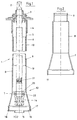
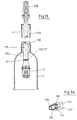
- Figure 1 shows a built-in set 1 in side view and in section.
- This installation set 1 consists of the square bar 2, which is not in the area above reproduced earth surface via a sealing washer 3 with respect to the surrounding Sleeve tube 5, 6 is sealed.
- the edge cap 4 also serves as a seal.
- the sleeve tube is also 5, 6 formed in two parts in order to achieve a telescopability.
- the cylinder part 8 also serves as an insertion end 9 for the sleeve tube 6, so that a continuous protection of the square bar 2 or the square tube 10 ensures is.
- a dirt disk 16 sealing onto the slide 15 is provided in the connection area 13 between the spindle 12 and the coupling sleeve 14 .
- the lower bell edge 17 is on the coupling edge 18 of the dirt disk 16 put on or pushed on, so that here advantageously also an adapter effect is reached.
- Figure 2 illustrates the special design of the bell 7, this here at the upper end 9 to be connected to the sleeve tube 5, 6 another one has a separate ring projection 19, which is also from the inside and from the side the bell 7 ago represents an insertion limit.
- the two parts of the telescopic rod, d. H. the square bar 2 and the square tube 10 can be moved into one another, a locking system 21 being provided is that prevents the two parts from pulling apart too far. By A special design of this locking system 21 is corrosion in this area effectively prevented.
- the square tube 10 is illustrated in FIG. 1 in the coupling sleeve 14 inserted and then by a parallel to the upper edge 20 displaceable Split pin fixed.
- Figures 1 and 2 show an installation set without a so-called spacer.
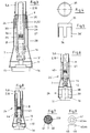
- a spacer 24 shown in FIG pin-free connection between square rod 2, square tube 10 and spindle 12 can be reached.
- Figure 1 is still indicated and this also applies to Figure 3 that in the Coupling sleeve 14 holes are available in which such pins could be inserted if not the spacer shown in Figure 3 and the subsequent figures 24 is used.
- the spacer 24 fills the bell interior 25 above the upper edge 20 of the coupling sleeve 14 quasi.
- FIG. 3 shows an embodiment of the spacer 24 which is distinguished by that not only adjustments in a small grid dimension are possible, but Adaptations to any slide valve types, so that it is not necessary to have the Manufacturer of the installation set should also take into account the special shut-off valve design.
- a spacer 24, which is applied to the square tube 10, is used here Spacer sleeve 27, which distributes a large number of locking grooves over the circumference 28 in height 29, 30.
- Spacer sleeve 27 which distributes a large number of locking grooves over the circumference 28 in height 29, 30.
- Locking profile 31 On these locking grooves 29, 30 is slidably arranged Locking profile 31, which protrudes above the bell 7.
- This locking profile 31 has here Form of a locking sleeve 32 on the lower, inserted into the bell 7 end with Locking rings 33, 34 is equipped.
- the bell 7 or vice versa can Square rod 2 or the square tube 10 can be easily pushed back and forth.
- the spring washer 35 is inserted from above, which in FIGS Figure 5 is also shown in a single view. This spring ring then ensures that the locking rings 33, 34 of the locking sleeve 32 insert into the locking grooves 29, 30, so that the effective connection is created.
- the spring ring 35 has spring feet 36, so that a uniform and relatively easy setting of the locking profile 31 or the locking sleeve 32 possible becomes. In addition, loosening can also be brought about by appropriate rotation, so that changes or adjustments are possible. Beyond that too disassembly easily possible in this way.
- the locking profile or rather the spacer sleeve 27 molded with the locking grooves 29, 30 on the square tube 10 or otherwise connected to it can be injection molded onto the bell 7 become, this being possible in particular in the embodiment according to FIG is where the spring ring 35 with its spring feet 36 can only be rotated accordingly takes effect.
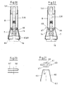
- Figure 6 shows an embodiment in which assembly is also facilitated is that the corresponding valve type or spool type is only taken into account at the construction site must become. This is made possible by the fact that in the area of the dirt disk 16 spacer rings 38, 39 are to be arranged so as to make the necessary adjustment cause.
- the cylinder part is quasi upwards through internal ribs 40, 41 replaced, which is particularly advantageous in terms of weight.
- the order the ribs 40, 41 is illustrated by the section in FIG Ribs 40, 41 are also advantageous in embodiments to be explained further below can also be used.
- FIG. 10 and FIG. 11 are also on the respective Slider type inexpensively adaptable, but not the setting once made there is more to withdraw.
- a spacer sleeve surrounding the square tube 10 48 provided, this spacer sleeve 48 with a plurality of locking lugs 51, 52 is provided.
- This spacer sleeve 48 is attached to the square tube 10.
- a centering aid or a centering ring 50 is provided at the end of the spacer sleeve 48, which causes a fixation is achieved when the coupling sleeve 14 firmly on the slide 15 or the spindle 12 is seated.
- the centering ring 50 sits exactly on the Dome end 49.
- the spacer 24 consists of a sleeve 54, the is inserted below into the cylinder part 8, namely the respective dimension of the Manufacturer dimensioned accordingly long.
- the sleeve 54 consists of two sleeve halves 55, 56, which is illustrated in FIG. 13, wherein here too the recess 47 can be seen, into which the square tube 10 is fitted becomes.
- a disc 58 is shown, which is welded to the square tube 10 and which serves as a spacer 24.
- the disc 58 is depending on the valve type attached at different heights, so that subsequent changes are not are more possible.
- the disk 58 sits exactly in Area of the ring projection 19.
- FIG. 15 and FIG. 16 and also FIG. 17 show a special embodiment, in the spacer in the upper area of internal ribs 40, 41 and in lower region is shown by an inserted sleeve 54.
- the sleeve 54 from below into the corresponding recess or into the cylinder part 8 inserted.
- the sleeve 54 is shown again in Figure 16 while FIG. 17 shows a cross section through the area with the inner ribs 40, 41 reproduces.
- FIGS. 20 and 22 show further embodiments, according to FIG. 20 and 21 a bracket 60 is used as a spacer 24.
- That bracket 60 has a base part 61 with a corresponding recess 47 which of is pushed onto the dome sleeve 14 above.
- the close to the base part 61 catch springs 63, which have hook-shaped outer end lugs 62.
- These outer end noses 62 snap into slot openings 64 of the dirt disk 16, so that then effective locking has been achieved.
- the assembly is facilitated in that the Clamp 60 is pushed open from above, so that it is almost forced into the slot openings 64 of the dirt disk 16 snaps into place without special forces to do that.
- FIG. 22 and FIG. 23 is the same as that according to FIG. 20 different for each valve type.
- a clip 66 serves as a spacer 24, wherein in the bell 7 and the cylinder part 8 holes 68 are provided in the the clasp 66 is inserted with the insertion ends 67. Hole 68 and insertion end 67 are shaped so that the clasp accidentally falls out 66 is not possible. For the rest, however, after the corresponding installation, soil becomes filled around the bell 7 and tamped, so that then the effect of Clasp 66 is no longer at risk.
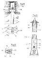
- Figure 24 shows a built-in set 1 in longitudinal section, it being clear that the square rod 2, which is protected against the ground 23 by the sleeve tube 5, 6, extends to the slide 15.
- the upper area is not here for the sake of simplicity reproduced.
- the sleeve tube 5, 6 goes into a bell 7 in the region of the slide 15 via, which is connected via a cylinder part 8 (bell neck) to the sleeve tube 5, 6.
- the square tube 10 is at the bottom, the shut-off valve 11 with the spindle 12 assigned connection area 13 equipped with a coupling sleeve 14.
- This dome sleeve 14 is pushed onto the spindle 12 from above and then through one Spacer 24 locked.
- This spacer 24 is about 3 and 24 around a spacer sleeve 27, the outside with locking grooves 29, 30th is equipped.
- a centering and dirt disk 16 is provided towards the shut-off valve 11. On this centering and dirt disk 16, the bell 7 is attached so that it is also centered at the same time.
- the locking lugs can be placed over the locking rings or deformed or displaced via the locking ring 35 with the spring feet 36 be that they insert into the locking grooves 29, 30.
- the bell interior 25 is otherwise, as shown in FIG. 24, sealed so far that soil 23 or Water cannot penetrate.
- Figure 25 shows the installation set according to Figure 24 in the assembled state.
- the whole Built-in set, d. H. the square rod 2, square tube 10 with the sleeve tube 5, 6, the bell 7 and the centering and dirt disk 16 is from above on the Spindle 12 placed that the coupling sleeve 14 securely surrounds the spindle 12.
- Figure 3 illustrates this.
- FIG. 25 there is a pushing on and also a lifting again according to FIG. 26 the entire installation set 1 of the shut-off valve 11 as long as possible, as the locking ring 35 with the spring feet 36 in the arrangement shown located.
- the locking ring 35 with its Spring feet 36 inserted into the pocket-shaped extension 70 until the outer edge 71 with the peripheral edge 72 is seated on the free end 73 of the cylinder part 8.
- Figure 26 Now press the lower ends of the spring feet 36 on the Locking lugs 33, 34, which are arranged resiliently, so that these are already described Can engage locking grooves 29 or 30.
- the sleeve tube is fixed 5, 6 on the spacer 24 or the spacer sleeve 27. Doing so an accidental pulling out of the locking ring 35 is prevented by this alone that the connector 75, d. H. thus the upper end of the spring feet 36 wedge-shaped is formed and that corresponds to the pocket-shaped here expanded funnel-shaped Training approach 70.
- the locking lugs 33, 34 in the area of pocket-shaped approach 70 have a resilient design, so that they also with the necessary security by the spring feet 36 of the locking ring 35 in the locking groove 29, 30 are pushed in.
- the inside 76 of the pocket-shaped ends Approach 70 in the area of the locking lugs 33, 34 and the outer wall 77 of the sleeve tube 6 takes over their function above, d. H. the function of guiding the spring feet 36.
- the resilient arrangement of the locking lugs 33, 34 and their secure pressing into the respective locking groove 29 or 30 ensured.
- the spacer sleeve is practically in the bell integrated or fixed to the inner wall 78 thereof or simply into the bell 7 inserted.
- This spacer sleeve 48 works here with the end of the coupling sleeve 49 associated centering ring 50 together, by its appropriate training or is deformed by locking parts in the grooves or behind the grooves 51, 52, so to achieve the necessary definition.
- the centering ring 50 has a narrower part 79 and an expansion ring 80, which has the corresponding locking parts 81. Now the expansion ring 80 with the Locking parts 81 on the narrower part 79 of the centering ring 50 moved downward, the locking parts 81 snap behind the grooves 51, 52. The necessary definition or Pull-out protection is reached. Should it be solved for any reason, so a kind of pin 86 is provided. With strain relief, pin 86 lowers and relaxes the locking system. This will place an unnecessary permanent load on the locking elements avoided and a lowering of the coupling sleeve 14 on the spindle 11, 12 achieved. Thus, an optimal power transmission from square bar 2, square tube 10 to the Spindle 11, 12 always guaranteed.
- the assembly state is shown in FIG.
- the centering ring 50 together with the expansion ring 80 rests on the coupling sleeve end 49.
- the locking lugs 81 are in the Grooves 51, 52 of the spacer sleeve 48 are engaged.
- the pin 86 is in the lower one Position. The system is relaxed.
- FIG. 27 shows a state in which the square bar 2, Square tube 10 a force was introduced in the axial direction.
- the dome sleeve 14 presses the expansion ring 80 into the centering ring 50 and the locking lugs 33, 34 are against the spacer sleeve 48 is pressed.
- the path covered by pin 86 shows the path required to lock the system.
- At the moment of pulling up the coupling sleeve 14 is subtracted from the spindle 11, 12 by this amount.
- To Letting go of the square bar 2 and square tube 10 causes the coupling sleeve 14 to settle by gravity back on the spindle 11, 12 in the starting position.
- the configuration according to FIG. 29 is similar, except that here the grooves 51 ', 52' of the Spacer 48 'have a slightly different shape. Is shaped accordingly also the centering ring 50 'with the locking parts 81'.
- the spring feet 84 of the partial rings 82, 83 by moving on the slope of the centering ring 50 in the locking lugs 51, 52 pressed in, so that the desired locking is also achieved here specifically is.
- Both the bell and the sleeve tube 5, 6 consist of a plastic that is unaffected by the surrounding earth 23.
- the spacers 24 in the form of Spacer sleeve 27, 48 and the centering ring and locking ring 35 with the spring feet 36 suitably consist of the same plastic, so that any Influences also with regard to the electrical conductivity u. cannot occur.
- FIG. 30 shows an installation set 1 which is embedded in the soil 102. in the In the upper region of the soil 102, the tar cover is visible, which extends to the upper Edge of the road cap 103 is sufficient.
- This street cap 103 can be made of cast iron or also consist of a special plastic. It is represented by one not shown here Covered so that the head of the square bar 2 from the top to open of the lid, not shown here, is easily accessible.
- the square rod 2 is of a protective tube / sleeve tube made here of plastic 5 surround that up to the spindle of the line slide, not shown here reaches down.
- This protective tube 5, which also starts below Surrounding square tube 10 is surrounded by soil 102.
- the square rod 2 and the square tube 10 form a telescopic rod that as illustrated in FIG. 31, is equipped with a connecting part at the lower end, that can be placed on the square of the spindle.
- the square rod 2 and the square tube 10 are even further back detent spring or locking system 21 to be explained connected by friction.
- the locking system 21 according to FIG. 31 presses against the inner wall 115 of the square tube 10 and provides or generates the necessary friction, paying attention to the details as will be discussed further above.
- FIG. 30 and Figure 31 illustrate that the locking system 21 in a corresponding Hole 113 is housed in the square rod 2.
- This locking system 21st in the form of a spiral spring 110 is equipped at the end with two pressure cylinders 111, 112, which are made of polyamide and ensure that the square bar 2 practical can be pulled out continuously from the square tube 10 without the There is a danger that it will sink again automatically.
- This has continuous adjustment significant advantages, which becomes possible because the coil spring 110 the two Printing cylinder 111, 112 as shown in FIG. 32 pushes apart and thereby against presses the inner wall 115 of the square tube 10 to the necessary friction produce.
- the end pieces 116 or the end faces are the pressure cylinders 111, 112 formed so that they lie close to the inner wall 115 to let.
- a pull-out protection according to FIG. 30 is also implemented, since on Extending 118 of the square tube 10 has a locking hole or locking device 119 is provided. If the square rod 2 is correspondingly far out of the square tube 10 pulled out, the pressure cylinders 111, 112 snap into the locking device 119 and prevent the telescopic rod 107 from being pulled apart further.
- the telescopic rod 107 from a round tube 122 which is a round rod 123 records.
- a transverse bore 124 of the round rod 123 are from one Coil spring 110 pushed apart polyamide pressure cylinders 125, 127.
- This Polyamide printing cylinders 125, 127 have a specially shaped free end 126, which is indicated in Figure 34.
- This free end 126 is oval and lays thus adjoins the corresponding inner wall 115 of the round tube 122, and also Secured by means of tongue and groove, the round rod 123 in the round tube 122 is not twisted can be.
- the round rod 123 can be pulled out of the round tube 122 become. In this case, only the corresponding friction acts as a hindrance, to inadvertently sink the round rod 123 back into the round tube 122 to prevent.
- the upper end of the round bar 123 is provided with a square 128, while at the lower end, the round tube 122 surrounds the corresponding connecting sleeve, which in turn is placed on the spindle of the line slide.
- the polyamide printing cylinders 125, 127 are as a telescopic sleeve according to Figure 34 129 designed to prevent the turning of the Round rod 123 in the round tube 122 from the individual polyamide pressure cylinders 125, 127 the transverse bore 124 are pulled out.
- This telescopic sleeve 129 results in one quasi continuous jacket, the end and that at the free end 126 with the special shape ensures that taking the round tube 122 through the Round rod 123 is done safely.
Landscapes
- Life Sciences & Earth Sciences (AREA)
- Engineering & Computer Science (AREA)
- Hydrology & Water Resources (AREA)
- Public Health (AREA)
- Water Supply & Treatment (AREA)
- Health & Medical Sciences (AREA)
- Mutual Connection Of Rods And Tubes (AREA)
- Mechanically-Actuated Valves (AREA)
- Road Signs Or Road Markings (AREA)
- Finger-Pressure Massage (AREA)
- Quick-Acting Or Multi-Walled Pipe Joints (AREA)
- Valve Housings (AREA)
- Preventing Unauthorised Actuation Of Valves (AREA)
Applications Claiming Priority (6)
| Application Number | Priority Date | Filing Date | Title |
|---|---|---|---|
| DE29516158U | 1995-10-12 | ||
| DE29516158U DE29516158U1 (de) | 1995-10-12 | 1995-10-12 | Einbaugarnitur mit Teleskopstange |
| DE19542062 | 1995-11-13 | ||
| DE1995142062 DE19542062A1 (de) | 1995-11-13 | 1995-11-13 | Einbaugarnitur mit stiftfreier Spindel-Muffen-Verbindung |
| DE19623513 | 1996-06-13 | ||
| DE1996123513 DE19623513A1 (de) | 1995-11-13 | 1996-06-13 | Einbaugarnitur mit stiftfreier Spindel-Muffen-Verbindung und Abstandshalter |
Publications (2)
| Publication Number | Publication Date |
|---|---|
| EP0768434A1 EP0768434A1 (de) | 1997-04-16 |
| EP0768434B1 true EP0768434B1 (de) | 2001-12-19 |
Family
ID=27215638
Family Applications (1)
| Application Number | Title | Priority Date | Filing Date |
|---|---|---|---|
| EP96116121A Expired - Lifetime EP0768434B1 (de) | 1995-10-12 | 1996-10-09 | Einbaugarnitur mit Teleskopstange |
Country Status (5)
| Country | Link |
|---|---|
| EP (1) | EP0768434B1 (cs) |
| AT (1) | ATE211205T1 (cs) |
| CZ (1) | CZ294304B6 (cs) |
| DE (1) | DE59608488D1 (cs) |
| PL (1) | PL182581B1 (cs) |
Families Citing this family (5)
| Publication number | Priority date | Publication date | Assignee | Title |
|---|---|---|---|---|
| PL214341B1 (pl) * | 2009-02-25 | 2013-07-31 | Przed Inzynierii Srodowiska Ekowodrol Spolka Z Ograniczona Odpowiedzialnoscia | Kolumna oslonowa odgalezienia rurociagu cisnieniowego |
| AT512501B1 (de) * | 2012-03-15 | 2013-09-15 | E Hawle Armaturenwerke Gmbh | Einbaugarnitur und Verfahren zu deren Herstellung |
| EP2696117B1 (de) * | 2012-08-07 | 2017-02-01 | Flühs Drehtechnik GmbH | Ventiloberteil |
| CN105571735B (zh) * | 2016-01-21 | 2018-05-29 | 中广核研究院有限公司 | 热电偶密封装置 |
| PL233189B1 (pl) * | 2017-09-19 | 2019-09-30 | Armatura Woda Kanalizacja Spolka Z Ograniczona Odpowiedzialnoscia | Obudowa do zasuw ze zintegrowanym wskaźnikiem otwarcia |
Family Cites Families (3)
| Publication number | Priority date | Publication date | Assignee | Title |
|---|---|---|---|---|
| FR2687418B1 (fr) * | 1992-02-18 | 1998-11-13 | Talavera Jean Paul | Dispositif de bouche a clef telescopique. |
| DE9415364U1 (de) * | 1994-09-22 | 1994-11-17 | P + S Armaturen GmbH, 66482 Zweibrücken | Einbaugarnitur für Armaturen |
| DE4438205C2 (de) * | 1994-10-26 | 1998-12-03 | Michael Buhla | Einbaugarnitur mit Schnellspannkuppelmuffe |
-
1996
- 1996-10-09 EP EP96116121A patent/EP0768434B1/de not_active Expired - Lifetime
- 1996-10-09 AT AT96116121T patent/ATE211205T1/de not_active IP Right Cessation
- 1996-10-09 DE DE59608488T patent/DE59608488D1/de not_active Expired - Lifetime
- 1996-10-10 CZ CZ19962962A patent/CZ294304B6/cs not_active IP Right Cessation
- 1996-10-11 PL PL96316508A patent/PL182581B1/pl not_active IP Right Cessation
Also Published As
| Publication number | Publication date |
|---|---|
| CZ296296A3 (cs) | 1998-06-17 |
| PL316508A1 (en) | 1997-04-14 |
| CZ294304B6 (cs) | 2004-11-10 |
| PL182581B1 (pl) | 2002-01-31 |
| ATE211205T1 (de) | 2002-01-15 |
| EP0768434A1 (de) | 1997-04-16 |
| DE59608488D1 (de) | 2002-01-31 |
Similar Documents
| Publication | Publication Date | Title |
|---|---|---|
| EP2439439B1 (de) | Verbindungselement für eine Fluidverbindung | |
| EP2636803B1 (de) | Unterputzkasten mit Putzdickenausgleich | |
| DE2712118A1 (de) | Gelenkpfanne fuer ein winkelgelenk | |
| DE4438205C2 (de) | Einbaugarnitur mit Schnellspannkuppelmuffe | |
| DE19542062A1 (de) | Einbaugarnitur mit stiftfreier Spindel-Muffen-Verbindung | |
| EP0768434B1 (de) | Einbaugarnitur mit Teleskopstange | |
| DE202011000061U1 (de) | Anschlussverbinder | |
| DE2036215A1 (de) | Rohrleitungssystem | |
| DE29516158U1 (de) | Einbaugarnitur mit Teleskopstange | |
| EP1004713A2 (de) | Abdeck-Rosette | |
| DE19623513A1 (de) | Einbaugarnitur mit stiftfreier Spindel-Muffen-Verbindung und Abstandshalter | |
| EP1895223A1 (de) | Rohrelement für Abwasser- und Entwässerungsleitungen mit einer Revisionsöffnung | |
| DE60010256T2 (de) | Vorrichtung zur verriegelung eines abdeckelementes auf einem stützrahmen | |
| DE102004061168B4 (de) | Einbaugarnitur | |
| DE20008820U1 (de) | Schachtanordnung | |
| EP1769125A1 (de) | Vorrichtung zur verriegelung eines deckels einer schachtabdeckung sowie schachtabdeckung | |
| DE4318125B4 (de) | Hohlkörper für die elektrische Installation | |
| DE102022132044B3 (de) | Einbaugarnitur zur Betätigung einer Unterflurarmatur | |
| DE19711200C2 (de) | Einbaugarnitur mit Multi-Teleskop | |
| DE4234958C2 (de) | Elektrische Hohlwanddose | |
| EP1108820B1 (de) | Einbaugarnitur mit lösbarem Glockenadapter | |
| DE9313860U1 (de) | Vorrichtung zur druckbelastbaren Abdeckung des von einem Baum durchwurzelten Erdreichs | |
| DE9114239U1 (de) | Mauerdurchführung | |
| DE7715023U1 (de) | Betaetigungsvorrichtung fuer anbohrschellen, schieber o.dgl. armaturen | |
| DE202004021842U1 (de) | Kupplung zum Verbinden eines Abzweigrohres mit einem Hauptrohr |
Legal Events
| Date | Code | Title | Description |
|---|---|---|---|
| PUAI | Public reference made under article 153(3) epc to a published international application that has entered the european phase |
Free format text: ORIGINAL CODE: 0009012 |
|
| AK | Designated contracting states |
Kind code of ref document: A1 Designated state(s): AT BE CH DE DK ES FR GB GR IE IT LI LU MC NL PT SE |
|
| 17P | Request for examination filed |
Effective date: 19970823 |
|
| 17Q | First examination report despatched |
Effective date: 19990329 |
|
| RAP1 | Party data changed (applicant data changed or rights of an application transferred) |
Owner name: BUHLA, MICHAEL |
|
| RIN1 | Information on inventor provided before grant (corrected) |
Inventor name: BUHLA, MICHAEL Inventor name: ZEUSNIK, JOACHIM |
|
| GRAG | Despatch of communication of intention to grant |
Free format text: ORIGINAL CODE: EPIDOS AGRA |
|
| GRAG | Despatch of communication of intention to grant |
Free format text: ORIGINAL CODE: EPIDOS AGRA |
|
| GRAH | Despatch of communication of intention to grant a patent |
Free format text: ORIGINAL CODE: EPIDOS IGRA |
|
| GRAH | Despatch of communication of intention to grant a patent |
Free format text: ORIGINAL CODE: EPIDOS IGRA |
|
| GRAA | (expected) grant |
Free format text: ORIGINAL CODE: 0009210 |
|
| AK | Designated contracting states |
Kind code of ref document: B1 Designated state(s): AT BE CH DE DK ES FR GB GR IE IT LI LU MC NL PT SE |
|
| PG25 | Lapsed in a contracting state [announced via postgrant information from national office to epo] |
Ref country code: NL Free format text: LAPSE BECAUSE OF FAILURE TO SUBMIT A TRANSLATION OF THE DESCRIPTION OR TO PAY THE FEE WITHIN THE PRESCRIBED TIME-LIMIT Effective date: 20011219 Ref country code: IT Free format text: LAPSE BECAUSE OF FAILURE TO SUBMIT A TRANSLATION OF THE DESCRIPTION OR TO PAY THE FEE WITHIN THE PRE;WARNING: LAPSES OF ITALIAN PATENTS WITH EFFECTIVE DATE BEFORE 2007 MAY HAVE OCCURRED AT ANY TIME BEFORE 2007. THE CORRECT EFFECTIVE DATE MAY BE DIFFERENT FROM THE ONE RECORDED.SCRIBED TIME-LIMIT Effective date: 20011219 Ref country code: IE Free format text: LAPSE BECAUSE OF FAILURE TO SUBMIT A TRANSLATION OF THE DESCRIPTION OR TO PAY THE FEE WITHIN THE PRESCRIBED TIME-LIMIT Effective date: 20011219 Ref country code: GR Free format text: LAPSE BECAUSE OF FAILURE TO SUBMIT A TRANSLATION OF THE DESCRIPTION OR TO PAY THE FEE WITHIN THE PRESCRIBED TIME-LIMIT Effective date: 20011219 Ref country code: GB Free format text: LAPSE BECAUSE OF FAILURE TO SUBMIT A TRANSLATION OF THE DESCRIPTION OR TO PAY THE FEE WITHIN THE PRESCRIBED TIME-LIMIT Effective date: 20011219 Ref country code: FR Free format text: LAPSE BECAUSE OF FAILURE TO SUBMIT A TRANSLATION OF THE DESCRIPTION OR TO PAY THE FEE WITHIN THE PRESCRIBED TIME-LIMIT Effective date: 20011219 |
|
| REF | Corresponds to: |
Ref document number: 211205 Country of ref document: AT Date of ref document: 20020115 Kind code of ref document: T |
|
| REG | Reference to a national code |
Ref country code: CH Ref legal event code: EP |
|
| REG | Reference to a national code |
Ref country code: GB Ref legal event code: IF02 |
|
| REG | Reference to a national code |
Ref country code: IE Ref legal event code: FG4D Free format text: GERMAN |
|
| REF | Corresponds to: |
Ref document number: 59608488 Country of ref document: DE Date of ref document: 20020131 |
|
| PG25 | Lapsed in a contracting state [announced via postgrant information from national office to epo] |
Ref country code: SE Free format text: LAPSE BECAUSE OF FAILURE TO SUBMIT A TRANSLATION OF THE DESCRIPTION OR TO PAY THE FEE WITHIN THE PRESCRIBED TIME-LIMIT Effective date: 20020319 Ref country code: PT Free format text: LAPSE BECAUSE OF FAILURE TO SUBMIT A TRANSLATION OF THE DESCRIPTION OR TO PAY THE FEE WITHIN THE PRESCRIBED TIME-LIMIT Effective date: 20020319 Ref country code: DK Free format text: LAPSE BECAUSE OF FAILURE TO SUBMIT A TRANSLATION OF THE DESCRIPTION OR TO PAY THE FEE WITHIN THE PRESCRIBED TIME-LIMIT Effective date: 20020319 |
|
| NLV1 | Nl: lapsed or annulled due to failure to fulfill the requirements of art. 29p and 29m of the patents act | ||
| GBV | Gb: ep patent (uk) treated as always having been void in accordance with gb section 77(7)/1977 [no translation filed] |
Effective date: 20011219 |
|
| PG25 | Lapsed in a contracting state [announced via postgrant information from national office to epo] |
Ref country code: ES Free format text: LAPSE BECAUSE OF FAILURE TO SUBMIT A TRANSLATION OF THE DESCRIPTION OR TO PAY THE FEE WITHIN THE PRESCRIBED TIME-LIMIT Effective date: 20020627 |
|
| REG | Reference to a national code |
Ref country code: IE Ref legal event code: FD4D |
|
| PG25 | Lapsed in a contracting state [announced via postgrant information from national office to epo] |
Ref country code: LU Free format text: LAPSE BECAUSE OF NON-PAYMENT OF DUE FEES Effective date: 20021009 Ref country code: AT Free format text: LAPSE BECAUSE OF NON-PAYMENT OF DUE FEES Effective date: 20021009 |
|
| EN | Fr: translation not filed | ||
| PLBE | No opposition filed within time limit |
Free format text: ORIGINAL CODE: 0009261 |
|
| STAA | Information on the status of an ep patent application or granted ep patent |
Free format text: STATUS: NO OPPOSITION FILED WITHIN TIME LIMIT |
|
| PG25 | Lapsed in a contracting state [announced via postgrant information from national office to epo] |
Ref country code: LI Free format text: LAPSE BECAUSE OF NON-PAYMENT OF DUE FEES Effective date: 20021031 Ref country code: CH Free format text: LAPSE BECAUSE OF NON-PAYMENT OF DUE FEES Effective date: 20021031 Ref country code: BE Free format text: LAPSE BECAUSE OF NON-PAYMENT OF DUE FEES Effective date: 20021031 |
|
| 26N | No opposition filed | ||
| BERE | Be: lapsed |
Owner name: *BUHLA MICHAEL Effective date: 20021031 |
|
| PG25 | Lapsed in a contracting state [announced via postgrant information from national office to epo] |
Ref country code: MC Free format text: LAPSE BECAUSE OF NON-PAYMENT OF DUE FEES Effective date: 20030501 |
|
| NLV1 | Nl: lapsed or annulled due to failure to fulfill the requirements of art. 29p and 29m of the patents act | ||
| REG | Reference to a national code |
Ref country code: CH Ref legal event code: PL |
|
| PGFP | Annual fee paid to national office [announced via postgrant information from national office to epo] |
Ref country code: DE Payment date: 20121030 Year of fee payment: 17 |
|
| REG | Reference to a national code |
Ref country code: DE Ref legal event code: R119 Ref document number: 59608488 Country of ref document: DE Effective date: 20140501 |
|
| PG25 | Lapsed in a contracting state [announced via postgrant information from national office to epo] |
Ref country code: DE Free format text: LAPSE BECAUSE OF NON-PAYMENT OF DUE FEES Effective date: 20140501 |