EP0767390B1 - Suchgerät zum Absuchen grosser Flächen - Google Patents
Suchgerät zum Absuchen grosser Flächen Download PDFInfo
- Publication number
- EP0767390B1 EP0767390B1 EP96113544A EP96113544A EP0767390B1 EP 0767390 B1 EP0767390 B1 EP 0767390B1 EP 96113544 A EP96113544 A EP 96113544A EP 96113544 A EP96113544 A EP 96113544A EP 0767390 B1 EP0767390 B1 EP 0767390B1
- Authority
- EP
- European Patent Office
- Prior art keywords
- frame
- search device
- search
- tube
- cable
- Prior art date
- Legal status (The legal status is an assumption and is not a legal conclusion. Google has not performed a legal analysis and makes no representation as to the accuracy of the status listed.)
- Expired - Lifetime
Links
Images


Classifications
-
- G—PHYSICS
- G01—MEASURING; TESTING
- G01V—GEOPHYSICS; GRAVITATIONAL MEASUREMENTS; DETECTING MASSES OR OBJECTS; TAGS
- G01V3/00—Electric or magnetic prospecting or detecting; Measuring magnetic field characteristics of the earth, e.g. declination, deviation
- G01V3/15—Electric or magnetic prospecting or detecting; Measuring magnetic field characteristics of the earth, e.g. declination, deviation specially adapted for use during transport, e.g. by a person, vehicle or boat
Definitions
- the invention relates to a search device for searching Surfaces, especially after metal objects, with a Frame, which has a guide wire, and with a support device.
- Search devices are for a variety of different uses and possibilities known.
- To search large Terrain areas use frames as large as possible, with which a quick search of large areas is possible is.
- a search device of the type mentioned is from the GM 88 00 815 known.
- a modular structure is created Frames assembled to any size.
- the Search loops or search cables are made using elastic Brackets attached to the frame.
- On the face a shoulder strap is attached so that the search device can be comfortably carried by two people.
- the invention has for its object to provide a search device of the type mentioned, which is suitable for searching large areas and at the same time is particularly easy to use and handle.
- the frame is foldable
- that the guide wire also taken up by the frame in the folded state of the frame is that the frame is designed as a polygon frame with a plurality of side pieces and has stabilizing bars that are at most genoso long as the side pieces.
- the guide wire can both inside and on attached to the frame or guided flexibly.
- the support device has one connected to the frame Pipe on.
- the pipe is designed to accommodate a pipe shape adapted evaluation unit and the end of Rohrs has a rotatable area that is functional connected to a tap changer of the evaluation unit is.
- the frame preferably consists of tubular parts that are inside are hollow and in which the cable runs.
- the pipe which forms the frame or the loop linkage preferably made of high-strength carbon fiber materials a particularly light and therefore easy to handle and on the other hand, can take up the guide wire without it being electromagnetic shield.
- the loop linkage is preferably in a hexagonal, in particular formed from six equally long side pieces Form built up.
- a number are also conceivable other geometric shapes, e.g. rectangular, square, round, octagonal or decagonal shapes.
- Specific A matrix-shaped multi-field loop can have advantages in whose segments use individual receive loops, that interact with the large circumferential guide wire.
- the frame on the Length of one of the side pieces foldable or collapsible is.
- the inventively provided go from the corners of the side pieces Stabilizing bars that are at most as long as are the side pieces, so the collapsibility on the To ensure length of the side pieces.
- the preferred hexagonal embodiment thus result in six equilateral Triangles with which a particularly stable structure of the very light frame is made possible.
- the tube can be made telescopic be and the frame or the loop linkage with ropes to be hung on the pipe.
- the operability of the finder is determined by the in the tube accommodated evaluation unit favored.
- the pipe takes especially the batteries for energy supply, the evaluation unit and a tap changer.
- the search device is advantageously in pulse induct: lon technology operated because this procedure has the main advantage has that almost every arbitrarily large search loop on the respective Search electronics can be used. That alone there is an opportunity to create a search device which is used for various search tasks can be.
- the search device can thereby with its large Probe a large area or loop surface can also be used for deep sounding. specially the search electronics used for the fine sounding connected to a smaller coil.
- the search electronics used for the fine sounding connected to a smaller coil In addition to using the Finder with pulse induction technology is also the use possible with modern sine technology.
- the search system according to the invention therefore makes it one single operator possible, approximately three to five times search larger area than previously possible for two operators which the loop had to carry between them. This represents an area search performance not previously achieved represents.
- the coil can also be designed as a compensating system , which is why a continuous middle bar also with a Search cable must be provided.
- Stabilizing bars can fold the frame back in this way be that next to the outer side pieces also the connection of the one running through the middle Get cable in the modified stabilizing bar remains.
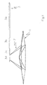
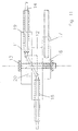
- FIG 1 the overall arrangement with the frame 1, the Support tube 3 and the cable system 2 shown.
- the support tube 3 which is also simply referred to as a pipe from the elements 3a to 3d and is telescopic in and out Extendable.
- the cable system 2 consists of two suspensions with two ropes each, so that a four-point suspension of frame 1 is present.
- the actual frame 1 consists of the circumferential side pieces 4a, 4b, 4c, 4d, 4e and 4f and the of the joints 5a, 5b, 5c, 5d arranged in the corners, 5e and 5f outgoing stabilizing bars 6a, 6b, 6c, 6d, 6e and 6f. These stabilizing bars meet in the center and are attached to a holding plate 7 there.
- the Cable system 2 is point symmetrical to the center on the frame 1 and the support tube 3 attached so that there is a balanced Suspension results.
- the stabilizing bars consist of hollow, high-strength carbon fiber tubes.
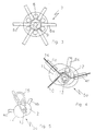
- FIG. 3 A detailed view of the holding plate 7 is shown in Figure 3. Here you can see the running in the holding plate 7 Stabilizing bars 6a to 6f by connecting pins 8 aligned in the two-part holding plate 7 become. A central screw 9 is used to tighten the both parts of the holding plate 7 and thus to the final Fix the stabilizing bars.
- the joint 5a with the search coil connection 10 shown.
- the joint essentially consists of two Plastic washers 11 and 12 with a screw 13 are connected.
- the side pieces run from the joint 4a and 4f, inside of which the search cable 14 is guided becomes.
- the stabilizing rod continues from this joint 6a.
- a third plastic disc in the joint provided, shown in dashed lines in this figure is.
- the joint 5c is shown, which is essentially from the plastic discs 11 and 12 with the Fixing screw 13 exists. On the fixing screw 13 is also a carrier of the loop system 2 with a loop-shaped suspension 15 attached. Still recognizes the approaches of the side pieces 4b and 4c and the Stabilizing bar 6c.
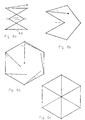
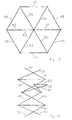
- FIG. 6a to 6d is the unfolding of the frame 1 shown.
- the entire frame was in the Area of the lower side piece 4d concentrated in Figure 6a.
- the stabilizing bars on the side pieces folded towards the center as shown in Figure 6c is.
- the stabilizing tubes open the holding plate 7 screwed in the center of the frame. you receives the stable hexagonal arrangement according to FIG. 6d.
- the search device according to the invention is in pulse induction technology operated and can be a single loop system or a compensating or differentiating loop system included.
- Figure 7 is the telescopic tube and in particular the pipe element 3d shown. Are on this attached the rope elements 2a and 2c, the bottom of the frame 1 are hung.
- FIG. 9 shows a cross section through one of the joints 5 shown.
- the joints consist of the disks 11 and 12 and are secured by a continuous fixing screw 13 held. Both the flexible washers and the screw are made of plastic so that the continuous search cable 14 not by any metal objects in its function is affected.
- On the screw 13 is also a third disk 16 is attached which has a recess 17th for receiving a stabilizing bar.
- a The top view of this joint is again shown in FIG. 10 shown.
- the disks 11 shows a cross section similar to that shown in FIG. 9, however, the joint with the two washers 11 and 12 and the continuous search cable 14 aligned differently is.
- the recesses 18 created by bores and 19 in the disks 12 and 11 serve to accommodate the Side pieces 4, inside which the guide wire is guided becomes.
- the disks 11 and 12 also have a recess 20 on so that the guide wire 14 around the fixing screw 13 led around from one disc to the other can be.
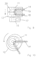
- FIG. 12 shows a partial view of the support tube 3.
- the housing 21 of the tube 3 has on its rear, that is, a rotatable end on the operator side Area 22, which is in connection with the internal tap changer 23 stands.
- the evaluation unit continues to point an electronic cartridge 24 on with the tap changer 23 is connected.
- a battery compartment 25 with six batteries in this case intended.
- An enlarged view of the battery room is shown in Fig. 13.
- a pipe slot 26 is in the pipe provided through which batteries can be filled and be contacted via a spring 27.
- the pipe slot 26 is automatically screwed in the pipe 3 covered. Runs through the battery room Flat cable for connecting the search device. It ends on front end of the electronics housing into a connector.
- the connector with cable is located in the telescopic tube and is therefore protected.
- FIG. 14 An enlarged view of the rear part of the tube 3 is shown in Fig. 14.
- the rotatable part 22nd shown with a fine adjuster 28 and over an axis 29 connected to the internal tap changer 23.
- the signal generator 30 Under the axis 29 of the tap changer is also the signal generator 30 attached, the sound signals through holes 31, the over the entire circumference of the tube 3 are distributed, emerge can.
- the rotatable, switching part of the housing takes at the same time the coaxial adjuster 28 and has taken on two mechanical functions, without the coaxial construction of the mechanics other controls are disturbed.
- the electronics cartridge 24 is arranged. it consists of a cylinder made of insulating material, the two or more cast PCBs. This makes the structure shock-free tropical conditions.
- FIG. 15 Another embodiment of the invention is shown in FIG. 15 shown.
- To build a compensating search loop becomes a guide wire through the middle stabilizing bar 61, 62, 63 guided, when folding the frame not only the connection of the peripheral side pieces 41, 42, 43, 44, 45 and 46, but also the one running through the middle Connection of the stabilizing bars 61, 62 and 63 must be preserved.
- For this is a modification of the Joints compared to the foldable shown in Fig. 6 Frame necessary because there is an additional connection must stay. So the central shown in Fig. 3 must Retaining plate are modified so that two to each other rotatable disks are provided to accommodate the Stabilizing bars 63 and 61 and to carry out the continuous search cable are suitable.
- the central holding plate of this embodiment has a cavity for detachable mounting of the remaining four stabilizing bars 51, 52, 53 and 54.
- the four corner joints on the usual stabilizing bars 51, 52, 53 and 54 are opposite the simple embodiment without compensating Loop unchanged and constructed as shown in Fig. 11 is shown.
- the corner joints are on the middle stabilizing bars 62 and 61 with a additional cable entry that allows it, too Cable from the side pieces 45 and 46 or 42 and 43 in the Introduce stabilizing bars 62 or 61.
- An additional, consisting of two rotatable disks and suitable joint for cable entry is in the middle of the two-part stabilizing rod 62, 63 inserted.
Landscapes
- Life Sciences & Earth Sciences (AREA)
- Engineering & Computer Science (AREA)
- Environmental & Geological Engineering (AREA)
- Geology (AREA)
- Remote Sensing (AREA)
- Physics & Mathematics (AREA)
- General Life Sciences & Earth Sciences (AREA)
- General Physics & Mathematics (AREA)
- Geophysics (AREA)
- Radar Systems Or Details Thereof (AREA)
- Geophysics And Detection Of Objects (AREA)
- Aiming, Guidance, Guns With A Light Source, Armor, Camouflage, And Targets (AREA)
- Unwinding Of Filamentary Materials (AREA)
- Manipulator (AREA)
- Investigating Or Analyzing Materials By The Use Of Electric Means (AREA)
Description
- Fig. 1
- eine perspektivische Gesamtansicht des erfindungsgemäBen Suchgeräts;
- Fig. 2
- eine Draufsicht auf das erfindungsgemäße Suchgerät;
- Figuren 3 bis 5
- vergrößerte Ausschnitte des Suchgeräts gemäß Figur 2;
- Figuren 6a bis d
- den zusammenfaltbaren Rahmen in verschiedenen Stadien des Zusammenlegens;
- Fig. 7
- die Aufhängung des Rahmens am Tragrohr;
- Fig. 8
- eine Detailansicht aus Figur 7;
- Figuren 9, 10 und 11
- weitere Detailansichten der Gelenke des Rahmens;
- Fig. 12
- eine Ansicht des Tragrohres;
- Figuren 13 und 14
- vergrößerte Ausschnittsdarstellungen der Figur 12;
- Figur 15
- einen zusammenfaltbaren Rahmen mit kompensierender Schleife im mittleren Stabilisierungsstab; und
- Figur 16
- Faltung des zusammenlegbaren Rahmens gemäß Figur 15.
Claims (17)
- Suchgerät zum Absuchen von Flächen, insbesondere nach Metallobjekten, mit einem Rahmen, der mindestens ein Suchkabel aufweist, und mit einer Trageinrichtung,
dadurch gekennzeichnet,daß der Rahmen (1) faltbar ausgebildet ist,daß das Suchkabel (14) auch in einem gefalteten Zustand des Rahmens (1) vom Rahmen aufgenommen ist,daß der Rahmen (1) als Polygonrahmen mit einer Mehrzahl von Seitenstücken (4a bis 4f) ausgebildet ist und Stabilisierungsstangen (6a bis 6f) aufweist, die höchstens genauso lang wie die Seitenstücke (4a bis 4f) sind. - Suchgerät nach Anspruch 1,
dadurch gekennzeichnet,daß die Trageinrichtung ein mit dem Rahmen (1) verbundenes Rohr (3) aufweist,daß das Rohr (3) zur Aufnahme einer an die Rohrform angepaßten Auswerteeinheit (23, 24, 25) ausgebildet ist, unddaß das Ende des Rohres (3) einen drehbaren Bereich (22) aufweist, der funktionsmäßig mit einem Schalter (23) der Auswerteeinheit (23, 24, 25) verbunden ist, und eine koaxial angeordnete Feineinstelleinrichtung (28) aufnimmt. - Suchgerät nach einem der vorhergehenden Ansprüche,
dadurch gekennzeichnet, daß der Rahmen (1) im wesentlichen aus Rohren (4a bis 4f, 6a bis 6f) besteht. - Suchgerät nach einem der vorhergehenden Ansprüche,
dadurch gekennzeichnet, daß die Rohre (4a bis 4f, 6a bis 6f) aus Kohlefaseroder Glasfasermaterialien aufgebaut sind. - Suchgerät nach einem der vorhergehenden Ansprüche,
dadurch gekennzeichnet, daß der Rahmen (1) sechs Seitenstücke (4a bis 4f) aufweist. - Suchgerät nach einem der vorhergehenden Ansprüche,
dadurch gekennzeichnet, daß der Rahmen (1) auf die Länge eines der Seitenstücke (4) zusammenlegbar ist. - Suchgerät nach einem der vorhergehenden Ansprüche,
dadurch gekennzeichnet, daß das Rohr (3) der Trageinrichtung teleskopartig ausziehbar ist. - Suchgerät nach einem der vorhergehenden Ansprüche,
dadurch gekennzeichnet, daß der Rahmen (1) mit Seilen (2) am Rohr (3) aufgehängt ist. - Suchgerät nach einem der vorhergehenden Ansprüche,
dadurch gekennzeichnet, daß die Seile (2) am Rohr (3) aufwickelbar sind. - Suchgerät nach einem der vorhergehenden Ansprüche,
dadurch gekennzeichnet, daß das Suchgerät mit Pulsinduktionstechnik ausgestattet ist. - Suchgerät nach einem der vorhergehenden Ansprüche,
dadurch gekennzeichnet, daß eine zentrale Halteplatte (7) vorgesehen ist, in der die Stabilisierungsstäbe (6a bis 6f) aufnehmbar und durch eine zentrale Schraube (9) festlegbar sind. - Suchgerät nach einem der vorhergehenden Ansprüche,
dadurch gekennzeichnet, daß die Seitenstücke (4a bis 4f) des Rahmens (1) Gelenke (5a bis 5f) aufweisen, die aus drei übereinander angeordneten und mit einer Kunststoffschraube (13) verbundenen Kunststoffscheiben (11, 12, 16) bestehen, von denen zwei zur Aufnahme je eines Seitenstücks und eine zur Aufnahme eines Stabilisierungsstabs vorgesehen sind. - Suchgerät nach Anspruch 1,
dadurch gekennzeichnet, daß mindestens ein Suchkabel im Inneren des Rahmens angeordnet ist und/oder auf den Rahmen aufgelegt und fixiert ist. - Suchgerät nach Anspruch 13,
dadurch gekennzeichnet, daß zusätzlich zu einer im Inneren des Rahmens angeordneten Schleife, z.B. einem Suchkabel, mindestens eine weitere Schleife außen am Rahmen vorgesehen ist. - Suchgerät nach einem der vorhergehenden Ansprüche,
dadurch gekennzeichnet, daß zwei Stabilisierungsstäbe (61, 62 und 63) zur Aufnahme einer zusätzlichen Suchschleife und/oder einer kompensierenden Schleifenanordnung ausgebildet sind. - Suchgerät nach Anspruch 15,
dadurch gekennzeichnet, daß einer der zur Aufnahme des Suchkabels ausgelegten Stabilisierungsstäbe ein zusätzliches, insbesondere zentral angeordnetes Gelenk aufweist. - Suchgerät nach Anspruch 15 oder 16,
dadurch gekennzeichnet, daß die zentrale Halteplatte zur lösbaren Aufnahme von vier Stabilisierungsstäben (51, 52, 53, 54) und zur drehbaren Halterung der kabelführenden Stabilisierungsstäbe (61, 62 und 63) vorgesehen ist.
Applications Claiming Priority (2)
| Application Number | Priority Date | Filing Date | Title |
|---|---|---|---|
| DE29514494U | 1995-09-08 | ||
| DE29514494U DE29514494U1 (de) | 1995-09-08 | 1995-09-08 | Suchgerät zum Absuchen großer Flächen |
Publications (3)
| Publication Number | Publication Date |
|---|---|
| EP0767390A2 EP0767390A2 (de) | 1997-04-09 |
| EP0767390A3 EP0767390A3 (de) | 1998-04-01 |
| EP0767390B1 true EP0767390B1 (de) | 2002-03-20 |
Family
ID=8012814
Family Applications (1)
| Application Number | Title | Priority Date | Filing Date |
|---|---|---|---|
| EP96113544A Expired - Lifetime EP0767390B1 (de) | 1995-09-08 | 1996-08-23 | Suchgerät zum Absuchen grosser Flächen |
Country Status (4)
| Country | Link |
|---|---|
| EP (1) | EP0767390B1 (de) |
| AT (1) | ATE214809T1 (de) |
| AU (1) | AU708358B2 (de) |
| DE (2) | DE29514494U1 (de) |
Cited By (2)
| Publication number | Priority date | Publication date | Assignee | Title |
|---|---|---|---|---|
| DE202012003223U1 (de) | 2012-03-29 | 2012-06-12 | Klaus Ebinger | Schleifenrahmen |
| DE202015003655U1 (de) | 2015-05-21 | 2015-07-02 | Sensys Sensorik & Systemtechnologie Gmbh | Tragegestell |
Families Citing this family (4)
| Publication number | Priority date | Publication date | Assignee | Title |
|---|---|---|---|---|
| DE29721864U1 (de) * | 1997-12-10 | 1998-01-29 | Fa. Ing. Klaus Ebinger, 51149 Köln | Rahmen für ein Suchgerät |
| DE29811404U1 (de) * | 1998-06-25 | 1998-09-10 | Fa. Ing. Klaus Ebinger, 51149 Köln | Sondenvorrichtung |
| DE102013011353B4 (de) * | 2013-07-08 | 2016-02-18 | Thorsten Straub | Vorrichtung zum erdbodenparallelen Führen der Rahmensonde eines Pulsinduktions-Metalldetektors |
| DE202015102891U1 (de) | 2015-06-03 | 2015-07-17 | Klaus Ebinger | Suchgerät |
Family Cites Families (6)
| Publication number | Priority date | Publication date | Assignee | Title |
|---|---|---|---|---|
| DE393147C (de) * | 1923-07-05 | 1924-04-03 | Arno Brasch | Zusammenlegbare Rahmenantenne fuer Funkentelegraphie |
| GB315964A (en) * | 1928-06-14 | 1929-07-25 | Eric J Lever Trix Ltd | Improvements in or relating to frame or loop aerials for radio sets |
| DE922973C (de) * | 1952-12-04 | 1955-01-31 | Heinrich Sewerin | Einstellbarer Sucher fuer kleine und grosse Eisenteile |
| DE1623110A1 (de) * | 1967-08-24 | 1971-04-01 | Waldemar Lindenberg | Vorrichtung fuer die elektrische Ortung von Gegenstaenden aus Metall |
| JPS5627508A (en) * | 1979-08-15 | 1981-03-17 | Pioneer Electronic Corp | Loop antenna |
| DE8800815U1 (de) * | 1988-01-25 | 1988-06-30 | Ebinger, Klaus, 5000 Köln | Suchrahmen für ein Metallsuchgerät |
-
1995
- 1995-09-08 DE DE29514494U patent/DE29514494U1/de not_active Expired - Lifetime
-
1996
- 1996-08-23 EP EP96113544A patent/EP0767390B1/de not_active Expired - Lifetime
- 1996-08-23 AT AT96113544T patent/ATE214809T1/de not_active IP Right Cessation
- 1996-08-23 DE DE59608909T patent/DE59608909D1/de not_active Expired - Fee Related
- 1996-09-06 AU AU64471/96A patent/AU708358B2/en not_active Ceased
Cited By (4)
| Publication number | Priority date | Publication date | Assignee | Title |
|---|---|---|---|---|
| DE202012003223U1 (de) | 2012-03-29 | 2012-06-12 | Klaus Ebinger | Schleifenrahmen |
| EP2645134A2 (de) | 2012-03-29 | 2013-10-02 | Klaus Ebinger | Schleifenrahmen |
| EP2645134A3 (de) * | 2012-03-29 | 2017-03-08 | Klaus Ebinger | Schleifenrahmen |
| DE202015003655U1 (de) | 2015-05-21 | 2015-07-02 | Sensys Sensorik & Systemtechnologie Gmbh | Tragegestell |
Also Published As
| Publication number | Publication date |
|---|---|
| ATE214809T1 (de) | 2002-04-15 |
| AU6447196A (en) | 1997-03-13 |
| EP0767390A3 (de) | 1998-04-01 |
| EP0767390A2 (de) | 1997-04-09 |
| AU708358B2 (en) | 1999-08-05 |
| DE59608909D1 (de) | 2002-04-25 |
| DE29514494U1 (de) | 1996-01-25 |
Similar Documents
| Publication | Publication Date | Title |
|---|---|---|
| DE9307373U1 (de) | Niedervolt-Leuchtanlage | |
| DE7700829U1 (de) | Elektrokabel | |
| DE3434224A1 (de) | Demontierbare rahmen | |
| EP0767390B1 (de) | Suchgerät zum Absuchen grosser Flächen | |
| DE3030162C2 (de) | Gehäuse für elektrotechnische Geräte, insbesondere für die elektrische Nachrichtentechnik | |
| DE8800494U1 (de) | Elektrischer Rauschabsorber | |
| DE69834370T2 (de) | Kupplungsmechanismus für TE011- und TE01delta- Mode-Resonatoren | |
| DE112011102720T5 (de) | Rahmenstruktur zum Errichten einer Bühne | |
| EP0957377B1 (de) | Vorrichtung und Verfahren zum Orten von Metallteilen | |
| DE2541247C3 (de) | Kupplungselement zum Verbinden eines optischen Übertragungselementes und eines aktiven oder passiven optoelektrischen Elementes | |
| EP0922969B1 (de) | Rahmen für ein Suchgerät | |
| DE3232131C1 (de) | Bausatz zur Erstellung eines Saeulenstativs | |
| DE2247253A1 (de) | Kabelmuffe | |
| EP0110286B1 (de) | Bausatz zur Halterung einer Lampe an einem Gartenschirm | |
| DE102007008328A1 (de) | Mast | |
| DE202024000776U1 (de) | Vorrichtung zur Bearbeitung von Innenflächen von Rohrleitungen | |
| DE19859473A1 (de) | Geräteständer | |
| DE9420034U1 (de) | Seilkreuzklemme | |
| DE4012614A1 (de) | Verbindungselement | |
| EP0852922A1 (de) | Verbindungsvorrichtung | |
| EP0294764B1 (de) | Lichtwellenleitersteckverbindungen | |
| EP1010991B1 (de) | Torsonde | |
| DE295110C (de) | ||
| DE202016005670U1 (de) | Modulare Kletterstruktur | |
| DE7404904U (de) | Eckverbindung zweier Rohre aus Metall |
Legal Events
| Date | Code | Title | Description |
|---|---|---|---|
| PUAI | Public reference made under article 153(3) epc to a published international application that has entered the european phase |
Free format text: ORIGINAL CODE: 0009012 |
|
| AK | Designated contracting states |
Kind code of ref document: A2 Designated state(s): AT DE FR GB IT |
|
| PUAL | Search report despatched |
Free format text: ORIGINAL CODE: 0009013 |
|
| AK | Designated contracting states |
Kind code of ref document: A3 Designated state(s): AT DE FR GB IT |
|
| 17P | Request for examination filed |
Effective date: 19980902 |
|
| 17Q | First examination report despatched |
Effective date: 20001027 |
|
| GRAG | Despatch of communication of intention to grant |
Free format text: ORIGINAL CODE: EPIDOS AGRA |
|
| GRAG | Despatch of communication of intention to grant |
Free format text: ORIGINAL CODE: EPIDOS AGRA |
|
| GRAH | Despatch of communication of intention to grant a patent |
Free format text: ORIGINAL CODE: EPIDOS IGRA |
|
| GRAH | Despatch of communication of intention to grant a patent |
Free format text: ORIGINAL CODE: EPIDOS IGRA |
|
| REG | Reference to a national code |
Ref country code: GB Ref legal event code: IF02 |
|
| GRAA | (expected) grant |
Free format text: ORIGINAL CODE: 0009210 |
|
| AK | Designated contracting states |
Kind code of ref document: B1 Designated state(s): AT DE FR GB IT |
|
| PG25 | Lapsed in a contracting state [announced via postgrant information from national office to epo] |
Ref country code: IT Free format text: LAPSE BECAUSE OF FAILURE TO SUBMIT A TRANSLATION OF THE DESCRIPTION OR TO PAY THE FEE WITHIN THE PRESCRIBED TIME-LIMIT;WARNING: LAPSES OF ITALIAN PATENTS WITH EFFECTIVE DATE BEFORE 2007 MAY HAVE OCCURRED AT ANY TIME BEFORE 2007. THE CORRECT EFFECTIVE DATE MAY BE DIFFERENT FROM THE ONE RECORDED. Effective date: 20020320 Ref country code: GB Free format text: LAPSE BECAUSE OF FAILURE TO SUBMIT A TRANSLATION OF THE DESCRIPTION OR TO PAY THE FEE WITHIN THE PRESCRIBED TIME-LIMIT Effective date: 20020320 Ref country code: FR Free format text: LAPSE BECAUSE OF FAILURE TO SUBMIT A TRANSLATION OF THE DESCRIPTION OR TO PAY THE FEE WITHIN THE PRESCRIBED TIME-LIMIT Effective date: 20020320 |
|
| REF | Corresponds to: |
Ref document number: 214809 Country of ref document: AT Date of ref document: 20020415 Kind code of ref document: T |
|
| REF | Corresponds to: |
Ref document number: 59608909 Country of ref document: DE Date of ref document: 20020425 |
|
| PG25 | Lapsed in a contracting state [announced via postgrant information from national office to epo] |
Ref country code: AT Free format text: LAPSE BECAUSE OF NON-PAYMENT OF DUE FEES Effective date: 20020823 |
|
| GBV | Gb: ep patent (uk) treated as always having been void in accordance with gb section 77(7)/1977 [no translation filed] |
Effective date: 20020320 |
|
| EN | Fr: translation not filed | ||
| PLBE | No opposition filed within time limit |
Free format text: ORIGINAL CODE: 0009261 |
|
| STAA | Information on the status of an ep patent application or granted ep patent |
Free format text: STATUS: NO OPPOSITION FILED WITHIN TIME LIMIT |
|
| 26N | No opposition filed |
Effective date: 20021223 |
|
| PGFP | Annual fee paid to national office [announced via postgrant information from national office to epo] |
Ref country code: DE Payment date: 20030829 Year of fee payment: 8 |
|
| PG25 | Lapsed in a contracting state [announced via postgrant information from national office to epo] |
Ref country code: DE Free format text: LAPSE BECAUSE OF NON-PAYMENT OF DUE FEES Effective date: 20050301 |