EP0767353B1 - Method to equalise the temperature in a heating furnace with a controlled-oxidisation ambient and heating furnace carrying out the method - Google Patents
Method to equalise the temperature in a heating furnace with a controlled-oxidisation ambient and heating furnace carrying out the method Download PDFInfo
- Publication number
- EP0767353B1 EP0767353B1 EP96112927A EP96112927A EP0767353B1 EP 0767353 B1 EP0767353 B1 EP 0767353B1 EP 96112927 A EP96112927 A EP 96112927A EP 96112927 A EP96112927 A EP 96112927A EP 0767353 B1 EP0767353 B1 EP 0767353B1
- Authority
- EP
- European Patent Office
- Prior art keywords
- furnace
- scale
- burners
- layer
- rollers
- Prior art date
- Legal status (The legal status is an assumption and is not a legal conclusion. Google has not performed a legal analysis and makes no representation as to the accuracy of the status listed.)
- Expired - Lifetime
Links
Images


Classifications
-
- F—MECHANICAL ENGINEERING; LIGHTING; HEATING; WEAPONS; BLASTING
- F27—FURNACES; KILNS; OVENS; RETORTS
- F27D—DETAILS OR ACCESSORIES OF FURNACES, KILNS, OVENS, OR RETORTS, IN SO FAR AS THEY ARE OF KINDS OCCURRING IN MORE THAN ONE KIND OF FURNACE
- F27D25/00—Devices or methods for removing incrustations, e.g. slag, metal deposits, dust; Devices or methods for preventing the adherence of slag
- F27D25/001—Devices or methods for removing incrustations, e.g. slag, metal deposits, dust; Devices or methods for preventing the adherence of slag comprising breaking tools, e.g. hammers, drills, scrapers
-
- C—CHEMISTRY; METALLURGY
- C21—METALLURGY OF IRON
- C21D—MODIFYING THE PHYSICAL STRUCTURE OF FERROUS METALS; GENERAL DEVICES FOR HEAT TREATMENT OF FERROUS OR NON-FERROUS METALS OR ALLOYS; MAKING METAL MALLEABLE, e.g. BY DECARBURISATION OR TEMPERING
- C21D1/00—General methods or devices for heat treatment, e.g. annealing, hardening, quenching or tempering
- C21D1/34—Methods of heating
- C21D1/52—Methods of heating with flames
-
- C—CHEMISTRY; METALLURGY
- C21—METALLURGY OF IRON
- C21D—MODIFYING THE PHYSICAL STRUCTURE OF FERROUS METALS; GENERAL DEVICES FOR HEAT TREATMENT OF FERROUS OR NON-FERROUS METALS OR ALLOYS; MAKING METAL MALLEABLE, e.g. BY DECARBURISATION OR TEMPERING
- C21D11/00—Process control or regulation for heat treatments
-
- F—MECHANICAL ENGINEERING; LIGHTING; HEATING; WEAPONS; BLASTING
- F27—FURNACES; KILNS; OVENS; RETORTS
- F27B—FURNACES, KILNS, OVENS, OR RETORTS IN GENERAL; OPEN SINTERING OR LIKE APPARATUS
- F27B9/00—Furnaces through which the charge is moved mechanically, e.g. of tunnel type; Similar furnaces in which the charge moves by gravity
- F27B9/14—Furnaces through which the charge is moved mechanically, e.g. of tunnel type; Similar furnaces in which the charge moves by gravity characterised by the path of the charge during treatment; characterised by the means by which the charge is moved during treatment
- F27B9/20—Furnaces through which the charge is moved mechanically, e.g. of tunnel type; Similar furnaces in which the charge moves by gravity characterised by the path of the charge during treatment; characterised by the means by which the charge is moved during treatment the charge moving in a substantially straight path tunnel furnace
- F27B9/24—Furnaces through which the charge is moved mechanically, e.g. of tunnel type; Similar furnaces in which the charge moves by gravity characterised by the path of the charge during treatment; characterised by the means by which the charge is moved during treatment the charge moving in a substantially straight path tunnel furnace being carried by a conveyor
- F27B9/2407—Furnaces through which the charge is moved mechanically, e.g. of tunnel type; Similar furnaces in which the charge moves by gravity characterised by the path of the charge during treatment; characterised by the means by which the charge is moved during treatment the charge moving in a substantially straight path tunnel furnace being carried by a conveyor the conveyor being constituted by rollers (roller hearth furnace)
-
- F—MECHANICAL ENGINEERING; LIGHTING; HEATING; WEAPONS; BLASTING
- F27—FURNACES; KILNS; OVENS; RETORTS
- F27B—FURNACES, KILNS, OVENS, OR RETORTS IN GENERAL; OPEN SINTERING OR LIKE APPARATUS
- F27B9/00—Furnaces through which the charge is moved mechanically, e.g. of tunnel type; Similar furnaces in which the charge moves by gravity
- F27B9/30—Details, accessories, or equipment peculiar to furnaces of these types
- F27B9/40—Arrangements of controlling or monitoring devices
-
- C—CHEMISTRY; METALLURGY
- C21—METALLURGY OF IRON
- C21D—MODIFYING THE PHYSICAL STRUCTURE OF FERROUS METALS; GENERAL DEVICES FOR HEAT TREATMENT OF FERROUS OR NON-FERROUS METALS OR ALLOYS; MAKING METAL MALLEABLE, e.g. BY DECARBURISATION OR TEMPERING
- C21D9/00—Heat treatment, e.g. annealing, hardening, quenching or tempering, adapted for particular articles; Furnaces therefor
- C21D9/0081—Heat treatment, e.g. annealing, hardening, quenching or tempering, adapted for particular articles; Furnaces therefor for slabs; for billets
-
- F—MECHANICAL ENGINEERING; LIGHTING; HEATING; WEAPONS; BLASTING
- F27—FURNACES; KILNS; OVENS; RETORTS
- F27B—FURNACES, KILNS, OVENS, OR RETORTS IN GENERAL; OPEN SINTERING OR LIKE APPARATUS
- F27B9/00—Furnaces through which the charge is moved mechanically, e.g. of tunnel type; Similar furnaces in which the charge moves by gravity
- F27B9/02—Furnaces through which the charge is moved mechanically, e.g. of tunnel type; Similar furnaces in which the charge moves by gravity of multiple-track type; of multiple-chamber type; Combinations of furnaces
- F27B9/029—Multicellular type furnaces constructed with add-on modules
-
- F—MECHANICAL ENGINEERING; LIGHTING; HEATING; WEAPONS; BLASTING
- F27—FURNACES; KILNS; OVENS; RETORTS
- F27D—DETAILS OR ACCESSORIES OF FURNACES, KILNS, OVENS, OR RETORTS, IN SO FAR AS THEY ARE OF KINDS OCCURRING IN MORE THAN ONE KIND OF FURNACE
- F27D99/00—Subject matter not provided for in other groups of this subclass
- F27D2099/0085—Accessories
- F27D2099/0093—Means to collect ashes or dust, e.g. vessels
-
- Y—GENERAL TAGGING OF NEW TECHNOLOGICAL DEVELOPMENTS; GENERAL TAGGING OF CROSS-SECTIONAL TECHNOLOGIES SPANNING OVER SEVERAL SECTIONS OF THE IPC; TECHNICAL SUBJECTS COVERED BY FORMER USPC CROSS-REFERENCE ART COLLECTIONS [XRACs] AND DIGESTS
- Y10—TECHNICAL SUBJECTS COVERED BY FORMER USPC
- Y10T—TECHNICAL SUBJECTS COVERED BY FORMER US CLASSIFICATION
- Y10T29/00—Metal working
- Y10T29/49—Method of mechanical manufacture
- Y10T29/4998—Combined manufacture including applying or shaping of fluent material
- Y10T29/49988—Metal casting
- Y10T29/49991—Combined with rolling
Definitions
- This invention concerns a method to equalise the temperature in a heating furnace with a controlled-oxidisation ambient, as set forth in the relative main claim.
- the invention concerns also the heating furnace which carries out the method.
- This invention is applied to a line for the rolling of slabs, particularly thin slabs, in cooperation with furnaces performing heating, temperature-maintaining and/or temperature-equalisation which are arranged in an intermediate position between the casting machine and the rolling train.
- the state of the art of rolling lines covers the requirement of arranging furnaces performing heating, temperature-maintaining and/or temperature-equalisation between the continuous casting machines and the rolling train.
- furnaces have the purpose of preventing reductions of temperature of the product being fed at low casting speeds and of preparing that product for the rolling process carried out downstream.
- these furnaces perform a primary task of maintaining the temperature at a high value and of equalising the temperature at the core and at the surface of the product.
- furnaces normally cooperate upstream with a shears, if it is included.
- These heating furnaces are normally equipped with a plurality of burners evenly spread along the length of the furnace and normally positioned on the sidewalls in a high position, and are also equipped with an advantageously mating plurality of intakes or aspiration outlets to discharge the fumes.
- FR-A-1 559 355 discloses a furnace for heating and equalising the temperature of slabs, which is able to be disposed between a continuous casting machine and a rolling train, to uniformly heat the slabs to a predetermined temperature, wherein upper burners, lower burners and lateral or marginal burners are provided in the furnace to cooperate with the slabs passing therethrough.
- the modification of the temperature of the slabs causes a removal of the scales from the surfaces thereof inside the furnace.
- the burners are generally made to work so as to ensure a neutral, or even partly reducing, atmosphere within the furnace.
- the layer of scale thus formed consists mainly of molecules of FeO, which are very resistant and hard to remove from the surface of the slab.
- the fumes and gases which have to lap the product being fed so as to ensure the heating of the product and the equalisation of its temperature tend to be kept in a high position far from the product, particularly in the zones between one aspiration outlet and the adjacent one.
- This situation has the effect that the heat generated by the burners is not transferred effectively and evenly onto the product to be heated, and the result, in particular, is that the upper surface of the product within the heating furnace undergoes a more intense action than its lower surface.
- the purpose of the invention is to carry out within a heating and/or temperature-maintaining furnace a temperature-equalisation method in a strongly oxidising ambient such as will permit the formation, on the surface of the slab, of a layer of scale required both in terms of thickness and in terms of chemical composition, the scale therefore being more readily removable by means of an action carried out downstream.
- Another purpose of the invention is to make possible the achieving of temperature and technological conditions which are substantially uniform over the whole surface of the product to be heated and/or to have its temperature maintained.
- Another purpose of the invention is to embody a heating furnace which enables the above thermal and technological conditions to be achieved and which enables excellent working conditions to be obtained for the supporting rollers.
- the heating and temperature-maintaining furnace according to the invention is located preferably in a casting line which provides downstream of the continuous casting machine a controlled pre-rolling process performed immediately below the outlet of the mould.
- This furnace comprises conventionally a plurality of burners, which are advantageously evenly distributed along the length of the furnace and have their relative outlet positioned on the sidewalls of the furnace in a high position.
- the burners are caused to function in such a way as to produce within the furnace a controlled and strongly oxidising atmosphere suitable to obtain on the surface of the slab a required conversion of the FeO molecules into Fe 2 O 3 molecules.
- separation baffles are included in an intermediate position between two adjacent burners and extend vertically to a position close to the product to be heated within the furnace.
- baffles in cooperation with the underlying aspiration intakes perform a task of directing and conveying the fumes and gases emitted by the burners so as to compel those fumes and gases to lap in a more effective and even manner the product to be heated.
- baffles Furthermore, the action of these baffles causes the fumes and gases to surround the product fully and to lap all the surfaces of the product in a substantially uniform manner; this situation causes a double working and technological advantage.
- the first advantage is achieved in terms of equalisation of the temperature over the whole surface of the product.
- the second advantage is achieved in terms of causing uniformity both as regards the thickness and also the chemical composition of the layer of scale which becomes formed on the surface of the product.
- a further advantage is achieved by dividing the heating furnace into two or more units between which a descaling assembly is placed.
- a descaling assembly is arranged substantially in the zone in which the growth of the thickness of the scale becomes slower, and is placed between two separate units of the heating furnace and removes the formed layer of scale, thus bringing the surface of the product back to a condition of substantial absence of scale.
- three or even more descaling assemblies may be included and be associated with as many separate units of the heating furnace along a conventional length of about 80 metres.
- This embodiment enables the growth of the scale to be kept under control in a very accurate manner in terms both of thickness and of chemical composition, at the same time carrying out and accentuating the oxidisation process within the furnace and thus making more effective and easier the operations of removal of the scale at the outlet of the furnace.
- a means is included in cooperation with a funnel-shaped outlet used for discharge of the scale, this outlet being placed below the supporting rollers feeding the product, and removes the scale from the periphery of the rings which support the product to be heated and which are associated with the supporting rollers.
- this means comprises milling or grinding means which are associated with movable arms that enable the milling or grinding means to be positioned in cooperation with the supporting rings.
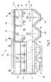
- a heating and/or temperature-maintaining furnace 10 shown in the attached figures comprises an insulated chamber 11 associated with a supporting and feeding surface defined by a plurality of rollers 12.
- the rollers 12 include respective shafts 13 fitted in bearings 14 located outside the insulated chamber 11; these shafts 13 have one end associated with a drive means 15.
- the furnace 10 includes at its ends doors 16 which can be opened, and cooperates on its lower side with a refractory base 17.
- the furnace 10 comprises a plurality of burners 18, which are advantageously evenly distributed along the length of the furnace 10 and of which the outlets face towards the inside of the furnace 10.
- the burners 18 are fed so as to emit fumes and gases having a composition which will create within the furnace 10 a strongly oxidising atmosphere; this situation makes possible the starting and accentuating of conversion by oxidisation of the molecules of FeO into Fe 2 O 3 so as to obtain on the surface of the slab 19 a desired and controlled layer of scale, which is not strong and can be readily removed.
- aspiration intakes 21 which have the purpose of aspirating downwards the heating fumes and gases referenced with 23 and emitted by the burners 18.
- diversion means in the form of separation baffles 20 are included in cooperation with the burners 18 and with the aspiration intakes 21 and have the task of conveying the fumes and gases 23 so as to surround the slab 19, thus providing a uniform heating action over the whole surface of the slab 19.
- Fig.1 shows in this case that the furnace 10 is structured in three separate units, 10a, 10b and 10c respectively positioned in sequence and connected by intermediate insulated chambers 111.
- Each furnace unit 10a, 10b and 10c comprises at its inlet and at its outlet barriers 37, which reduce the outward dispersion of heat from the furnace 10.
- the furnace 10 is structured with two units, or else four units or more.
- the descaling assembly 22 has the task of removing the layer of scale which has formed in the first segment of the furnace 10, thus bringing the surface conditions of the slab 19 back to a condition substantially the same as that at the inlet of the furnace 10.
- the thickness of the scale grows progressively at a very high speed until it reaches a value S1 and is then stabilised or possibly grows at a much slower speed (see Fig.2).
- a first descaling assembly 22a is included downstream of the first unit 10a of the furnace, substantially at the point where the value S1 is reached, and removes completely the layer of scale.
- the product is then fed into the second unit 10b of the furnace, and the layer of scale grows again up to the thickness S1 and is then removed by a second descaling assembly 22b.
- This embodiment makes possible a very precise and accurate control of the formation of the layer of scale on the surface of the slab 19 and also a controlled adjustment of the oxidisation reactions, which enable a scale to be obtained which can be removed more easily from the surface of the slab 19.
- an assembly 31 suitable to measure the thickness of the remaining layer of scale after the removal operation may be included in cooperation with, and downstream of, each of the descaling assemblies 22.
- an assembly 31 (not shown here) to measure the thickness of the layer of scale may also be included immediately upstream of each descaling assembly 22.
- these assemblies 31 to measure the layer of scale may be connected by means of an actuation and control unit to the burners 18 so as to alter the working and feeding parameters of the burners 18 according to the detecting of an incorrect layer of scale.
- collection intakes 24 shaped as funnels are positioned below the rollers 12 and have the purpose of collecting and conveying the scale and other impurities released from the surface of the slab 19 and from the surface of the rollers 12 during the heat treatment carried out within the furnace 10.
- a removal means 25 is included in cooperation with the collection intakes 24 and is suitable to remove the scale that is generated on the surface of rings 35 which are associated with the surface of the rollers 12 and which have the task of supporting the slab 19.
- the removal means 25 comprises a trolley 26 able to run on wheels 27 and associated with a base plate 28.
- the trolley 26 can be moved longitudinally on the base plate 28 along the space left available by the dimensions of the collection intakes 24.
- a telescopically extensible arm 30 is fitted on the trolley 26 and bears scale removal means, which in this case consist of circular grinding wheels 32.
- a pair of circular grinding wheels 32 are included and are located opposite to each other on each side of the arm 30.
- the trolley 26 can also be traversed transversely to the furnace 10 in the directions shown with the arrows 34 so as to bring the circular grinding wheels 32 into cooperation with all the rings 35 fitted to one single roller 12.
- each removal means 25 tends a pair of rollers 12, the arm 30 can be caused to oscillate in the longitudinal direction 33 (Fig.3) on an articulated joint 38 so as to tend both the rollers 12 of the pair of rollers.
- the arm 30 in its retracted position is withdrawn from the collection intake 24 and enables that intake 24 to be closed by slide valve means 29.
- a positionable protective screen 36 is included advantageously in cooperation with the removal means 25.
Landscapes
- Engineering & Computer Science (AREA)
- Chemical & Material Sciences (AREA)
- Mechanical Engineering (AREA)
- General Engineering & Computer Science (AREA)
- Organic Chemistry (AREA)
- Crystallography & Structural Chemistry (AREA)
- Materials Engineering (AREA)
- Metallurgy (AREA)
- Physics & Mathematics (AREA)
- Thermal Sciences (AREA)
- Tunnel Furnaces (AREA)
- Control Of Heat Treatment Processes (AREA)
- Control Of Temperature (AREA)
- Furnace Details (AREA)
- Feeding, Discharge, Calcimining, Fusing, And Gas-Generation Devices (AREA)
- Manufacture, Treatment Of Glass Fibers (AREA)
- Polyesters Or Polycarbonates (AREA)
- Waste-Gas Treatment And Other Accessory Devices For Furnaces (AREA)
Applications Claiming Priority (2)
| Application Number | Priority Date | Filing Date | Title |
|---|---|---|---|
| IT95UD000175A IT1281420B1 (it) | 1995-09-13 | 1995-09-13 | Procedimento di equalizzazione in un forno di riscaldo con ambiente ad ossidazione controllata e forno di riscaldo |
| ITUD950175 | 1995-09-13 |
Publications (2)
| Publication Number | Publication Date |
|---|---|
| EP0767353A1 EP0767353A1 (en) | 1997-04-09 |
| EP0767353B1 true EP0767353B1 (en) | 2001-11-28 |
Family
ID=11421911
Family Applications (1)
| Application Number | Title | Priority Date | Filing Date |
|---|---|---|---|
| EP96112927A Expired - Lifetime EP0767353B1 (en) | 1995-09-13 | 1996-08-12 | Method to equalise the temperature in a heating furnace with a controlled-oxidisation ambient and heating furnace carrying out the method |
Country Status (8)
| Country | Link |
|---|---|
| US (1) | US5708678A (it) |
| EP (1) | EP0767353B1 (it) |
| AT (1) | ATE209770T1 (it) |
| AU (1) | AU713878B2 (it) |
| BR (1) | BR9604239A (it) |
| CA (1) | CA2183724A1 (it) |
| DE (1) | DE69617356T2 (it) |
| IT (1) | IT1281420B1 (it) |
Families Citing this family (11)
| Publication number | Priority date | Publication date | Assignee | Title |
|---|---|---|---|---|
| IT1281108B1 (it) * | 1995-12-27 | 1998-02-11 | Siem Sas Di Barbero & C | Forno a gas per il riscaldo in continuo di barre metalliche |
| ES2166235B1 (es) * | 1998-11-23 | 2003-04-01 | Wendel Email Iberica S A | Metodo para la realizacion de ensayos de coccion en la industria ceramica, y horno de ensayos correspondiente. |
| FR2794132B1 (fr) * | 1999-05-27 | 2001-08-10 | Stein Heurtey | Perfectionnements apportes aux fours de rechauffage de produits siderurgiques |
| ES2240752T3 (es) | 2001-04-26 | 2005-10-16 | L'air Liquide, Societe Anonyme A Direct. Et Conseil De Surv. Pour Etude Et Expl. Procedes G. Claude | Procedimiento para mejorar la calidad metalurgica de productos tratados en un horno. |
| FR2824077B1 (fr) * | 2001-04-26 | 2004-10-22 | Air Liquide | Procede pour ameliorer la qualite metallurgique de produits traites dans un four |
| DE102004040927A1 (de) * | 2004-08-24 | 2006-03-02 | Sms Demag Ag | Verfahren und Vorrichtung zum Herstellen von Metallbändern |
| WO2011118201A1 (ja) * | 2010-03-25 | 2011-09-29 | 住友金属工業株式会社 | 長尺材の熱処理方法、長尺材の製造方法、およびそれらの方法に用いる熱処理炉 |
| FR3032265B1 (fr) * | 2015-02-04 | 2017-02-10 | Fives Stein | Procede de pilotage de four a partir de mesures de la calamine formee |
| EP3144620A1 (de) * | 2015-09-18 | 2017-03-22 | Schwartz GmbH | Wärmebehandlungsanlage |
| WO2018142487A1 (ja) * | 2017-01-31 | 2018-08-09 | Ykk株式会社 | 金属表面を有する物品、その色調処理方法及び気相酸化装置 |
| CN112857034B (zh) * | 2021-02-26 | 2023-10-03 | 黄超 | 推板窑温度控制系统 |
Family Cites Families (11)
| Publication number | Priority date | Publication date | Assignee | Title |
|---|---|---|---|---|
| BE712173A (it) * | 1967-03-27 | 1968-09-16 | ||
| JPS5948697B2 (ja) * | 1978-06-09 | 1984-11-28 | 新日本製鐵株式会社 | 連続鋳造装置の切断装置 |
| JPS5848009B2 (ja) * | 1979-11-26 | 1983-10-26 | 日本鋼管株式会社 | 多帯式加熱炉の温度制御方法 |
| JPS5920453A (ja) * | 1982-07-27 | 1984-02-02 | Kawasaki Steel Corp | 継目無鋼管製造用工具材料 |
| JPS5931819A (ja) * | 1982-08-13 | 1984-02-21 | Sumitomo Metal Ind Ltd | ハ−スロ−ルのビルドアツプ除去装置 |
| DE3442707C2 (de) * | 1984-11-23 | 1986-11-13 | Didier Engineering Gmbh, 4300 Essen | Wärmofen für Wärmgut, wie Brammen und Blöcke |
| US4898628A (en) * | 1989-01-19 | 1990-02-06 | Armco Advanced Materials Corporation | Hot working method for producing grain oriented silicon steel with improved glass film formation |
| US5479808A (en) * | 1989-07-31 | 1996-01-02 | Bricmanage, Inc. | High intensity reheating apparatus and method |
| US5235840A (en) * | 1991-12-23 | 1993-08-17 | Hot Rolling Consultants, Ltd. | Process to control scale growth and minimize roll wear |
| US5490315A (en) * | 1994-01-21 | 1996-02-13 | Italimpianti Of America, Inc. | Method and apparatus for continuously hot rolling strip |
| IT1267916B1 (it) * | 1994-03-31 | 1997-02-18 | Danieli Off Mecc | Procedimento per la produzione di nastro partendo da bramme sottili e relativo impianto |
-
1995
- 1995-09-13 IT IT95UD000175A patent/IT1281420B1/it active IP Right Grant
-
1996
- 1996-08-12 EP EP96112927A patent/EP0767353B1/en not_active Expired - Lifetime
- 1996-08-12 DE DE69617356T patent/DE69617356T2/de not_active Expired - Fee Related
- 1996-08-12 AT AT96112927T patent/ATE209770T1/de not_active IP Right Cessation
- 1996-08-14 AU AU62080/96A patent/AU713878B2/en not_active Ceased
- 1996-08-20 CA CA002183724A patent/CA2183724A1/en not_active Abandoned
- 1996-09-12 BR BR9604239-7A patent/BR9604239A/pt not_active IP Right Cessation
- 1996-09-12 US US08/711,900 patent/US5708678A/en not_active Expired - Fee Related
Also Published As
| Publication number | Publication date |
|---|---|
| ITUD950175A0 (it) | 1995-09-13 |
| DE69617356D1 (de) | 2002-01-10 |
| ATE209770T1 (de) | 2001-12-15 |
| EP0767353A1 (en) | 1997-04-09 |
| AU6208096A (en) | 1997-03-20 |
| MX9603997A (es) | 1997-07-31 |
| DE69617356T2 (de) | 2002-08-22 |
| CA2183724A1 (en) | 1997-03-14 |
| IT1281420B1 (it) | 1998-02-18 |
| BR9604239A (pt) | 1999-10-13 |
| US5708678A (en) | 1998-01-13 |
| ITUD950175A1 (it) | 1997-03-13 |
| AU713878B2 (en) | 1999-12-09 |
Similar Documents
| Publication | Publication Date | Title |
|---|---|---|
| RU2271256C2 (ru) | Способ и установка для изготовления лент и листов из стали | |
| EP0767353B1 (en) | Method to equalise the temperature in a heating furnace with a controlled-oxidisation ambient and heating furnace carrying out the method | |
| CA2192834C (en) | Apparatus for producing strip of stainless steel | |
| KR101630911B1 (ko) | 연주압연방법 | |
| US5094094A (en) | Hot-rolling equipment and a method of hot-rolling a slab | |
| EP2554281B1 (en) | Method and apparatus for a continuous rolling | |
| KR101436843B1 (ko) | 슬래브의 인라인 표면 처리 방법 및 그 장치 | |
| EP0760397A1 (en) | Equipment for manufacturing stainless steel strip | |
| EP0124541B1 (en) | Processing of metal | |
| WO2007049149A2 (en) | Continuous method and system for manufacturing of polycrystalline glass-ceramic compositions | |
| US5533248A (en) | Method of steel processing using an inline grinder | |
| DE19950886A1 (de) | Verfahren und Vorrichtung zur Verbesserung der Qualität der Oberfläche des Gussstranges einer Stranggiessanlage | |
| MXPA96003997A (en) | Method to equalize the temperature of a decalenting oven with a controlled oxidation environment and a warm-up oven that leads to the met | |
| US4577384A (en) | Method for joining together heated workpieces for processing in a rolling mill | |
| JPS5841657A (ja) | 帯状鋼体製造装置 | |
| EP0353293B1 (en) | Apparatus for and process of direct casting of metal strip | |
| RU2008112307A (ru) | Способ и устройство для изготовления металлической полосы путем бесслитковой прокатки | |
| US3890167A (en) | Method and apparatus for producing a casting having a satisfactory surface with a continuous casting operation | |
| DE69711292D1 (de) | Verfahren zum Betrieb eines isolierten Kühlbettes und entsprechendes Kühlbett | |
| EP0087224A1 (en) | Continuous casting | |
| KR900006693B1 (ko) | 냉간 압연된 강철 스트립의 연속소둔방법 및 장치 | |
| CN1152483A (zh) | 均衡含受控氧化环境加热炉温度的方法及实施它的加热炉 | |
| US2919125A (en) | Apparatus for conveying ingots and the like | |
| FR2406666A1 (fr) | Procede de traitement d'une barre d'acier inoxydable coulee en continu | |
| JPS5931401B2 (ja) | 連続鋳造工程から圧延工程へ鋳片を供給する装置 |
Legal Events
| Date | Code | Title | Description |
|---|---|---|---|
| PUAI | Public reference made under article 153(3) epc to a published international application that has entered the european phase |
Free format text: ORIGINAL CODE: 0009012 |
|
| AK | Designated contracting states |
Kind code of ref document: A1 Designated state(s): AT BE DE ES FR GB IT SE |
|
| 17P | Request for examination filed |
Effective date: 19970926 |
|
| 17Q | First examination report despatched |
Effective date: 19990803 |
|
| GRAG | Despatch of communication of intention to grant |
Free format text: ORIGINAL CODE: EPIDOS AGRA |
|
| GRAG | Despatch of communication of intention to grant |
Free format text: ORIGINAL CODE: EPIDOS AGRA |
|
| GRAH | Despatch of communication of intention to grant a patent |
Free format text: ORIGINAL CODE: EPIDOS IGRA |
|
| GRAH | Despatch of communication of intention to grant a patent |
Free format text: ORIGINAL CODE: EPIDOS IGRA |
|
| GRAA | (expected) grant |
Free format text: ORIGINAL CODE: 0009210 |
|
| AK | Designated contracting states |
Kind code of ref document: B1 Designated state(s): AT BE DE ES FR GB IT SE |
|
| PG25 | Lapsed in a contracting state [announced via postgrant information from national office to epo] |
Ref country code: AT Free format text: LAPSE BECAUSE OF FAILURE TO SUBMIT A TRANSLATION OF THE DESCRIPTION OR TO PAY THE FEE WITHIN THE PRESCRIBED TIME-LIMIT Effective date: 20011128 |
|
| REF | Corresponds to: |
Ref document number: 209770 Country of ref document: AT Date of ref document: 20011215 Kind code of ref document: T |
|
| REG | Reference to a national code |
Ref country code: GB Ref legal event code: IF02 |
|
| REF | Corresponds to: |
Ref document number: 69617356 Country of ref document: DE Date of ref document: 20020110 |
|
| ET | Fr: translation filed | ||
| PG25 | Lapsed in a contracting state [announced via postgrant information from national office to epo] |
Ref country code: SE Free format text: LAPSE BECAUSE OF FAILURE TO SUBMIT A TRANSLATION OF THE DESCRIPTION OR TO PAY THE FEE WITHIN THE PRESCRIBED TIME-LIMIT Effective date: 20020228 |
|
| PG25 | Lapsed in a contracting state [announced via postgrant information from national office to epo] |
Ref country code: ES Free format text: LAPSE BECAUSE OF FAILURE TO SUBMIT A TRANSLATION OF THE DESCRIPTION OR TO PAY THE FEE WITHIN THE PRESCRIBED TIME-LIMIT Effective date: 20020530 |
|
| PG25 | Lapsed in a contracting state [announced via postgrant information from national office to epo] |
Ref country code: GB Free format text: LAPSE BECAUSE OF NON-PAYMENT OF DUE FEES Effective date: 20020812 |
|
| PG25 | Lapsed in a contracting state [announced via postgrant information from national office to epo] |
Ref country code: BE Free format text: LAPSE BECAUSE OF NON-PAYMENT OF DUE FEES Effective date: 20020831 |
|
| PLBE | No opposition filed within time limit |
Free format text: ORIGINAL CODE: 0009261 |
|
| STAA | Information on the status of an ep patent application or granted ep patent |
Free format text: STATUS: NO OPPOSITION FILED WITHIN TIME LIMIT |
|
| 26N | No opposition filed | ||
| BERE | Be: lapsed |
Owner name: *DANIELI & C. OFFICINE MECCANICHE S.P.A. Effective date: 20020831 |
|
| PG25 | Lapsed in a contracting state [announced via postgrant information from national office to epo] |
Ref country code: DE Free format text: LAPSE BECAUSE OF NON-PAYMENT OF DUE FEES Effective date: 20030301 |
|
| GBPC | Gb: european patent ceased through non-payment of renewal fee |
Effective date: 20020812 |
|
| PG25 | Lapsed in a contracting state [announced via postgrant information from national office to epo] |
Ref country code: FR Free format text: LAPSE BECAUSE OF NON-PAYMENT OF DUE FEES Effective date: 20030430 |
|
| REG | Reference to a national code |
Ref country code: FR Ref legal event code: ST |
|
| PG25 | Lapsed in a contracting state [announced via postgrant information from national office to epo] |
Ref country code: IT Free format text: LAPSE BECAUSE OF NON-PAYMENT OF DUE FEES Effective date: 20050812 |