EP0766809B1 - Apparatus for monitoring overhead electric lines - Google Patents
Apparatus for monitoring overhead electric lines Download PDFInfo
- Publication number
- EP0766809B1 EP0766809B1 EP95923604A EP95923604A EP0766809B1 EP 0766809 B1 EP0766809 B1 EP 0766809B1 EP 95923604 A EP95923604 A EP 95923604A EP 95923604 A EP95923604 A EP 95923604A EP 0766809 B1 EP0766809 B1 EP 0766809B1
- Authority
- EP
- European Patent Office
- Prior art keywords
- conductor
- line
- sensor device
- sag
- laser
- Prior art date
- Legal status (The legal status is an assumption and is not a legal conclusion. Google has not performed a legal analysis and makes no representation as to the accuracy of the status listed.)
- Expired - Lifetime
Links
Images
Classifications
-
- G—PHYSICS
- G01—MEASURING; TESTING
- G01B—MEASURING LENGTH, THICKNESS OR SIMILAR LINEAR DIMENSIONS; MEASURING ANGLES; MEASURING AREAS; MEASURING IRREGULARITIES OF SURFACES OR CONTOURS
- G01B21/00—Measuring arrangements or details thereof, where the measuring technique is not covered by the other groups of this subclass, unspecified or not relevant
- G01B21/32—Measuring arrangements or details thereof, where the measuring technique is not covered by the other groups of this subclass, unspecified or not relevant for measuring the deformation in a solid
Definitions
- This invention relates to an apparatus for monitoring overhead electric lines being suspended in the form of conductors extending between poles or masts, in particular for detecting an inadmissible high temperature in a conductor under electric load, whereby the sag of the conductor is determined by employing a sensor device.
- line denotes a single conductor of metal, in contrast to a geometrical line being a straight line between two points, or a power transmission line.
- US patent 5.235.861 Another example of a monitoring system for similar purposes, is found in US patent 5.235.861. The monitoring therein is based on measurements of the tension in the line. Moreover reference is made to US patent 4.786.862 which describes a sensor module adapted to be mounted around a conductor or line for electric power transmission. Power supply for the module is derived directly from the conductor by electromagnetic induction.
- the present invention employs, inter alia, a laser beam for the monitoring purpose concerned, and in that connection it is appropriate to mention that laser units and systems for a long time have been utilized for monitoring deformation and/or movement of large structures in particular.
- laser beams are to be found inter alia, in the following patent specifications: DE 2.043.436, EP 352.464 and WO 85/00222. None of these known uses of laser beams have any practical interest in connection with suspended power transmission lines as referred to above.
- the invention also comprises other embodiments being in general based on the employment of electromagnetic waves or acoustic waves, with use of a camera for imaging by means of visible or invisible light, as a very interesting embodiment.
- the novel and specific features of the apparatus according to the invention in the first place consist therein that the sensor device is sensitive to electromagnetic or acoustic waves so that the sag of the conductor is monitored by means of the electromagnetic or acoustic waves, the propagation or pattern of said electromagnetic or acoustic waves is adapted to be influenced by elongation of the conductor under load and thereby an increased sag.
- the solution provided herewith is founded on the known physical-mathematical relationship between variations in the sag of a conductor and the temperature thereof.
- the variation of sag is monitored by means of an emitted laser beam, i.e. more generally by employing electromagnetic waves or acoustic waves the propagation or pattern of which can be changed.
- an emitted laser beam i.e. more generally by employing electromagnetic waves or acoustic waves the propagation or pattern of which can be changed.
- the changes are detected by one or more sensors mounted in predetermined positions or points. These points correspond to predefined temperature limits for the line concerned. Actuation of the sensor(s) in this manner leads to transmission of a corresponding signal to a monitoring or operating station or another form of automatic alarm or switch-off equipment.
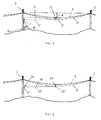
- line 3 can be elongated to assume a lower curve with a larger sag than the indicated sag H, in consequence of the load to which the line is subjected, in particular electric load in the form of increased current which leads to a higher temperature and thus an elongation of the line.
- a laser unit 5 which emits a laser beam 6 when a current of sufficient amplitude flows in the line.
- laser unit 5 can with great advantage be energized from the line 3 in which it is suspended.
- Laser beam 6 is directed towards one (1) of the masts in which line 3 is suspended.
- the beam 6 is shaped so that for usually occuring excursions of line 3 there will always be an illuminated line or arch transversally of a given portion of mast 1. This has to do with the cross-sectional shape of the laser beam 6, which is to be explained more closely below with reference to Fig. 6.
- the illuminated linear spot on mast 1 will move downwards.
- the relationsip between this movement and the temperature change in the line may be calculated by means of known formula or existing calculation programs. If a region of the masts is provided with a scale according to such calculations, the average temperature of line 3 in the span concerned can be read out. More important (and more useful) it is however to be able to automatically record when a predefined critical temperature is obtained (e.g. 80-90°C).
- This situation can be considered to be represented by the dashed line 3', where the laser unit position 5' implies the propagation of laser beam 6' at a lower level than laser beam 6 in the initial position.
- a sensor 7 adapted to receive laser beam 6'.
- a signal indicating the condition occuring can be provided in a manner known per se.
- the signal is transferred either to an operation central with operators or a remote control system gives a direct automatic command to the effect that a switch at the end of line 3 is opened before a dangerous situation can arise. If an alert is desired at more than one temperature level, this can easily be implemented by mounting a sensor for each level at the point on mast 1 corresponding to the temperatures for which an alert is desired.
- another such sensor being located at a lower height than sensor 7.
- One or more sensors 7, 7A on mast 1 are connected to a cable 9 as shown, for transferring the output signal of the sensors to a remote operational or monitoring station.
- these output signals are in the form of laser light derived directly from the laser beam 6' received by the sensor 7 concerned, so that this sensor can be of a simple design without means for converting received laser light to electrical signals.
- the cable 9 is a fiberoptic cable.
- Fig. 1 shows a control box 10 being mounted on mast 1 and being in actual practice usually required in a total installation of the monitoring apparatus, whereby control box 10 can also normally be connected to cable 9, possibly separate electric conductors in a fiberoptic cable.
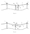
- a unit 15 emitting a laser beam 16 is here mounted on one (1) of the masts in the span concerned.
- a reflector 13 which can direct laser beam 16' to a sensor 17 on the same mast 1 which carries laser unit 15.
- the beam 16 must be so aligned that when line 3 has a sag corresponding to the critical temperature for the line, reflector 13' breaks into the beam and directs it to sensor 17 which converts the light into a signal being transferred in the same manner as in alternative 1.
- a laser unit 25 is mounted on a separate mast 21 laterally of the power line 1, 2, 3 at a predetermined distance from line 3.
- a laser beam 26 is directed transversally of the line at the level corresponding to the sag of the line at the critical temperature.
- line 3' possibly a reflector mounted thereon
- sensor 27 on a separate mast 22 at the opposite side. Transfer of the signal will be implemented in the same way as for alternatives 1 and 2.
- the output signal from sensor 27 in this alternative will be due to disappearance of an incomming laser beam 26 to the sensor.
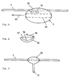
- Fig. 5 shows somewhat more in detail the laser unit 5 supported by line 3, corresponding to the alternative of fig. 1.
- the unit has a much rounded outer shape as represented by a casing 35 in fig. 5.
- the casing can for example be shaped substantially as an ellipsoide, having attachment members for example in the form of a clamp device at the upper part, for mounting on line 3.
- a screen device for protecting components in the laser unit against electric and possibly magnetic fields surrounding line 3 during operation.
- the actual laser component can be located inside the screen 32.
- arrow 45 there is indicated a laser beam being emitted by the laser unit.
- laser unit 5 can have its power supply from line 3 when this carries a current, and for this purpose there is shown at 31 means for this coupling to line 3, i.e. preferably an inductive coupling so as to derive necessary power for the laser unit from line 3 itself.
- Fig 6. illustrates certain geometrical relationships in connection with the situation where line 3 can have lateral excursions, which in particular will be due to transverse wind influence. These geometrical relationships apply both in alternative 1 as illustrated in fig. 1, and in alternative 2 as illustrated in fig. 2.
- laser unit 5 will be swung out together with line 3, and this in the principle along the arc of a circle with the sag H as a radius and with the centre located on the straight line between the suspension points for the power line at the two masts 1 and 2.
- laser beam 6 has a cross section with a certain extension laterally, namely most favourably an arcuate shape as illustrated in fig. 6.
- the arcuate shape is shown therein with a lower or outer arc contour 55 and an inner arc 56 which over a suffisiently large angular range form main borders of the laser beam cross section.
- the radius 3R shown for this arcuate cross section thus shall correspond substantially to the sag H concerned, i.e. when the cross section of the laser beam is considered in the region of mast 1.
- this lower bordering contour 55 of the beam cross section which has a decisive significance for the purpose of detecting a critical sag corresponding to line curve 3' in fig. 1.
- the inner or upper border of the laser beam geometry or cross sectional shape can for example be as shown with a dotted line 57 instead of the arc 56.
- fig. 7 shows how the reflector 13 with advantage can have a rigid attachment to line 3, whereby the attachment member 65 for reflector 13 has a certain extension in the longitudional direction of line 3 for clamping thereof along such a length.
- attachment member 65 has a well rounded shape, this being for the same reason as the casing 35 for laser unit 5 in fig. 5 is rounded.
- the reflector is shown from the side, but it will be realized that the reflecting surface can be shaped according to the advantagous geometry being explained above in connection with fig. 6.
- the arcuate shape, in particular as represented by contoure 55 in fig. 6, will additionally contribute to avoiding undesired potential concentrations at reflector 13.
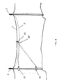
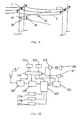
- a transmitter unit 85 for electromagnetic waves for electromagnetic waves, possibly acoustic waves, which can well be ultrasound waves.
- two receivers or sensors 87 and 88 on mast 1 are adapted to receive the emission from unit 85 and in cooperation to determine a time difference between waves received by the respective receivers 87 and 88.
- the height spacing between these two receivers 87 and 88 on mast 1 is a known magnitude, and based on principles being known per se it is thereby possible in a sufficiently accurate manner to determine the position of transmitter unit 85.
- the transmitter unit When the sag is changed, for example to the position of the line being indicated at 3', the transmitter unit will assume another position 85', which leads to a corresponding change in the time difference at receivers 87 and 88.
- the resulting output signal which represents the position or height change of transmitter unit 85, is then delivered to a measuring station or the like for further prosessing and possible action. It is obvious that a fully analogous manner of operation can be based on the emission of ultrasound waves instead of electromagnetic waves from transmitter unit 85. Evidently in such case receiver sensors 87 and 88 must be adapted to detect the sound waves.
- Transmitter unit 85 can emit a continuous wave signal and the time difference referred to above can be determined from the phase relationships at receiver sensors 87 and 88. Position determination, i.e. the sag can also be determined by means of known methods on the basis of a pulse signal from transmitter unit 85.
- a power transmission line with 3 conductors (phases), of which one is denoted 3, as in the previously described embodiments.
- For the line span 3 there is also shown masts 1 and 2.
- a video camera 97 having a field of view 90 so directed that preferably a middle portion of line 3 is located within the field of view.
- This portion of line 3 is provided with an object 93 adapted to be imaged by camera 97.
- the object or figure 93 should have a well defined geometrical shape being suitable for a secure and reliable detection by means of camera 97, which here consitutes a sensor device.
- An electronics unit 99 is also shown on mast 1 in association with camera 97.
- Images being recorded by the camera will in a manner known per se be processed digitally by using a suitable image processing algorithm, in order to search for the particular geometrical figure in the image.
- the height of the line, i.e. also the sag can then be calculated from the position of the figure in the image concerned.
- Digital video cameras 97 which can be employed here, typically will have a resolution of 512 x 582 points, and if there is chosen a lense giving a field of view of 20 x 22,7 meters, there will be obtained a minimum resolution of 4 cm.
- the geometrical figure to be suspended on line 3 therefore should have a lateral dimension of minimum 40 cm so as to be visible for the camera in a way making it possible to detect the figure or object.
- the accuracy of the measurement according to this camera-based embodiment is expected to be +/- 10 - 20 cm, which depends on the field of view and the lense optics in camera 97.
- Necessary processing or image treatment based on the output signals from video camera 97 in fig. 9, can take place in a unit according to the block diagram in fig. 10.
- the components here can be comprised in part or completely by the electronics unit 99 in fig. 9.
- Camera 97 there can for example be employed a CCD camera.
- This delivers digital output signals to an image storing device (frame grabber) 101 in a manner previously known, as a first step of the processing.
- Block 103 represents a suitably programmed computer, which can well be built on one circuit board, for cooperation with image store 101 and other components in the system, as will be seen form the block diagram in fig 10.
- Computer 103 can be considered to provide for the central control of the whole image processing unit and possibly also camera 97 itself.
- the program for computer 103 can be based on available program modules being linked together. There is here the question of processing or image treating algorithms, inter alia for pattern recognition, being per se known or obvious to experts in the field.
- Information being the result of the processing can be transferred via modem 105 and a radio transmitter 107 for example to an operation central or the like for the electrical power distribution.
- Pure still images for camera 97 - image store 101 may be transferred on a low speed channel over radio.
- fig. 10 shows sensors 115A-C for other types of measuring magnitues than the sag, which can also be connected to computer 103 for transferring corresponding information signals over the same channel (modem 105 - radio 107).
- the power supply in the block diagram comprises a central current supply unit 110, a battery 111, energy supply (external) 112, and a particular current supply circuit 113 for a light projector or flash lamp 100.
- Lamp 100 is not shown in fig. 9, since camera 97 in the principle may be able to operate satisfactorily only by means of existing ambient light, in particular daylight.
- a particular form of video camera which in some instances can be advantageous in the practical use of the invention, is a so-called line camera.
- the line cameras provide for imaging in the principle along a line instead of being over an image plane.
- This form of camera requires a light source to be imaged, preferably a laser unit, i.e. a form of unit or component being already referred to above.
- a laser unit i.e. a form of unit or component being already referred to above.
- the fundamental arrangement shown in fig 1 can very well be used in the case of a line camera solution as mentioned here. In such case it is not decisive that the beam 6 from laser unit 5 constitutes a "line of sight".
- a line camera with simultaneous use of cylinder optics having in the principle a vertical axis opens up for an extended detection range.
- a known maner cylinder optics will concentrate all points in a sector into a line.
- This solution involves the possibility of a more precise detection of a varying sag, since the point by which the light source or the laser is imaged, can be used as a basis for taking advantage of the difference in intensity.
- This embodiment will give a continuous measurement of sag within a sector.
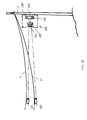
- Fig. 11 in a schematic and simplified way shows an example of an embodiment based on a line camera.
- a line camera generally denoted 129 is suspended for monitoring a line 3, whereby only approximately one half of the line span is shown.
- a transmitter unit 125 in the form of a light source, in particular a laser, which is located in the field of view of line camera 129.
- the power line is shown in another position 3' where the sag has increased, whereby the laser unit has been displaced correspondingly downwards to the position 125'. From the respective positions of laser unit 125 it is indicated with different dot-dash lines how the beam propagation is directed into camera 129.
- this camera can comprise more or less usual objective optics 131 and cylinder optics 132 as mentioned above.
- Imaging takes place in a field or plane 133 which can be relatively narrow and has a certain extension in vertical direction.
- a light point representing laser unit 125 in the upper position will be imaged for example as a point 135 in the imaging plane 133, whereas the light point from the laser unit in the position 125', will be imaged at 135' in the imaging plane 133.
- suitable detector elements associated with imaging plane 133 it will thus be possible to carry out the continuous measurement of the sag of line 3.
- the transmitter units, reflectors or imaging objects need not be located at the middle of a line span, but can be displced from the middle portion depending on the local conditions, such as terrain formations, buildings and so forth in the neighbourhood of the power transmission line.
- Particular situations as for example fjord spans or power lines installed at other inaccessible places, may also lead to modifications of the total arrangement of sensor device and possibly the transmitter unit.
- signal processing as in particular discussed in connection with the camera embodiment, there can also in addition to processing as mentioned, be employed additional and other forms of signal processing, such as filtering, correlation techniques based on pulse emission from the transmitter units and so forth.
Landscapes
- Physics & Mathematics (AREA)
- General Physics & Mathematics (AREA)
- Electric Cable Installation (AREA)
- Length Measuring Devices By Optical Means (AREA)
- Testing Of Short-Circuits, Discontinuities, Leakage, Or Incorrect Line Connections (AREA)
- Investigating Or Analyzing Materials Using Thermal Means (AREA)
- Remote Monitoring And Control Of Power-Distribution Networks (AREA)
- Locating Faults (AREA)
- Investigating Or Analyzing Materials By The Use Of Magnetic Means (AREA)
Applications Claiming Priority (3)
| Application Number | Priority Date | Filing Date | Title |
|---|---|---|---|
| NO942358A NO942358L (no) | 1994-06-20 | 1994-06-20 | Anordning for overvåkning av elektriske luftledninger |
| NO942358 | 1994-06-20 | ||
| PCT/NO1995/000106 WO1995035478A1 (en) | 1994-06-20 | 1995-06-19 | Apparatus for monitoring overhead electric lines |
Publications (2)
| Publication Number | Publication Date |
|---|---|
| EP0766809A1 EP0766809A1 (en) | 1997-04-09 |
| EP0766809B1 true EP0766809B1 (en) | 1999-08-25 |
Family
ID=19897202
Family Applications (1)
| Application Number | Title | Priority Date | Filing Date |
|---|---|---|---|
| EP95923604A Expired - Lifetime EP0766809B1 (en) | 1994-06-20 | 1995-06-19 | Apparatus for monitoring overhead electric lines |
Country Status (9)
| Country | Link |
|---|---|
| EP (1) | EP0766809B1 (da) |
| JP (1) | JPH10502730A (da) |
| AT (1) | ATE183823T1 (da) |
| AU (1) | AU696185B2 (da) |
| CA (1) | CA2191889A1 (da) |
| DE (1) | DE69511697T2 (da) |
| DK (1) | DK0766809T3 (da) |
| NO (1) | NO942358L (da) |
| WO (1) | WO1995035478A1 (da) |
Cited By (2)
| Publication number | Priority date | Publication date | Assignee | Title |
|---|---|---|---|---|
| DE10345508A1 (de) * | 2003-09-30 | 2005-10-20 | Siemens Ag | Verfahren und Vorrichtung zum Monitoring von Bahn-Fahrdrahtleitungen |
| CN110715608A (zh) * | 2018-07-13 | 2020-01-21 | 中惠创智无线供电技术有限公司 | 轨道式无线供电系统及用于线缆的运行设备 |
Families Citing this family (21)
| Publication number | Priority date | Publication date | Assignee | Title |
|---|---|---|---|---|
| DE19718186C1 (de) * | 1997-04-30 | 1998-09-03 | Rwe Energie Ag | Verfahren für eine Zustandsüberwachung von Hochspannungs-Freileitungen |
| DE19936448A1 (de) * | 1999-08-03 | 2001-03-15 | Siemens Ag | Bildaufnahme- und Auswertesystem |
| NO318809B1 (no) | 2002-10-07 | 2005-05-09 | Protura As | Anordning for overvakning av en elektrisk luftstrekk-ledning |
| US7575371B1 (en) * | 2004-11-11 | 2009-08-18 | Fieldmetrics, Inc | Temperature sensor and extensometer |
| DE102006031487B4 (de) * | 2006-07-06 | 2011-06-16 | Institut für Bahntechnik GmbH | Verfahren zur Fahrdrahtanhubmessung |
| US8386198B2 (en) | 2008-11-06 | 2013-02-26 | Southwire Company | Real-time power line rating |
| DE102009020267A1 (de) * | 2009-05-07 | 2010-11-11 | Siemens Aktiengesellschaft | Verfahren zum Erkennen einer Zustandsänderung einer Oberleitungsanlage |
| US10205307B2 (en) | 2010-03-23 | 2019-02-12 | Southwire Company, Llc | Power line maintenance monitoring |
| CN102155935B (zh) * | 2011-03-08 | 2012-09-05 | 四川电力科学研究院 | 一种输电线路分裂导线覆冰翻转角度检测装置的检测方法 |
| DE102014208734A1 (de) * | 2014-05-09 | 2015-11-12 | DB Systemtechnik GmbH | Verfahren zur Messung des Anhubs elektrischer Fahrleitungen auf Fahrwegen des schienengebundenen Verkehrs |
| CN104729412A (zh) * | 2015-03-16 | 2015-06-24 | 华南理工大学 | 一种测量架空输电线路弧垂的方法 |
| CN105180867B (zh) * | 2015-06-09 | 2018-05-08 | 四川汇源光通信有限公司 | 基于倾角差分法的导线弧垂测量系统与方法 |
| CN104897089A (zh) * | 2015-06-18 | 2015-09-09 | 四川汇源光通信有限公司 | 输电线动弯应变量测量系统及方法 |
| CN105021133B (zh) * | 2015-07-21 | 2017-10-03 | 鞍钢集团工程技术有限公司 | 一种输电线挠度的测量方法 |
| CN105928475A (zh) * | 2016-05-04 | 2016-09-07 | 国网浙江杭州市余杭区供电公司 | 一种电力光缆高度监测设备及系统 |
| CN109099870A (zh) * | 2018-07-16 | 2018-12-28 | 国网辽宁省电力有限公司盘锦供电公司 | 一种弧垂测量装置 |
| CN110906871B (zh) * | 2019-11-29 | 2021-08-03 | 河南送变电建设有限公司 | 一种通过档侧弧垂观测调整导线的方法 |
| DE102020205071A1 (de) | 2020-04-22 | 2021-10-28 | Fraunhofer-Gesellschaft zur Förderung der angewandten Forschung eingetragener Verein | Vorrichtung zur Erfassung der Relativlage zwischen einem an einer Tragstruktur angebrachten Befestigungsanker und einem endseitig am Befestigungsanker angebrachten, gespannten Tragseil |
| CN112833762B (zh) * | 2021-01-08 | 2021-11-09 | 安徽送变电工程有限公司 | 弧垂测量算法、系统、装置及存储介质 |
| CN114396860B (zh) * | 2021-12-06 | 2023-05-02 | 清华大学 | 基于地线电磁信号的输电线路增容时弧垂监测方法和装置 |
| CN117906544A (zh) * | 2024-03-19 | 2024-04-19 | 四川省电子产品监督检验所 | 一种用于电力通信光缆的弧垂状态检测装置及方法 |
Family Cites Families (3)
| Publication number | Priority date | Publication date | Assignee | Title |
|---|---|---|---|---|
| US5140257A (en) * | 1984-06-22 | 1992-08-18 | Davis Murray W | System for rating electric power transmission lines and equipment |
| DE3825415A1 (de) * | 1988-07-27 | 1990-04-12 | Voith Gmbh J M | Einrichtung zur messung der durchbiegung langgesetreckter bauteile |
| US5235861A (en) * | 1991-05-03 | 1993-08-17 | Seppa Tapani O | Power transmission line monitoring system |
-
1994
- 1994-06-20 NO NO942358A patent/NO942358L/no unknown
-
1995
- 1995-06-19 WO PCT/NO1995/000106 patent/WO1995035478A1/en active IP Right Grant
- 1995-06-19 AT AT95923604T patent/ATE183823T1/de not_active IP Right Cessation
- 1995-06-19 AU AU28097/95A patent/AU696185B2/en not_active Ceased
- 1995-06-19 CA CA002191889A patent/CA2191889A1/en not_active Abandoned
- 1995-06-19 EP EP95923604A patent/EP0766809B1/en not_active Expired - Lifetime
- 1995-06-19 JP JP8501980A patent/JPH10502730A/ja active Pending
- 1995-06-19 DE DE69511697T patent/DE69511697T2/de not_active Expired - Fee Related
- 1995-06-19 DK DK95923604T patent/DK0766809T3/da active
Cited By (3)
| Publication number | Priority date | Publication date | Assignee | Title |
|---|---|---|---|---|
| DE10345508A1 (de) * | 2003-09-30 | 2005-10-20 | Siemens Ag | Verfahren und Vorrichtung zum Monitoring von Bahn-Fahrdrahtleitungen |
| DE10345508B4 (de) * | 2003-09-30 | 2006-03-16 | Siemens Ag | Verfahren und Vorrichtung zum Monitoring von Bahn-Fahrdrahtleitungen |
| CN110715608A (zh) * | 2018-07-13 | 2020-01-21 | 中惠创智无线供电技术有限公司 | 轨道式无线供电系统及用于线缆的运行设备 |
Also Published As
| Publication number | Publication date |
|---|---|
| DE69511697D1 (de) | 1999-09-30 |
| DK0766809T3 (da) | 2000-02-21 |
| JPH10502730A (ja) | 1998-03-10 |
| CA2191889A1 (en) | 1995-12-28 |
| AU696185B2 (en) | 1998-09-03 |
| ATE183823T1 (de) | 1999-09-15 |
| EP0766809A1 (en) | 1997-04-09 |
| NO942358L (no) | 1995-12-21 |
| NO942358D0 (da) | 1994-06-20 |
| WO1995035478A1 (en) | 1995-12-28 |
| DE69511697T2 (de) | 2000-05-04 |
| AU2809795A (en) | 1996-01-15 |
Similar Documents
| Publication | Publication Date | Title |
|---|---|---|
| EP0766809B1 (en) | Apparatus for monitoring overhead electric lines | |
| US6417783B1 (en) | Motor vehicle detector | |
| US6784983B1 (en) | System for monitoring cables | |
| CN102264171A (zh) | 远距离感应路灯系统 | |
| CN108919233A (zh) | 一种大气颗粒物层析仪 | |
| KR100310518B1 (ko) | 크레인에서 물체 진자 운동 및/또는 회전을 2차원 측정하기 위한 장치 및 방법 | |
| RU2689564C1 (ru) | Способ измерения параметров контактного провода электротранспорта и устройство для его реализации | |
| JPH0692883B2 (ja) | トロリ線摩耗測定装置 | |
| JP3530259B2 (ja) | トロリ線監視装置の光源ユニット | |
| ES2228364T3 (es) | Sistema de toma y de evaluacion de imagenes. | |
| JPH09159414A (ja) | 携帯型トロリ線摩耗測定装置 | |
| JPH08178624A (ja) | トロリ線の高さ・偏位測定装置 | |
| KR100894977B1 (ko) | 양안시차를 이용한 수위 측정 장치 | |
| CN213423096U (zh) | 一种基于多种监测手段的航标灯器智能巡检设备 | |
| CN215953877U (zh) | 一种一体化断线报警自动监测站 | |
| CN218211210U (zh) | 一种大坝变形监测系统 | |
| JP3244265U (ja) | 光学遠隔測定に基づくワイヤ損傷評価装置 | |
| CN218035120U (zh) | 一种混凝土索塔运营状态预警监测系统 | |
| Fletcher | Automatic measurement of the position of the overhead contact wire | |
| JPH06324104A (ja) | 電力線用碍子の破損検出方法及び装置 | |
| RU2138410C1 (ru) | Устройство для измерения износа контактного провода | |
| CN118149760A (zh) | 一种船舶净空高度检测系统 | |
| JP2020178447A (ja) | 電力供給システム | |
| RU2098904C1 (ru) | Устройство для контроля массы гололедных отложений на высоковольтных проводах воздушных линий электропередач | |
| CN109751956A (zh) | 一种悬挂缆线测量方法及装置 |
Legal Events
| Date | Code | Title | Description |
|---|---|---|---|
| PUAI | Public reference made under article 153(3) epc to a published international application that has entered the european phase |
Free format text: ORIGINAL CODE: 0009012 |
|
| 17P | Request for examination filed |
Effective date: 19961205 |
|
| AK | Designated contracting states |
Kind code of ref document: A1 Designated state(s): AT BE CH DE DK ES FR GB GR IE IT LI LU MC NL PT SE |
|
| 17Q | First examination report despatched |
Effective date: 19980211 |
|
| GRAG | Despatch of communication of intention to grant |
Free format text: ORIGINAL CODE: EPIDOS AGRA |
|
| GRAG | Despatch of communication of intention to grant |
Free format text: ORIGINAL CODE: EPIDOS AGRA |
|
| GRAH | Despatch of communication of intention to grant a patent |
Free format text: ORIGINAL CODE: EPIDOS IGRA |
|
| GRAH | Despatch of communication of intention to grant a patent |
Free format text: ORIGINAL CODE: EPIDOS IGRA |
|
| GRAA | (expected) grant |
Free format text: ORIGINAL CODE: 0009210 |
|
| AK | Designated contracting states |
Kind code of ref document: B1 Designated state(s): AT BE CH DE DK ES FR GB GR IE IT LI LU MC NL PT SE |
|
| PG25 | Lapsed in a contracting state [announced via postgrant information from national office to epo] |
Ref country code: NL Free format text: LAPSE BECAUSE OF FAILURE TO SUBMIT A TRANSLATION OF THE DESCRIPTION OR TO PAY THE FEE WITHIN THE PRESCRIBED TIME-LIMIT Effective date: 19990825 Ref country code: IT Free format text: LAPSE BECAUSE OF FAILURE TO SUBMIT A TRANSLATION OF THE DESCRIPTION OR TO PAY THE FEE WITHIN THE PRESCRIBED TIME-LIMIT;WARNING: LAPSES OF ITALIAN PATENTS WITH EFFECTIVE DATE BEFORE 2007 MAY HAVE OCCURRED AT ANY TIME BEFORE 2007. THE CORRECT EFFECTIVE DATE MAY BE DIFFERENT FROM THE ONE RECORDED. Effective date: 19990825 Ref country code: GR Free format text: LAPSE BECAUSE OF NON-PAYMENT OF DUE FEES Effective date: 19990825 Ref country code: ES Free format text: THE PATENT HAS BEEN ANNULLED BY A DECISION OF A NATIONAL AUTHORITY Effective date: 19990825 |
|
| REF | Corresponds to: |
Ref document number: 183823 Country of ref document: AT Date of ref document: 19990915 Kind code of ref document: T |
|
| REG | Reference to a national code |
Ref country code: CH Ref legal event code: EP |
|
| REF | Corresponds to: |
Ref document number: 69511697 Country of ref document: DE Date of ref document: 19990930 |
|
| REG | Reference to a national code |
Ref country code: IE Ref legal event code: FG4D |
|
| PG25 | Lapsed in a contracting state [announced via postgrant information from national office to epo] |
Ref country code: PT Free format text: LAPSE BECAUSE OF FAILURE TO SUBMIT A TRANSLATION OF THE DESCRIPTION OR TO PAY THE FEE WITHIN THE PRESCRIBED TIME-LIMIT Effective date: 19991125 |
|
| REG | Reference to a national code |
Ref country code: CH Ref legal event code: NV Representative=s name: BOVARD AG PATENTANWAELTE |
|
| ET | Fr: translation filed | ||
| NLV1 | Nl: lapsed or annulled due to failure to fulfill the requirements of art. 29p and 29m of the patents act | ||
| REG | Reference to a national code |
Ref country code: DK Ref legal event code: T3 |
|
| PG25 | Lapsed in a contracting state [announced via postgrant information from national office to epo] |
Ref country code: LU Free format text: LAPSE BECAUSE OF NON-PAYMENT OF DUE FEES Effective date: 20000619 |
|
| PLBE | No opposition filed within time limit |
Free format text: ORIGINAL CODE: 0009261 |
|
| STAA | Information on the status of an ep patent application or granted ep patent |
Free format text: STATUS: NO OPPOSITION FILED WITHIN TIME LIMIT |
|
| PG25 | Lapsed in a contracting state [announced via postgrant information from national office to epo] |
Ref country code: MC Free format text: THE PATENT HAS BEEN ANNULLED BY A DECISION OF A NATIONAL AUTHORITY Effective date: 20000630 |
|
| 26N | No opposition filed | ||
| PGFP | Annual fee paid to national office [announced via postgrant information from national office to epo] |
Ref country code: DK Payment date: 20010528 Year of fee payment: 7 |
|
| PGFP | Annual fee paid to national office [announced via postgrant information from national office to epo] |
Ref country code: SE Payment date: 20010529 Year of fee payment: 7 |
|
| PGFP | Annual fee paid to national office [announced via postgrant information from national office to epo] |
Ref country code: IE Payment date: 20010605 Year of fee payment: 7 Ref country code: GB Payment date: 20010605 Year of fee payment: 7 |
|
| PGFP | Annual fee paid to national office [announced via postgrant information from national office to epo] |
Ref country code: FR Payment date: 20010606 Year of fee payment: 7 |
|
| PGFP | Annual fee paid to national office [announced via postgrant information from national office to epo] |
Ref country code: BE Payment date: 20010608 Year of fee payment: 7 |
|
| PGFP | Annual fee paid to national office [announced via postgrant information from national office to epo] |
Ref country code: CH Payment date: 20010612 Year of fee payment: 7 |
|
| PGFP | Annual fee paid to national office [announced via postgrant information from national office to epo] |
Ref country code: AT Payment date: 20010619 Year of fee payment: 7 |
|
| PGFP | Annual fee paid to national office [announced via postgrant information from national office to epo] |
Ref country code: DE Payment date: 20010830 Year of fee payment: 7 |
|
| REG | Reference to a national code |
Ref country code: GB Ref legal event code: IF02 |
|
| PG25 | Lapsed in a contracting state [announced via postgrant information from national office to epo] |
Ref country code: IE Free format text: LAPSE BECAUSE OF NON-PAYMENT OF DUE FEES Effective date: 20020619 Ref country code: GB Free format text: LAPSE BECAUSE OF NON-PAYMENT OF DUE FEES Effective date: 20020619 Ref country code: AT Free format text: LAPSE BECAUSE OF NON-PAYMENT OF DUE FEES Effective date: 20020619 |
|
| PG25 | Lapsed in a contracting state [announced via postgrant information from national office to epo] |
Ref country code: SE Free format text: LAPSE BECAUSE OF NON-PAYMENT OF DUE FEES Effective date: 20020620 |
|
| PG25 | Lapsed in a contracting state [announced via postgrant information from national office to epo] |
Ref country code: LI Free format text: LAPSE BECAUSE OF NON-PAYMENT OF DUE FEES Effective date: 20020630 Ref country code: CH Free format text: LAPSE BECAUSE OF NON-PAYMENT OF DUE FEES Effective date: 20020630 Ref country code: BE Free format text: LAPSE BECAUSE OF NON-PAYMENT OF DUE FEES Effective date: 20020630 |
|
| PG25 | Lapsed in a contracting state [announced via postgrant information from national office to epo] |
Ref country code: DK Free format text: LAPSE BECAUSE OF NON-PAYMENT OF DUE FEES Effective date: 20020731 |
|
| BERE | Be: lapsed |
Owner name: *HAFSLUND ASA Effective date: 20020630 |
|
| PG25 | Lapsed in a contracting state [announced via postgrant information from national office to epo] |
Ref country code: DE Free format text: LAPSE BECAUSE OF NON-PAYMENT OF DUE FEES Effective date: 20030101 |
|
| EUG | Se: european patent has lapsed | ||
| GBPC | Gb: european patent ceased through non-payment of renewal fee |
Effective date: 20020619 |
|
| REG | Reference to a national code |
Ref country code: DK Ref legal event code: EBP |
|
| REG | Reference to a national code |
Ref country code: CH Ref legal event code: PL |
|
| PG25 | Lapsed in a contracting state [announced via postgrant information from national office to epo] |
Ref country code: FR Free format text: LAPSE BECAUSE OF NON-PAYMENT OF DUE FEES Effective date: 20030228 |
|
| REG | Reference to a national code |
Ref country code: IE Ref legal event code: MM4A |
|
| REG | Reference to a national code |
Ref country code: FR Ref legal event code: ST |