EP0765690A1 - Abgabevorrichtung - Google Patents
Abgabevorrichtung Download PDFInfo
- Publication number
- EP0765690A1 EP0765690A1 EP96306766A EP96306766A EP0765690A1 EP 0765690 A1 EP0765690 A1 EP 0765690A1 EP 96306766 A EP96306766 A EP 96306766A EP 96306766 A EP96306766 A EP 96306766A EP 0765690 A1 EP0765690 A1 EP 0765690A1
- Authority
- EP
- European Patent Office
- Prior art keywords
- container
- feed tube
- base
- foot
- dispensing system
- Prior art date
- Legal status (The legal status is an assumption and is not a legal conclusion. Google has not performed a legal analysis and makes no representation as to the accuracy of the status listed.)
- Granted
Links
Images

Classifications
-
- B—PERFORMING OPERATIONS; TRANSPORTING
- B05—SPRAYING OR ATOMISING IN GENERAL; APPLYING FLUENT MATERIALS TO SURFACES, IN GENERAL
- B05B—SPRAYING APPARATUS; ATOMISING APPARATUS; NOZZLES
- B05B11/00—Single-unit hand-held apparatus in which flow of contents is produced by the muscular force of the operator at the moment of use
- B05B11/01—Single-unit hand-held apparatus in which flow of contents is produced by the muscular force of the operator at the moment of use characterised by the means producing the flow
- B05B11/10—Pump arrangements for transferring the contents from the container to a pump chamber by a sucking effect and forcing the contents out through the dispensing nozzle
- B05B11/1042—Components or details
- B05B11/1073—Springs
- B05B11/1074—Springs located outside pump chambers
-
- B—PERFORMING OPERATIONS; TRANSPORTING
- B05—SPRAYING OR ATOMISING IN GENERAL; APPLYING FLUENT MATERIALS TO SURFACES, IN GENERAL
- B05B—SPRAYING APPARATUS; ATOMISING APPARATUS; NOZZLES
- B05B15/00—Details of spraying plant or spraying apparatus not otherwise provided for; Accessories
- B05B15/30—Dip tubes
-
- B—PERFORMING OPERATIONS; TRANSPORTING
- B05—SPRAYING OR ATOMISING IN GENERAL; APPLYING FLUENT MATERIALS TO SURFACES, IN GENERAL
- B05B—SPRAYING APPARATUS; ATOMISING APPARATUS; NOZZLES
- B05B11/00—Single-unit hand-held apparatus in which flow of contents is produced by the muscular force of the operator at the moment of use
- B05B11/01—Single-unit hand-held apparatus in which flow of contents is produced by the muscular force of the operator at the moment of use characterised by the means producing the flow
- B05B11/02—Membranes or pistons acting on the contents inside the container, e.g. follower pistons
- B05B11/028—Pistons separating the content remaining in the container from the atmospheric air to compensate underpressure inside the container
- B05B11/029—Pistons separating the content remaining in the container from the atmospheric air to compensate underpressure inside the container located on top of the remaining content
-
- B—PERFORMING OPERATIONS; TRANSPORTING
- B05—SPRAYING OR ATOMISING IN GENERAL; APPLYING FLUENT MATERIALS TO SURFACES, IN GENERAL
- B05B—SPRAYING APPARATUS; ATOMISING APPARATUS; NOZZLES
- B05B11/00—Single-unit hand-held apparatus in which flow of contents is produced by the muscular force of the operator at the moment of use
- B05B11/01—Single-unit hand-held apparatus in which flow of contents is produced by the muscular force of the operator at the moment of use characterised by the means producing the flow
- B05B11/10—Pump arrangements for transferring the contents from the container to a pump chamber by a sucking effect and forcing the contents out through the dispensing nozzle
- B05B11/1001—Piston pumps
Definitions
- This invention relates to dispensing systems in which a pump dispenses flowable material from a container, the material being fed to the pump through a feed tube extending down into a container.
- the system generally comprises a container having a base and a side wall, to hold flowable material for dispensing, a dispenser pump mounted at the top of the container, a feed tube extending in the container down from the dispenser pump intake to the container base to convey product from the container into the pump, and a follower plate fitting axially slidably around the feed tube and extending out to the container's side wall, to follow the surface of the product down the container as dispensing proceeds.
- the interlock engagement may take any suitable form provided that it prevents lateral movement, since even a small deviation can hinder the follower plate. Typically this requires a fitting engagement, with laterally-directed parts of the tube fitting against laterally-directed parts of the base.
- the connection may however allow relative axial movement and/or rotational movement around the tube axis, particularly since these are usually needed for installing the tube in the container.
- one or both of the tube foot and container base may provide tapered guide surfaces to lead the other component into fitting engagement with the fitting surfaces on installation.
- the preferred version uses one or more upward projections of the container base to engage and fit inside or outside the tube foot's periphery, which is typically annular. A standard plain feed tube may then be used, only the container needing modification.
- the feed tube must of course provide one or more product intake openings, and these are generally down at the container base to ensure full product clearance.
- the foot/base engagement construction needs to provide clearance for this. This may be achieved by a circumferentially segmented engagement, e.g circumferentially-spaced interlock segments projecting up from the container base. The narrower the segments, the less the criticality of rotational alignment between foot and base. So, a preferred construction uses a set of circumferentially-spaced, circumferentially-localised lugs or fins whose radially-directed edges make the interlock engagement.
- Radially-directed fins can be provided on the base to engage either outside or inside the tube foot.
- a simple and strong construction has a single central upward projection with radially-directed fins in cruciform or stellate arrangement. This projection can have a convergent top to give the guiding referred to above.
- the engaging parts of the base and tube foot are preferably complementarily shaped.
- the components can be made by standard plastics moulding techniques.
- the other components of the arrangement may be conventional.
- the follower plate can be a flat plate with upwardly-flared sealing lips at its inner and outer peripheries, to seal against the feed tube and container wall respectively.
- seal or follower plate may be used.
- the container is typically but not exclusively cylindrical.
- the feed tube may be central.
- the pump may be of any suitable type.
- One preferred form has a pump body which seats into a cap to cover the container opening.
- the pump chamber may extend down into the container.
- the feed tube may be provided by a tubular component which sits onto a spigot at the pump body inlet, or may extend up around the pump chamber as a housing for or part of the pump.
- the pump is typically plunger-operated, with a fixed or movable dispensing nozzle mounted above the container, but this is just one preferred option. Indeed, a pump could be separately mounted provided that its feed from the container top originates with the feed tube.
- aspects put forward for protection here include not only the dispensing system as a whole but also the combination of container and feed tube (with or without the follower plate) adapted to engage one another as aforesaid, and also a container whose base is provided with one or more upstanding engagement projections as described herein.
- a cylindrical container 1 has a cylindrical side wall 12 and a flat base 11.
- the container is a one-piece plastics moulding e.g of polypropylene.
- a pump 2 is mounted over the top opening of the container 1, by means of a cover cap 13.
- the cap 13 snap fits onto the container 1 by means of a downward skirt 131 having an annular recess 132 which snaps onto a annular bead 122 on the outside of the container wall 12.
- the body of the pump 2 is mounted through a hole 133 in the centre of the cap 13 by a screw or snap fit between a lower body sleeve or cylinder 22, which extends generally below the cap 13 but has a screw or snap collar projecting up through the hole 133, and an upper body sleeve 21 which screws or snaps down around that collar to trap the cap and hold the body in position.
- the lower body sleeve 22 defines a cylindrical pump chamber which a piston 24 is vertically reciprocable together with a piston rod 25 and a plunger head 26 fixed to the top of the piston rod 25.
- the piston is hollow, communicating with a discharge channel 251 extending up through the piston rod 25 to an outlet valve 28 in the head and thence to a transverse discharge spout 261 which moves up and down with the head.
- the upper body sleeve 21 has an inward shelf 211 with a central hole through which the piston rod 25 slides; the shelf 211 provides both an upper limit for the travel of the piston 24 and a lower abutment for a pump spring 29 which tends to urge the head 26 to its upper position.
- the bottom of the lower body sleeve has an axial intake spigot 23 leading to the pump chamber through an inlet valve 27.
- the pump body may be of polypropylene.
- a parallel-sided in this embodiment, cylindrical) stiff feed tube 3 extends from the top to the bottom of the container 1, in line with the pump at its centre.
- the foot 32 of the tube 3 lies on the pump base 11; from here the tube 3 extends up and around the pump intake 23, around the lower pump body sleeve 22 (with a close fit) and has a top flange 311 abutting against a shoulder of the pump body adjacent the top cap 13. The top of the feed tube 3 is thus fixed firmly in position.
- the foot of the feed tube 3 provides circumferentially-spaced openings 322 for the inflow of product 5 from the container. Between the openings 322 portions of the tube foot reach down to support the tube against the container base 11. In this embodiment, three circumferentially-spaced openings 322 are provided.
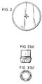
- the foot of the tube with the openings is provided as a separate insert component 321 which defines the openings 322 and also has an upper tubular part 324 which plugs into the foot of the main cylindrical feed tube body 3. This is shown more clearly in Figs 3(a) and (b), which show the insert component separately.
- the opening may be formed directly in the foot of a single tube component.
- the feed tube may be moulded, e.g from polypropylene or high-density polyethylene (HDPE).
- a follower plate 4 is provided to rest on top of the body of product 5 in the container and follow it down the container as dispensing progresses.
- the follower plate comprises a generally flat radial web 43 with an inward annular sealing lip 41 sealing against the feed tube wall and an outer annular sealing lip 42 sealing against the container wall.
- the sealing lips 41,42 are provided at upwardly-flaring tapered portions forming in one piece the with remainder of the follower plate 4. Upwardly-extending seals are desirable so that the main web 43 of the follower plate 4 can reach down to the base 11 of the container.
- the follower plate may be of LDPE.
- a locating projection 14 extends up from the container base 11 through the open foot of the feed tube 3.
- This projection 14 can be moulded in one piece with the container. It extends up into the tube past the openings 322.
- shape as also seen from Fig 2, it consists of a set of radially-projecting axial fins 141, each with an edge whose radially outermost part is an axially-straight fitting portion 143, with above that a tapered guide region 142 slanting in towards the tube axis.
- the fins 141 meet in the middle and there are four of them, so they form a cruciform spike projecting up from the container base.
- the cruciform spike shown is merely one convenient way of achieving the desired effect. It has the advantage of simplicity and strength.
- the use of fins minimises the obstruction to the openings 322, so that no particular rotational or alignment is needed between the tube 3 and protection 14. At the same time the combination of the fins into a single stellate projection gives it greater strength.
- Another possibility is to recess the container floor to receive the tube foot, but this may be more difficult to achieve with thin container walls unless some additional guide projection is provided.
Landscapes
- Closures For Containers (AREA)
- Electrical Discharge Machining, Electrochemical Machining, And Combined Machining (AREA)
- Coating Apparatus (AREA)
- Paper (AREA)
- Air Transport Of Granular Materials (AREA)
- Motor Or Generator Cooling System (AREA)
- Devices For Dispensing Beverages (AREA)
Applications Claiming Priority (2)
| Application Number | Priority Date | Filing Date | Title |
|---|---|---|---|
| GB9519346 | 1995-09-22 | ||
| GBGB9519346.2A GB9519346D0 (en) | 1995-09-22 | 1995-09-22 | Dispensing systems |
Publications (2)
| Publication Number | Publication Date |
|---|---|
| EP0765690A1 true EP0765690A1 (de) | 1997-04-02 |
| EP0765690B1 EP0765690B1 (de) | 2000-03-22 |
Family
ID=10781090
Family Applications (1)
| Application Number | Title | Priority Date | Filing Date |
|---|---|---|---|
| EP96306766A Expired - Lifetime EP0765690B1 (de) | 1995-09-22 | 1996-09-18 | Abgabevorrichtung |
Country Status (7)
| Country | Link |
|---|---|
| US (1) | US6302304B1 (de) |
| EP (1) | EP0765690B1 (de) |
| AT (1) | ATE190870T1 (de) |
| DE (1) | DE69607276T2 (de) |
| DK (1) | DK0765690T3 (de) |
| ES (1) | ES2146360T3 (de) |
| GB (1) | GB9519346D0 (de) |
Cited By (4)
| Publication number | Priority date | Publication date | Assignee | Title |
|---|---|---|---|---|
| EP0899206A1 (de) | 1997-08-26 | 1999-03-03 | The English Glass Company Limited | Abgabesysteme |
| GB2335241A (en) * | 1998-07-13 | 1999-09-15 | English Glass Co Ltd | Dispensing systems |
| DE102005049531A1 (de) * | 2005-04-25 | 2006-10-26 | Rpc Bramlage Gmbh | Spender für flüssige oder pastöse Massen |
| WO2009109370A1 (de) | 2008-03-04 | 2009-09-11 | Ursapharm Arzneimittel Gmbh & Co. Kg | Dosierungsvorrichtung |
Families Citing this family (63)
| Publication number | Priority date | Publication date | Assignee | Title |
|---|---|---|---|---|
| US6048734A (en) | 1995-09-15 | 2000-04-11 | The Regents Of The University Of Michigan | Thermal microvalves in a fluid flow method |
| US7014068B1 (en) * | 1999-08-23 | 2006-03-21 | Ben Z. Cohen | Microdispensing pump |
| DE10108299B4 (de) * | 2000-05-18 | 2011-03-03 | Ophardt Product Kg | Vorrichtung zum Erzeugen und Abgeben von Schaum |
| FR2815675B1 (fr) * | 2000-10-23 | 2003-05-02 | Valois Sa | Pompe de distribution de produit fluide |
| US6692700B2 (en) | 2001-02-14 | 2004-02-17 | Handylab, Inc. | Heat-reduction methods and systems related to microfluidic devices |
| US7323140B2 (en) | 2001-03-28 | 2008-01-29 | Handylab, Inc. | Moving microdroplets in a microfluidic device |
| US8895311B1 (en) | 2001-03-28 | 2014-11-25 | Handylab, Inc. | Methods and systems for control of general purpose microfluidic devices |
| US7829025B2 (en) | 2001-03-28 | 2010-11-09 | Venture Lending & Leasing Iv, Inc. | Systems and methods for thermal actuation of microfluidic devices |
| US6852287B2 (en) | 2001-09-12 | 2005-02-08 | Handylab, Inc. | Microfluidic devices having a reduced number of input and output connections |
| US7010391B2 (en) | 2001-03-28 | 2006-03-07 | Handylab, Inc. | Methods and systems for control of microfluidic devices |
| US6923346B2 (en) * | 2002-11-06 | 2005-08-02 | Continental Afa Dispensing Company | Foaming liquid dispenser |
| US6644516B1 (en) | 2002-11-06 | 2003-11-11 | Continental Afa Dispensing Company | Foaming liquid dispenser |
| US6945435B2 (en) * | 2003-04-17 | 2005-09-20 | Helen Of Troy Limited | User-refillable liquid dispensing container with vacuum actuated piston |
| EP3718635A1 (de) | 2003-07-31 | 2020-10-07 | Handylab, Inc. | Verarbeitung partikelhaltiger proben |
| US6840408B1 (en) | 2003-08-25 | 2005-01-11 | Continental Afa Dispensing Company | Air foam pump with shifting air piston |
| US8852862B2 (en) | 2004-05-03 | 2014-10-07 | Handylab, Inc. | Method for processing polynucleotide-containing samples |
| CA3198754A1 (en) | 2004-05-03 | 2005-11-17 | Handylab, Inc. | A microfluidic device and methods for processing polynucleotide-containing samples |
| US7007827B1 (en) * | 2004-12-01 | 2006-03-07 | Shih-Wei Li | Emulsion dispenser |
| US20070045349A1 (en) * | 2005-08-25 | 2007-03-01 | Continental Afa Dispensing Company | Liquid dispensing pump with shifting liquid piston |
| US7998708B2 (en) * | 2006-03-24 | 2011-08-16 | Handylab, Inc. | Microfluidic system for amplifying and detecting polynucleotides in parallel |
| US8883490B2 (en) | 2006-03-24 | 2014-11-11 | Handylab, Inc. | Fluorescence detector for microfluidic diagnostic system |
| US11806718B2 (en) | 2006-03-24 | 2023-11-07 | Handylab, Inc. | Fluorescence detector for microfluidic diagnostic system |
| EP2001990B1 (de) | 2006-03-24 | 2016-06-29 | Handylab, Inc. | Integriertes system zur verarbeitung von mikrofluidischen proben und verwendungsverfahren |
| US10900066B2 (en) | 2006-03-24 | 2021-01-26 | Handylab, Inc. | Microfluidic system for amplifying and detecting polynucleotides in parallel |
| US8088616B2 (en) | 2006-03-24 | 2012-01-03 | Handylab, Inc. | Heater unit for microfluidic diagnostic system |
| US20060196889A1 (en) * | 2006-04-20 | 2006-09-07 | Masatoshi Masuda | Fluid storage container with piston provided inside |
| WO2008061165A2 (en) | 2006-11-14 | 2008-05-22 | Handylab, Inc. | Microfluidic cartridge and method of making same |
| US8287820B2 (en) | 2007-07-13 | 2012-10-16 | Handylab, Inc. | Automated pipetting apparatus having a combined liquid pump and pipette head system |
| US9186677B2 (en) | 2007-07-13 | 2015-11-17 | Handylab, Inc. | Integrated apparatus for performing nucleic acid extraction and diagnostic testing on multiple biological samples |
| US8182763B2 (en) | 2007-07-13 | 2012-05-22 | Handylab, Inc. | Rack for sample tubes and reagent holders |
| ES2648798T3 (es) | 2007-07-13 | 2018-01-08 | Handylab, Inc. | Materiales de captura de polinucleótidos y métodos de utilización de los mismos |
| USD621060S1 (en) | 2008-07-14 | 2010-08-03 | Handylab, Inc. | Microfluidic cartridge |
| US20090136385A1 (en) | 2007-07-13 | 2009-05-28 | Handylab, Inc. | Reagent Tube |
| US8105783B2 (en) | 2007-07-13 | 2012-01-31 | Handylab, Inc. | Microfluidic cartridge |
| US8133671B2 (en) | 2007-07-13 | 2012-03-13 | Handylab, Inc. | Integrated apparatus for performing nucleic acid extraction and diagnostic testing on multiple biological samples |
| US9618139B2 (en) | 2007-07-13 | 2017-04-11 | Handylab, Inc. | Integrated heater and magnetic separator |
| USD618820S1 (en) | 2008-07-11 | 2010-06-29 | Handylab, Inc. | Reagent holder |
| USD787087S1 (en) | 2008-07-14 | 2017-05-16 | Handylab, Inc. | Housing |
| DE102008039682A1 (de) * | 2008-08-26 | 2010-03-11 | Henkel Ag & Co. Kgaa | Spender zur Bevorratung und Abgabe eines oxidativen kosmetischen Produkts |
| CN102209866A (zh) * | 2008-11-10 | 2011-10-05 | 威姆斯工业有限公司,以莱格西制造公司营业 | 快速连接脂膏枪筒及使用方法 |
| BR112013026451B1 (pt) | 2011-04-15 | 2021-02-09 | Becton, Dickinson And Company | sistema e método para realizar ensaios de diagnóstico molecular em várias amostras em paralelo e simultaneamente amplificação em tempo real em pluralidade de câmaras de reação de amplificação |
| USD692162S1 (en) | 2011-09-30 | 2013-10-22 | Becton, Dickinson And Company | Single piece reagent holder |
| JP6117217B2 (ja) | 2011-09-30 | 2017-04-19 | ベクトン・ディキンソン・アンド・カンパニーBecton, Dickinson And Company | ユニット化された試薬ストリップ |
| EP2773892B1 (de) | 2011-11-04 | 2020-10-07 | Handylab, Inc. | Vorrichtung zur vorbereitung von polynukleotidproben |
| BR112014018995B1 (pt) | 2012-02-03 | 2021-01-19 | Becton, Dickson And Company | sistemas para executar ensaio automatizado |
| DE202013006898U1 (de) * | 2013-07-31 | 2013-08-20 | Optipharma Gmbh | Arzneimittelflasche |
| US9801505B2 (en) | 2013-12-20 | 2017-10-31 | Toaster Labs, Inc. | Automatic fluid dispenser |
| US10433372B2 (en) | 2013-12-20 | 2019-10-01 | Toaster Labs, Inc. | Portable fluid warming device |
| US10144032B2 (en) * | 2013-12-20 | 2018-12-04 | Toaster Labs, Inc. | Inductively heatable fluid reservoir |
| US9974416B2 (en) | 2013-12-20 | 2018-05-22 | Toaster Labs, Inc. | Automatic heated fluid dispenser |
| US10098510B2 (en) | 2013-12-20 | 2018-10-16 | Toaster Loabs, Inc. | Pneumatically driven fluid dispenser |
| US10189038B2 (en) | 2013-12-20 | 2019-01-29 | Toaster Labs, Inc. | Inductively heatable fluid reservoir for various fluid types |
| JP6622982B2 (ja) * | 2015-04-30 | 2019-12-18 | 竹本容器株式会社 | 粘性流動体収容容器用の落し蓋、及び当該落し蓋を有する粘性流動体収容容器 |
| FR3036632B1 (fr) * | 2015-05-29 | 2017-05-26 | Nemera La Verpilliere | Pompe reliant l’interieur et l’exterieur d’un reservoir de produit amelioree |
| US9944510B2 (en) * | 2015-11-13 | 2018-04-17 | Sartorius Stedim North America Inc. | Conduit terminus and related fluid transport system and method |
| USD814025S1 (en) | 2015-11-13 | 2018-03-27 | Sartorius Stedim North America Inc. | Fluid conduit transfer tip |
| USD813385S1 (en) | 2015-11-13 | 2018-03-20 | Sartorius Stedim North America Inc. | Fluid conduit transfer tip |
| FR3046944B1 (fr) * | 2016-01-22 | 2022-04-01 | Capsum | Dispositif de conditionnement et de distribution sans reprise d'air d'un produit, notamment a plusieurs phases, bague de purge et procede associes |
| US20190126304A1 (en) * | 2016-04-29 | 2019-05-02 | Rieke Packaging Systems Limited | Dry proof foamer pump |
| FR3064927B1 (fr) * | 2017-04-11 | 2021-11-12 | Aptar France Sas | Distributeur de produit fluide rechargeable. |
| US20210164457A1 (en) * | 2017-10-30 | 2021-06-03 | Newer Commuter, LLC | Pump apparatus |
| US20210162441A1 (en) * | 2017-10-30 | 2021-06-03 | Newer Commuter, LLC | Pump apparatus |
| US11097297B1 (en) * | 2020-05-25 | 2021-08-24 | Silgan Dispensing Systems Thomaston Corporation | Large tube cover for plunger tube |
Citations (4)
| Publication number | Priority date | Publication date | Assignee | Title |
|---|---|---|---|---|
| FR2510071A1 (fr) * | 1981-07-24 | 1983-01-28 | Normos Annie | Distributeur de produits visqueux |
| EP0213476A2 (de) * | 1985-08-27 | 1987-03-11 | Ing. Erich Pfeiffer GmbH & Co. KG | Austragvorrichtung für fliessfähige Medien |
| US4750532A (en) * | 1986-12-11 | 1988-06-14 | Gisela Grothoff | Device for extracting liquids contained therein and arrangement for filling the device |
| EP0499538A1 (de) * | 1991-02-13 | 1992-08-19 | S O F A B | Verpackung für pastöse Medien |
Family Cites Families (10)
| Publication number | Priority date | Publication date | Assignee | Title |
|---|---|---|---|---|
| US1804582A (en) * | 1927-08-11 | 1931-05-12 | Joseph W Woodruff | Pressure greasing apparatus |
| US1977360A (en) * | 1933-10-19 | 1934-10-16 | Frank A Talbot | Liquid dispensing container and pump |
| US2154325A (en) * | 1937-09-01 | 1939-04-11 | Trier Bros Ltd | Apparatus for delivering material in solid, plastic, or semiliquid form from storage containers |
| US2268592A (en) * | 1940-03-21 | 1942-01-06 | American Can Co | Dispensing container |
| US2810496A (en) * | 1954-02-26 | 1957-10-22 | Russell J Gray | Lubricant dispensing apparatus and the like |
| GB959835A (en) * | 1961-10-31 | 1964-06-03 | County Lab Ltd | Improvements relating to dispensers for viscous liquids |
| DE3521580A1 (de) | 1985-02-21 | 1986-08-21 | Bayer Ag, 5090 Leverkusen | Ausgabeeinrichtung fuer fliessfaehige medien |
| DE3716110A1 (de) | 1986-10-03 | 1988-04-14 | Bramlage Gmbh | Spender fuer portionierten ausgabe pastoeser massen |
| ES2067197T3 (es) * | 1990-04-09 | 1995-03-16 | Lir France Sa | Dispositivo de bombeo para un producto poco viscoso, en especial pastoso o fluido, y expendedor provisto de un dispositivo de este tipo. |
| JP2961127B2 (ja) * | 1992-05-13 | 1999-10-12 | 株式会社大阪造船所 | 吐出容器 |
-
1995
- 1995-09-22 GB GBGB9519346.2A patent/GB9519346D0/en active Pending
-
1996
- 1996-09-18 EP EP96306766A patent/EP0765690B1/de not_active Expired - Lifetime
- 1996-09-18 ES ES96306766T patent/ES2146360T3/es not_active Expired - Lifetime
- 1996-09-18 DE DE69607276T patent/DE69607276T2/de not_active Expired - Lifetime
- 1996-09-18 AT AT96306766T patent/ATE190870T1/de active
- 1996-09-18 DK DK96306766T patent/DK0765690T3/da active
- 1996-09-20 US US08/710,704 patent/US6302304B1/en not_active Expired - Lifetime
Patent Citations (4)
| Publication number | Priority date | Publication date | Assignee | Title |
|---|---|---|---|---|
| FR2510071A1 (fr) * | 1981-07-24 | 1983-01-28 | Normos Annie | Distributeur de produits visqueux |
| EP0213476A2 (de) * | 1985-08-27 | 1987-03-11 | Ing. Erich Pfeiffer GmbH & Co. KG | Austragvorrichtung für fliessfähige Medien |
| US4750532A (en) * | 1986-12-11 | 1988-06-14 | Gisela Grothoff | Device for extracting liquids contained therein and arrangement for filling the device |
| EP0499538A1 (de) * | 1991-02-13 | 1992-08-19 | S O F A B | Verpackung für pastöse Medien |
Cited By (10)
| Publication number | Priority date | Publication date | Assignee | Title |
|---|---|---|---|---|
| EP0899206A1 (de) | 1997-08-26 | 1999-03-03 | The English Glass Company Limited | Abgabesysteme |
| GB2335241A (en) * | 1998-07-13 | 1999-09-15 | English Glass Co Ltd | Dispensing systems |
| WO2000002666A1 (en) * | 1998-07-13 | 2000-01-20 | Rieke Packaging Systems Limited | A method of filling a dispensing system and a dispensing system |
| GB2335241B (en) * | 1998-07-13 | 2000-03-01 | English Glass Co Ltd | Dispensing systems |
| DE102005049531A1 (de) * | 2005-04-25 | 2006-10-26 | Rpc Bramlage Gmbh | Spender für flüssige oder pastöse Massen |
| DE102005049531B4 (de) | 2005-04-25 | 2021-10-28 | Rpc Bramlage Gmbh | Spender für flüssige oder pastöse Massen |
| WO2009109370A1 (de) | 2008-03-04 | 2009-09-11 | Ursapharm Arzneimittel Gmbh & Co. Kg | Dosierungsvorrichtung |
| CN101970129A (zh) * | 2008-03-04 | 2011-02-09 | F霍尔茨有限公司 | 计量装置 |
| JP2011513053A (ja) * | 2008-03-04 | 2011-04-28 | キスト−オイローパ・フォルシュングス・ゲゼルシャフト・ミト・ベシュレンクテル・ハフツング | 計量配分装置 |
| US9238085B2 (en) | 2008-03-04 | 2016-01-19 | Kist-Europe Forschungsgesellschaft Mbh | Metering device |
Also Published As
| Publication number | Publication date |
|---|---|
| DK0765690T3 (da) | 2000-08-21 |
| EP0765690B1 (de) | 2000-03-22 |
| ATE190870T1 (de) | 2000-04-15 |
| DE69607276D1 (de) | 2000-04-27 |
| GB9519346D0 (en) | 1995-11-22 |
| DE69607276T2 (de) | 2000-09-28 |
| ES2146360T3 (es) | 2000-08-01 |
| US6302304B1 (en) | 2001-10-16 |
Similar Documents
| Publication | Publication Date | Title |
|---|---|---|
| EP0765690B1 (de) | Abgabevorrichtung | |
| EP0109704B1 (de) | Verpackungsbehälter für Flüssigkeiten mit Ausgussvorrichtung und Messbecher sowie Tropfvorrichtung | |
| US5725132A (en) | Dispenser with snap-fit container connection | |
| AU2011200143B2 (en) | Pump dispensers | |
| JP3148205B2 (ja) | 計量機能付き端部取付具ならびにそれを備えた容器 | |
| US7677415B2 (en) | Portion-delivering dispenser | |
| US5810209A (en) | Dispenser with improved bottle connection | |
| EP1115500B1 (de) | Spenderpumpen | |
| GB2091818A (en) | A manually operated pump for pressure delivery of liquid and/or thick substances contained in a container on which the pump is mounted | |
| CA3024389C (en) | Dispensing device with a pumping device | |
| US20190060930A1 (en) | Pump systems, pump engines and methods of making the same | |
| KR101757496B1 (ko) | 액상 또는 점성 농도의 제품용 병을 위한 분배 병뚜껑 및 이러한 병뚜껑이 끼워진 병 | |
| EP0899206B1 (de) | Abgabesysteme | |
| EP1120354B1 (de) | Verpackung mit verschluss für einen flüssigkeitsbehälter, nachfüllanordnung, und nachfüllverfahren unter verwendung desselben | |
| CN116056799A (zh) | 用于喷枪的具有通风装置的流体杯 | |
| US11679402B2 (en) | Dispenser for compounds in paste form | |
| US20240033755A1 (en) | Pump assembly with shield | |
| CN117120173A (zh) | 用于诸如牙膏的膏状产品的分配装置的触发式分配头 | |
| CN116056800A (zh) | 用于喷枪的具有螺旋盖的流体杯 | |
| WO2019007785A1 (en) | DISTRIBUTORS |
Legal Events
| Date | Code | Title | Description |
|---|---|---|---|
| PUAI | Public reference made under article 153(3) epc to a published international application that has entered the european phase |
Free format text: ORIGINAL CODE: 0009012 |
|
| AK | Designated contracting states |
Kind code of ref document: A1 Designated state(s): AT BE CH DE DK ES FR GB IT LI NL SE |
|
| 17P | Request for examination filed |
Effective date: 19970925 |
|
| 17Q | First examination report despatched |
Effective date: 19981214 |
|
| GRAG | Despatch of communication of intention to grant |
Free format text: ORIGINAL CODE: EPIDOS AGRA |
|
| GRAG | Despatch of communication of intention to grant |
Free format text: ORIGINAL CODE: EPIDOS AGRA |
|
| GRAG | Despatch of communication of intention to grant |
Free format text: ORIGINAL CODE: EPIDOS AGRA |
|
| GRAH | Despatch of communication of intention to grant a patent |
Free format text: ORIGINAL CODE: EPIDOS IGRA |
|
| GRAH | Despatch of communication of intention to grant a patent |
Free format text: ORIGINAL CODE: EPIDOS IGRA |
|
| GRAA | (expected) grant |
Free format text: ORIGINAL CODE: 0009210 |
|
| AK | Designated contracting states |
Kind code of ref document: B1 Designated state(s): AT BE CH DE DK ES FR GB IT LI NL SE |
|
| REF | Corresponds to: |
Ref document number: 190870 Country of ref document: AT Date of ref document: 20000415 Kind code of ref document: T |
|
| REG | Reference to a national code |
Ref country code: CH Ref legal event code: EP |
|
| REF | Corresponds to: |
Ref document number: 69607276 Country of ref document: DE Date of ref document: 20000427 |
|
| ET | Fr: translation filed | ||
| ITF | It: translation for a ep patent filed |
Owner name: MODIANO & ASSOCIATI S.R.L. |
|
| REG | Reference to a national code |
Ref country code: ES Ref legal event code: FG2A Ref document number: 2146360 Country of ref document: ES Kind code of ref document: T3 |
|
| REG | Reference to a national code |
Ref country code: DK Ref legal event code: T3 |
|
| PLBE | No opposition filed within time limit |
Free format text: ORIGINAL CODE: 0009261 |
|
| STAA | Information on the status of an ep patent application or granted ep patent |
Free format text: STATUS: NO OPPOSITION FILED WITHIN TIME LIMIT |
|
| 26N | No opposition filed | ||
| REG | Reference to a national code |
Ref country code: GB Ref legal event code: IF02 |
|
| REG | Reference to a national code |
Ref country code: FR Ref legal event code: PLFP Year of fee payment: 20 |
|
| PGFP | Annual fee paid to national office [announced via postgrant information from national office to epo] |
Ref country code: NL Payment date: 20150727 Year of fee payment: 20 |
|
| PGFP | Annual fee paid to national office [announced via postgrant information from national office to epo] |
Ref country code: ES Payment date: 20150715 Year of fee payment: 20 Ref country code: DE Payment date: 20150727 Year of fee payment: 20 Ref country code: GB Payment date: 20150720 Year of fee payment: 20 Ref country code: CH Payment date: 20150727 Year of fee payment: 20 Ref country code: DK Payment date: 20150727 Year of fee payment: 20 |
|
| PGFP | Annual fee paid to national office [announced via postgrant information from national office to epo] |
Ref country code: BE Payment date: 20150730 Year of fee payment: 20 Ref country code: SE Payment date: 20150727 Year of fee payment: 20 Ref country code: FR Payment date: 20150630 Year of fee payment: 20 Ref country code: AT Payment date: 20150728 Year of fee payment: 20 |
|
| PGFP | Annual fee paid to national office [announced via postgrant information from national office to epo] |
Ref country code: IT Payment date: 20150729 Year of fee payment: 20 |
|
| REG | Reference to a national code |
Ref country code: DE Ref legal event code: R071 Ref document number: 69607276 Country of ref document: DE |
|
| REG | Reference to a national code |
Ref country code: DK Ref legal event code: EUP Effective date: 20160918 |
|
| REG | Reference to a national code |
Ref country code: NL Ref legal event code: MK Effective date: 20160917 |
|
| REG | Reference to a national code |
Ref country code: CH Ref legal event code: PL |
|
| REG | Reference to a national code |
Ref country code: GB Ref legal event code: PE20 Expiry date: 20160917 |
|
| PG25 | Lapsed in a contracting state [announced via postgrant information from national office to epo] |
Ref country code: GB Free format text: LAPSE BECAUSE OF EXPIRATION OF PROTECTION Effective date: 20160917 |
|
| REG | Reference to a national code |
Ref country code: SE Ref legal event code: EUG |
|
| REG | Reference to a national code |
Ref country code: AT Ref legal event code: MK07 Ref document number: 190870 Country of ref document: AT Kind code of ref document: T Effective date: 20160918 |
|
| REG | Reference to a national code |
Ref country code: ES Ref legal event code: FD2A Effective date: 20161227 |
|
| PG25 | Lapsed in a contracting state [announced via postgrant information from national office to epo] |
Ref country code: ES Free format text: LAPSE BECAUSE OF EXPIRATION OF PROTECTION Effective date: 20160919 |