EP0765063A2 - Scharniermechanismus für ein aufklappbares elektronisches Gerät - Google Patents
Scharniermechanismus für ein aufklappbares elektronisches Gerät Download PDFInfo
- Publication number
- EP0765063A2 EP0765063A2 EP96114493A EP96114493A EP0765063A2 EP 0765063 A2 EP0765063 A2 EP 0765063A2 EP 96114493 A EP96114493 A EP 96114493A EP 96114493 A EP96114493 A EP 96114493A EP 0765063 A2 EP0765063 A2 EP 0765063A2
- Authority
- EP
- European Patent Office
- Prior art keywords
- hinge
- cover
- protrusion
- button cover
- shaft
- Prior art date
- Legal status (The legal status is an assumption and is not a legal conclusion. Google has not performed a legal analysis and makes no representation as to the accuracy of the status listed.)
- Granted
Links
- 230000007246 mechanism Effects 0.000 title claims abstract description 28
- 230000009471 action Effects 0.000 claims abstract description 6
- 230000001413 cellular effect Effects 0.000 description 16
- 238000004891 communication Methods 0.000 description 6
- 239000000463 material Substances 0.000 description 5
- 238000003780 insertion Methods 0.000 description 4
- 230000037431 insertion Effects 0.000 description 4
- 238000009434 installation Methods 0.000 description 4
- 239000002184 metal Substances 0.000 description 4
- 238000000034 method Methods 0.000 description 3
- 230000008901 benefit Effects 0.000 description 2
- 238000010168 coupling process Methods 0.000 description 2
- 238000005859 coupling reaction Methods 0.000 description 2
- 230000005540 biological transmission Effects 0.000 description 1
- 230000008859 change Effects 0.000 description 1
- 230000008878 coupling Effects 0.000 description 1
- 230000007774 longterm Effects 0.000 description 1
- 230000007257 malfunction Effects 0.000 description 1
- 238000004519 manufacturing process Methods 0.000 description 1
- 230000008569 process Effects 0.000 description 1
- 230000002035 prolonged effect Effects 0.000 description 1
- 230000035945 sensitivity Effects 0.000 description 1
Images


Classifications
-
- H—ELECTRICITY
- H04—ELECTRIC COMMUNICATION TECHNIQUE
- H04M—TELEPHONIC COMMUNICATION
- H04M1/00—Substation equipment, e.g. for use by subscribers
-
- H—ELECTRICITY
- H04—ELECTRIC COMMUNICATION TECHNIQUE
- H04M—TELEPHONIC COMMUNICATION
- H04M1/00—Substation equipment, e.g. for use by subscribers
- H04M1/02—Constructional features of telephone sets
- H04M1/0202—Portable telephone sets, e.g. cordless phones, mobile phones or bar type handsets
- H04M1/0206—Portable telephones comprising a plurality of mechanically joined movable body parts, e.g. hinged housings
- H04M1/0208—Portable telephones comprising a plurality of mechanically joined movable body parts, e.g. hinged housings characterized by the relative motions of the body parts
- H04M1/0214—Foldable telephones, i.e. with body parts pivoting to an open position around an axis parallel to the plane they define in closed position
- H04M1/0216—Foldable in one direction, i.e. using a one degree of freedom hinge
-
- H—ELECTRICITY
- H04—ELECTRIC COMMUNICATION TECHNIQUE
- H04M—TELEPHONIC COMMUNICATION
- H04M1/00—Substation equipment, e.g. for use by subscribers
- H04M1/02—Constructional features of telephone sets
- H04M1/0202—Portable telephone sets, e.g. cordless phones, mobile phones or bar type handsets
- H04M1/0254—Portable telephone sets, e.g. cordless phones, mobile phones or bar type handsets comprising one or a plurality of mechanically detachable modules
-
- E—FIXED CONSTRUCTIONS
- E05—LOCKS; KEYS; WINDOW OR DOOR FITTINGS; SAFES
- E05D—HINGES OR SUSPENSION DEVICES FOR DOORS, WINDOWS OR WINGS
- E05D11/00—Additional features or accessories of hinges
- E05D11/10—Devices for preventing movement between relatively-movable hinge parts
- E05D11/1028—Devices for preventing movement between relatively-movable hinge parts for maintaining the hinge in two or more positions, e.g. intermediate or fully open
- E05D11/1078—Devices for preventing movement between relatively-movable hinge parts for maintaining the hinge in two or more positions, e.g. intermediate or fully open the maintaining means acting parallel to the pivot
-
- E—FIXED CONSTRUCTIONS
- E05—LOCKS; KEYS; WINDOW OR DOOR FITTINGS; SAFES
- E05F—DEVICES FOR MOVING WINGS INTO OPEN OR CLOSED POSITION; CHECKS FOR WINGS; WING FITTINGS NOT OTHERWISE PROVIDED FOR, CONCERNED WITH THE FUNCTIONING OF THE WING
- E05F1/00—Closers or openers for wings, not otherwise provided for in this subclass
- E05F1/08—Closers or openers for wings, not otherwise provided for in this subclass spring-actuated, e.g. for horizontally sliding wings
- E05F1/10—Closers or openers for wings, not otherwise provided for in this subclass spring-actuated, e.g. for horizontally sliding wings for swinging wings, e.g. counterbalance
- E05F1/12—Mechanisms in the shape of hinges or pivots, operated by springs
- E05F1/1207—Mechanisms in the shape of hinges or pivots, operated by springs with a coil spring parallel with the pivot axis
- E05F1/1223—Mechanisms in the shape of hinges or pivots, operated by springs with a coil spring parallel with the pivot axis with a compression or traction spring
-
- E—FIXED CONSTRUCTIONS
- E05—LOCKS; KEYS; WINDOW OR DOOR FITTINGS; SAFES
- E05Y—INDEXING SCHEME ASSOCIATED WITH SUBCLASSES E05D AND E05F, RELATING TO CONSTRUCTION ELEMENTS, ELECTRIC CONTROL, POWER SUPPLY, POWER SIGNAL OR TRANSMISSION, USER INTERFACES, MOUNTING OR COUPLING, DETAILS, ACCESSORIES, AUXILIARY OPERATIONS NOT OTHERWISE PROVIDED FOR, APPLICATION THEREOF
- E05Y2999/00—Subject-matter not otherwise provided for in this subclass
Definitions
- the present invention relates to a hinge apparatus for a foldable electronic apparatus, and more particularly, to a hinge mechanism for a button cover of a portable cellular phone which enables one to open and shut the cover thereof by rotatably coupling the button cover with the phone body.
- buttons can be inadvertently pressed when the phone is carried by a user.
- a button cover or a flip-cover, is frequently provided to protect the phone body.
- the transmitting sensitivity is lowered due to loss of transmitted sound volume during calling.
- hinge pins In a conventional portable cellular phone having a button cover, two hinge pins and a coil spring positioned therebetween are disposed in a cylindrical hinge arm.
- the hinge pins which are made of plastic, have cam surfaces on their outer ends.
- Metal cam followers are fitted to either side of the phone body do as to respectively contact the cam surfaces of the two hinge pins.
- the cam surfaces have indented portions and protrusions which interact with the cam followers so that the hinge mechanism either keeps the button cover closed or allows the button cover to remain in a stable and open position at a predetermine angle with respect to the phone body. I have noticed however, that when a user repeatedly opens and shuts the button cover, the cam surfaces of the hinge pins wear out due to the friction between the plastic surfaces of the hinge pins and the metal surfaces of the cam followers.
- Takagi, et al . U.S.Patent No. 5,111,503 endeavors to provide a Portable Telephone Set with one cover in an effort to eliminate many of the problems noted above.
- the hinge of Takagi et al is somewhat cumbersome to manufacture and assemble, and due to its dependence upon a set of U-shaped springs, is not especially reliable for long term use.
- U.S. Patent No. 5,303,291 designed a PORTABLE TELEPHONE HAVING A DETACHABLE FUNCTIONAL MODULE and Kobayashi
- U.S. Patent No. 5,317,785 designed a HINGE MECHANISM FOR FOLDABLE ELECTRONIC APPARATUS ; both designs use hinge mechanisms that are not particularly amenable to either disassembly or replacement of broken or worn parts. Moreover, if the distal ends oft he cover serving as hinges become cracked, the entire cover as well as its internal microphone, must be removed and discarded, and a new complete cover installed.
- It is another object to provide a hinge mechanism for a foldable electronic apparatus providing a flip operation structure of a flip-cover coupled with a case body is made in a module and installed at a receiving space and a cam surface and cam follower surface are made of the same material so that the friction therebetween is reduced and performance thereof improves.
- a hinge mechanism of button cover of an electronic apparatus which includes a pair of modules installed adjacent each other at respective receiving spaces of a case body.
- Each module is constructed with: a hinge housing; a hinge shaft having a shaft on a first end thereof and a protrusion at a second end thereof each being inserted into the hinge housing so that said first end is disposed outwardly.
- a can has an indent and a protrusion on the same end so that the protrusion is engaged by the indent.
- a hinge cover having a hooking protrusion couples to the hinge housing, and a coil spring is installed between the cam hinge and the hinge cover. The shaft is coupled to the button cover so that the button cover is opened and shut by the action of the pair of modules.
- a conventional hinge assembly is hinge-coupled with a keypad and a cover such as a housing in a cellular phone.
- the structure of a flip device of a portable cellular phone is as follows.
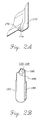
- a hinge assembly for hinge-coupling a flip-cover 106 and a body 112 of a portable wireless phone together forms a pipe-type hinge arm 124 at an end portion of the flip-cover 106.
- Two individually manufactured hinge pins 136 and 148 and a coil spring 142 disposed between the two hinge pins 136 and 148 are inserted into the pipe-type hinge arm 124.
- a pin-shaped cam follower 176 formed of metal is fixed to an portion 154 for receiving the hinge pins 136 and 148 in the body 112. The receiving portion is opposingly formed for each hinge pin.
- the coil spring 142 is inserted to elastically function between the hinge pins 136 and 148.
- the cam follower 176 is fixed to a housing such that a cam surface of the hinge pins 136 and 148 can surface-contact the cam follower 176.
- a protrusion 198 and an indent 196 are formed and key members 186 and 192 protrude in a lengthwise direction at the outer circumferential surface of each of the hinge pins 136 and 148.
- Key slots 130 are formed opposingly at the inner circumferential surface of the hinge arm 124 so that the key members 186 and 192 can move together in a horizontal direction.
- each hinge pin 136 and 148 contacts the cam follower 176 being engaged with each other due to an elastic force of the coil spring 142 during rotating.
- the flip-cover 106 is positioned still at either opening or shutting position by the hinge pins 136 and 148 to which the elastic force by the coil spring 142 is applied.
- the indent 196 and the protrusion 198 are formed at both ends of the hinge pins 136 and 148, and the key members 186 and 192 are protrude at the outer circumferential surface of each of the hinge pins 136 and 148 so that the key members 186 and 192 can horizontally move along the key slots 130 formed at the inner circumferential surface of the hinge arm 124. Accordingly, the cam surface of the hinge pins 136 and 148 contacts the cam follower 176 so that the opening and shutting positions of the cover 106 are maintained.
- the cam surfaces of the hinge pins wear out due to the friction between members of the heterogeneous material, i.e., the cam surface of the plastic hinge pins 136 and 148 and that of the metal cam follower 176.
- the flip-cover 106 is detached from the body 112 due to the coil spring 142 so that the hinge assembly elements are often lost. Further, in such a case, cracks occur on the body 112 where the cam follower 176 is formed or both ends of the hinge arm 124. It is cumbersome to change the flip-cover or the entire body of the cellular phone.
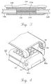
- the flip modules M1 and M2 installed in a receiving space of a case body 80 are each comprised of a hinge housing 30, a hinge shaft 40 having a shaft 41 at one end thereof and a protrusion 42 at the other end thereof and being inserted into the hinge housing 30, a cam hinge 50 having an indent 51a and a protrusion 51b at the same one end thereof so that the protrusion 42 is engaged with the indent 51a, a hinge cover 70 having a hooking protrusion 72 to be coupled with the hinge housing 30, and a coil spring 60 installed between the cam hinge 50 and the hinge cover 70.
- the one side of the hinge housing 30 is a semi-circular surface and the other side thereof is a plane so that both portions are assembled to have a different shape from each other considering the sharing of parts for the left and right sides in view of an assembler and the convenience for assembly.
- a guide slit 31 is formed in a lengthwise direction on the upper portion of the hinge housing 30 and hooking grooves 33 are formed on both sides thereof. Also, a hinge opening 32 is formed on the other end thereof.
- the hinge shaft 40 inserted into the hinge housing 30 has the shaft 41 and the protrusion 42 respectively at one and the other ends thereof.
- Plane surface 43 are formed by slicing off each side portion of an end 44 of the shaft 41 so as to form a D-shaped cross-section.
- the angle made by the plane 43 of the hinge shaft 40 and the protrusion 42 is set considering a communication angle.
- a disassembly groove 45 is formed at the central surface of the end 44 of the shaft 41 to facilitate the fixing of a thin pin in disassembling the flip module.
- the length in a lengthwise direction of the plane having both sides cut in a D-shaped cross-section is determined according to the hooking amount when the end portion of the hinge shaft is inserted into the hooking groove of the flip-cover. That is, by adjusting the above hooking amount within 1-2.5mm, the flip-cover does not easily detached from the case body when assembled and cracks do not occur at around the rotation portion of the flip-cover when the flip-cover is forcedly opened.
- the indent 51a is formed at the center portion of one end of the cam hinge 50 so that the sliding surface-contact of the protrusion 42 is possible. Accordingly, the protrusion 51a is formed on each side thereof.
- a cam hinge protrusion 52 protrudes so that the cam hinge can be horizontally moved along the guide slit 31 of the hinge housing 30, and a spring fixing protrusion 53 is formed on the other side thereof.
- a hinge cover protrusion 71 protrudes so as to be inserted into the guide slit 31 and a fixing protrusion 73 to be installed fast to the receiving space of the case body is formed on the other side thereof.
- the coil spring 60 installed between the cam hinge 50 and the hinge cover 70 operates elastically with respect to the cam hinge 50 when being completely assembled into the hinge housing 30.
- each supporting wall 82 and each fixing wall 83 perpendicular to the supporting wall 82 are formed and an insertion hole 81b to receive the fixing protrusion 73 of the hinge cover 70 is formed in each fixing wall 83.
- a hooking opening 92 is formed in the rotation portion 93 of the flip-cover to be coupled with the case body 80.
- the shaft 41 of the hinge shaft 40 is inserted into the hinge opening 32 of the hinge housing 30, and then, the hinge shaft 40 is inserted into the hinge housing 30 in a direction of engaging the protrusion 51b and the indent 51a of the cam hinge 50 with the protrusion 42 of the hinge shaft 40.
- the hooking protrusion 72 is inserted into the hooking groove 33 of the hinge housing 30 by applying a predetermined force while the coil spring 60 is fixed to the fixing protrusion of the hinge cover 70.
- the fixing protrusion 73 of the flip module M1 is first inserted into the insertion hole 81b of the fixing wall 83. Then, the shaft 41 of the flip module is inserted into the hinge opening 32 while being pushed inwardly by a predetermined force.
- the flip modules M1 and M2 are installed in the case body 80. In doing so, as shown in FIG. 7, the flip module M1 is installed so as to have the guide slit 31 face upward and the other flip module M2 is installed to have the guide slit 31 face the inside of the case body for the opening and shutting angle of the flip-cover 90.
- a discussion of the installation of the flip module M2 to the case body after setting the installation angle has been omitted since the installation thereof is the same as that of the flip module M1.
- each flip-cover M1 and M2 at respective receiving space at a rectangular angle is because, since being elastically supported by the coil spring 60, the cam hinge 50 can horizontally move within limit and thus restoring force, occurring when the horizontal moving distance changes according to the phase of the protrusion 51b of the cam hinge 50 directly receiving the restoration force of the spring 60 during the rotation of the hinge shaft 40, i.e., the rotation of the flip-cover 90, provides moment for the rotation of the button cover.
- an opening angle (about 135°) and shutting angle (0°) must be maintained during opening and shutting of the button cover.
- a disassembly groove 91 is formed at the rotation portion 93 of the flip-cover 90 to prevent cracks of the rotation portion 93 of the flip-cover 90, when the flip-cover 90 installed at the case body 80 receives excessive force by a user to be detached.
- the flip-cover 90 can be detached from the case body 80 by inserting a thin pin into the disassembly groove 91 and intentionally applying force to the flip-cover 90 over a predetermined angle.
- the latter method is utilizing the flexibility of plastic material of the disassembly groove 91, i.e., impact by forcedly applying a force during communication can be absorbed.
- both rotation portions 93 of the flip-cover 90 separate wide in an outward direction. Then, if the force is applied continuously, the flip-cover 90 is detached from the case body 80. That is, the end portion of 41 of the shaft 40 inserted into the hooking groove 92 escapes therefrom.
- the thin pin is inserted into the disassembly groove 45 formed at the hinge shaft 40 and the pin is pushed in the inward direction with a predetermined force.
- the hinge shaft 40 being elastically supported by the coil spring 60 moves inwardly. Then, when the end portion 41 of the hinge shaft is lifted up, the fixing protrusion 73 of the flip module M1 escapes from the insertion hole 81b of the fixing wall 83 so that the flip module M1 is detached from the receiving space of the case body.
- the fixing protrusion 73 of the flip module M2 escapes from the insertion hole 81b of the fixing wall 83 so that the flip module M2 is detached from the receiving space of the case body 80.
- the hooking protrusion 72 of the hinge cover 70 fixed to the hooking groove 33 of the hinge housing 30 is pushed inward and thus the hinge cover 70 is pushed outward by the coil spring 60 installed inside the hinge housing 30.
- the cam hinge 50 contacting the protrusion 42 of the hinge shaft 40 retreats along the slope of the indent 51a to reach the top of the protrusion 51b (the cam hinge of the flip module moves horizontally). Then, the cam hinge 50 slide down along the other slop at the other side. At this stage, the flip-cover 90 stops such action at a point where the protrusion 42 is engaged with the indent 51a of the cam hinge by the restoration force of the coil spring 60 so that an available angle for communication (about 135°) is maintained.
- the flip-cover 90 when the flip-cover 90 is shut, the cam hinge 50 contacting the protrusion 42 of the hinge shaft 40 at the indent 51a slides along the slope of the indent 51a to reach the top of the protrusion 51b. Then, the cam hinge 50 slide down along the other slop at the other side to thereby shut. At this stage, the flip-cover 90 continuously receives further rotatably shutting force by the restoration force of the spring 60 of the flip module.
- the cam hinge moves horizontally during the rotation of the cover.
- the attaching and detaching of the flip-cover and the flip module is easy. Also, by forming the disassembly groove, the disassembly and assembly process is facilitated and cracks on the flip-cover and the loss of parts occurring when the flip-cover is detached can be prevented. Further, by installing the flip modules on both sides of the case body and forming the flip elements of the same material, reduced friction occurs and concurrently the performance thereof improves to thereby provide improved reliability.
Landscapes
- Engineering & Computer Science (AREA)
- Signal Processing (AREA)
- Telephone Set Structure (AREA)
- Pivots And Pivotal Connections (AREA)
- Casings For Electric Apparatus (AREA)
- Transceivers (AREA)
- Mobile Radio Communication Systems (AREA)
Applications Claiming Priority (4)
| Application Number | Priority Date | Filing Date | Title |
|---|---|---|---|
| KR2019950025322U KR0127700Y1 (ko) | 1995-09-19 | 1995-09-19 | 휴대용 전화기의 버튼 커버 개폐장치 |
| KR9525322U | 1995-09-19 | ||
| KR9609131U | 1996-04-24 | ||
| KR2019960009131U KR200141099Y1 (ko) | 1995-09-19 | 1996-04-24 | 휴대용 전화기의 버튼커버 개페장치 |
Publications (3)
| Publication Number | Publication Date |
|---|---|
| EP0765063A2 true EP0765063A2 (de) | 1997-03-26 |
| EP0765063A3 EP0765063A3 (de) | 2000-04-05 |
| EP0765063B1 EP0765063B1 (de) | 2003-09-03 |
Family
ID=26631205
Family Applications (1)
| Application Number | Title | Priority Date | Filing Date |
|---|---|---|---|
| EP96114493A Expired - Lifetime EP0765063B1 (de) | 1995-09-19 | 1996-09-10 | Scharniermechanismus für ein aufklappbares elektronisches Gerät |
Country Status (10)
| Country | Link |
|---|---|
| US (1) | US5697124A (de) |
| EP (1) | EP0765063B1 (de) |
| JP (1) | JP2796275B2 (de) |
| KR (1) | KR200141099Y1 (de) |
| CN (1) | CN1080532C (de) |
| AU (1) | AU695133B2 (de) |
| CA (1) | CA2185835C (de) |
| DE (1) | DE69629776T2 (de) |
| ES (1) | ES2206535T3 (de) |
| RU (1) | RU2121050C1 (de) |
Cited By (13)
| Publication number | Priority date | Publication date | Assignee | Title |
|---|---|---|---|---|
| WO1998049814A1 (en) * | 1997-04-26 | 1998-11-05 | Samsung Electronics Co., Ltd. | Microphone connecting device for flip type portable telephone |
| GB2330381A (en) * | 1997-10-15 | 1999-04-21 | Motorola Inc | Hinge for a Foldable Device |
| WO1999021342A1 (en) * | 1997-10-22 | 1999-04-29 | Matsushita Electric Industrial Co., Ltd. | Housing device with cover |
| EP0923215A2 (de) * | 1997-12-11 | 1999-06-16 | SAMSUNG ELECTRONICS Co. Ltd. | Gelenkmechanismus für ein tragbares Telefon |
| GB2333558A (en) * | 1998-01-26 | 1999-07-28 | Motorola Inc | Hinge for a wireless communication device |
| EP0961459A2 (de) * | 1998-05-29 | 1999-12-01 | Nokia Mobile Phones Ltd. | Gelenkmechanismus für ein tragbares Telefon |
| EP1119154A2 (de) * | 2000-01-18 | 2001-07-25 | Kabushiki Kaisha Strawberry Corporation | Öffnungs- und Schliessstruktur für eine an einem tragbaren Telefon befestigte Klappe |
| US6280258B1 (en) | 1998-02-26 | 2001-08-28 | Telefonaktiebolaget Lm Ericsson (Publ) | Arrangements relating to electrical connections between apparatuses containing electrical circuitry |
| EP1312739A1 (de) * | 2000-08-25 | 2003-05-21 | Sugatsune Kogyo Co., Ltd. | Faltbares mobiltelefon |
| EP1342875A1 (de) * | 2002-03-07 | 2003-09-10 | Fu Luong Hi-Tech Co Ltd | Scharnier mit Rückführvorrichtung zum automatischen Schliessen einer Tür |
| EP1382785A2 (de) * | 2002-07-19 | 2004-01-21 | Samsung Electronics Co., Ltd. | Tragbare Klapptelefon mit einem Charnier zur mechanischen und elektrischen Verbindung zwischen Klappdeckel und Telefon |
| US6807712B2 (en) | 2000-06-29 | 2004-10-26 | Nokia Mobile Phones Ltd. | Hinge having engagement surface to restrain rotational movement and electronic device containing such a hinge |
| FR2860025A1 (fr) * | 2003-09-18 | 2005-03-25 | Mitsubishi Electric Corp | Structure de charniere et appareil de communication |
Families Citing this family (76)
| Publication number | Priority date | Publication date | Assignee | Title |
|---|---|---|---|---|
| FI961587A (fi) * | 1996-04-11 | 1997-10-12 | Nokia Mobile Phones Ltd | Saranamekanismi kokoontaitettavan laitteen kahden osan kiinnittämiseksi kääntyvästi toisiinsa |
| US6256481B1 (en) * | 1997-04-26 | 2001-07-03 | Samsung Electronics Co., Ltd. | Microphone connecting device for flip type portable telephone |
| JP3076265B2 (ja) * | 1997-05-30 | 2000-08-14 | 静岡日本電気株式会社 | 電子機器のヒンジ構造 |
| US6141831A (en) * | 1997-12-09 | 2000-11-07 | Cema Technologies, Inc. | Bistable hinge mechanism |
| GB2332925A (en) * | 1998-01-05 | 1999-07-07 | Siemens Ag | Hinge arrangement. |
| EP0961457B1 (de) * | 1998-05-26 | 2004-11-17 | Samsung Electronics Co., Ltd. | Gelenkmechanismus für ein tragbares Telefon |
| US6122801A (en) * | 1998-05-28 | 2000-09-26 | Telefonaktiebolaget Lm Ericsson | Hinge mechanism |
| US6104916A (en) * | 1998-06-15 | 2000-08-15 | Motorola, Inc. | Hinge pin |
| KR100534537B1 (ko) * | 1998-07-27 | 2006-03-20 | 피닉스코리아 주식회사 | 무선전화기용힌지및그제조방법과힌지제조장치 |
| US5996179A (en) * | 1998-08-07 | 1999-12-07 | Chin-Fu Huong & Li-Hua Liu | Device for preventing inadvertent pressing of push button keys |
| JP4495284B2 (ja) * | 1999-11-17 | 2010-06-30 | 株式会社岡村製作所 | ディスプレイ支持装置 |
| JP2001355371A (ja) * | 2000-06-14 | 2001-12-26 | Kato Electrical Mach Co Ltd | 小型ヒンジ装置 |
| JP2002039161A (ja) * | 2000-07-31 | 2002-02-06 | Nifco Inc | ヒンジユニット及びヒンジ構造 |
| JP3825627B2 (ja) * | 2000-12-14 | 2006-09-27 | スガツネ工業株式会社 | ヒンジ装置及び携帯電話器 |
| TW521117B (en) * | 2001-01-04 | 2003-02-21 | Kato Electric & Machinary Co | A snap fit hinge |
| KR200241123Y1 (ko) * | 2001-04-25 | 2001-10-12 | 원종림 | 이동통신단말기의 커버 개폐장치 |
| JP3643787B2 (ja) * | 2001-05-09 | 2005-04-27 | 三洋電機株式会社 | 折畳み式携帯端末機器 |
| KR100378404B1 (ko) * | 2001-05-31 | 2003-03-29 | 삼성전자주식회사 | 멀티 앵글 힌지캠을 구비한 휴대용 단말기의 힌지 장치 |
| JP2003120655A (ja) * | 2001-10-15 | 2003-04-23 | Ohashi Technica Inc | ヒンジ装置及びそれを用いた携帯電話機 |
| TW576080B (en) * | 2002-03-01 | 2004-02-11 | Benq Corp | Hinge device |
| TW577213B (en) * | 2002-03-14 | 2004-02-21 | Benq Corp | Flipper phone having a hinge mechanism with auto-lock function |
| KR100461016B1 (ko) * | 2002-03-21 | 2004-12-09 | 주식회사 엠투시스 | 회전속도감속장치와 이를 사용한 휴대폰 커버 개폐장치 |
| TW545614U (en) * | 2002-04-18 | 2003-08-01 | Quanta Comp Inc | Flat panel display and its foldable base |
| DE10313563A1 (de) * | 2002-07-02 | 2004-01-22 | Samsung Electro-Mechanics Co., Ltd., Suwon | Automatisch klappbares Mobiltelefon |
| KR100504047B1 (ko) * | 2002-07-22 | 2005-07-27 | 삼성전자주식회사 | 도어 회전 장치 |
| US20040020012A1 (en) * | 2002-08-02 | 2004-02-05 | Gupte Sheel A. | Self-contained hinge for flip-style device |
| KR100629405B1 (ko) * | 2002-10-17 | 2006-09-29 | 피닉스코리아 주식회사 | 힌지장치 |
| KR100492554B1 (ko) * | 2002-11-29 | 2005-06-02 | 엘지전자 주식회사 | 휴대용 단말기의 힌지 장치 |
| KR100969747B1 (ko) * | 2003-01-06 | 2010-07-13 | 삼성전자주식회사 | 힌지 장치를 이용한 그라운드 접속 장치를 구비하는휴대용 무선 단말기 |
| JP2004211864A (ja) * | 2003-01-08 | 2004-07-29 | Matsushita Electric Ind Co Ltd | 開閉装置 |
| JP4026506B2 (ja) * | 2003-02-14 | 2007-12-26 | 松下電器産業株式会社 | 開閉装置及びこれを用いた電子機器 |
| TW572566U (en) * | 2003-05-23 | 2004-01-11 | Hon Hai Prec Ind Co Ltd | Hinge |
| TW572125U (en) * | 2003-05-30 | 2004-01-11 | Hon Hai Prec Ind Co Ltd | Hinge mechanism |
| TW573903U (en) * | 2003-06-06 | 2004-01-21 | Hon Hai Prec Ind Co Ltd | Hinge of handy machine |
| US7065834B2 (en) * | 2003-06-09 | 2006-06-27 | Southco, Inc. | Bistable hinge with dampening mechanism |
| KR100560682B1 (ko) * | 2003-06-19 | 2006-03-16 | 삼성전자주식회사 | 저장고 |
| JP4583307B2 (ja) * | 2003-07-28 | 2010-11-17 | 富士通株式会社 | 移動式無線通信装置 |
| US20050138771A1 (en) * | 2003-12-30 | 2005-06-30 | Ding-Hone Su | Hinge |
| JP4488490B2 (ja) * | 2004-01-09 | 2010-06-23 | スガツネ工業株式会社 | ヒンジ装置 |
| US20050220294A1 (en) * | 2004-02-02 | 2005-10-06 | Amphenol-T&M Antennas | Push-button hinge for handheld devices |
| CN100411405C (zh) * | 2004-04-02 | 2008-08-13 | 华硕电脑股份有限公司 | 具有枢接结构的电子装置 |
| KR20070027576A (ko) | 2004-06-08 | 2007-03-09 | 암페놀 티 앤드 엠 안테나즈 | 휴대 장치용 평행 평판 회전 힌지 |
| US20060193469A1 (en) * | 2004-06-08 | 2006-08-31 | Tony Kfoury | Parallel plane rotation hinge for a portable device |
| US7458840B2 (en) * | 2004-09-15 | 2008-12-02 | 3M Innovative Properties Company | Cap configured to removably connect to an insulation displacement connector block |
| KR100594016B1 (ko) * | 2004-10-04 | 2006-06-30 | 삼성전자주식회사 | 휴대용 단말기의 스윙 힌지 장치 |
| CN2757504Y (zh) * | 2004-12-03 | 2006-02-08 | 深圳富泰宏精密工业有限公司 | 铰链结构 |
| KR100689378B1 (ko) * | 2005-01-20 | 2007-03-02 | 삼성전자주식회사 | 휴대용 단말기의 힌지 장치 |
| CN1940315B (zh) * | 2005-09-30 | 2010-12-29 | 深圳富泰宏精密工业有限公司 | 铰链结构及应用该铰链结构的便携式电子装置 |
| CN1940316A (zh) * | 2005-09-30 | 2007-04-04 | 深圳富泰宏精密工业有限公司 | 铰链结构及应用该铰链结构的便携式电子装置 |
| CN1959135B (zh) * | 2005-11-04 | 2011-06-29 | 深圳富泰宏精密工业有限公司 | 铰链结构及应用该铰链结构的折叠式电子装置 |
| US7383618B2 (en) * | 2005-11-23 | 2008-06-10 | Shin Zu Shing Co., Ltd. | Hinge for a portable device |
| US8104142B2 (en) * | 2006-03-02 | 2012-01-31 | Southco, Inc. | Drop-in damped hinge module |
| KR100701500B1 (ko) * | 2006-06-16 | 2007-03-29 | 주식회사 엠투시스 | 휴대 단말기용 개폐장치 |
| US20090300882A1 (en) * | 2006-06-30 | 2009-12-10 | Yoshitaka Hayashi | Hinge Device and Electronic Apparatus Using The Hinge Device |
| US20080040887A1 (en) * | 2006-08-16 | 2008-02-21 | Dickerson Harry L | Friction hinge for electronic apparatus |
| KR100849318B1 (ko) * | 2006-08-22 | 2008-07-29 | 삼성전자주식회사 | 힌지 장치 및 그를 구비하는 휴대용 단말기 |
| CN101583254B (zh) * | 2008-05-16 | 2012-06-13 | 深圳富泰宏精密工业有限公司 | 保护盖结构 |
| US20090320239A1 (en) * | 2008-06-26 | 2009-12-31 | Nokia Corporation | Apparatus for fold hinge assemblies for electronic devices and associated methods |
| BRMU8801927Y1 (pt) * | 2008-09-01 | 2017-04-18 | Electrolux Do Brasil S/A | estrutura de articulação de haste de prateleira deslizante |
| JP4908484B2 (ja) | 2008-11-27 | 2012-04-04 | 三菱製鋼株式会社 | 回転角度規制機構付きセミオート型ヒンジ |
| CN201351674Y (zh) * | 2008-12-10 | 2009-11-25 | 康准电子科技(昆山)有限公司 | 枢纽器 |
| CN101894934B (zh) * | 2009-05-18 | 2013-06-05 | 鸿富锦精密工业(深圳)有限公司 | 导电机构及采用该导电机构的电子装置 |
| JP5247631B2 (ja) * | 2009-08-27 | 2013-07-24 | キヤノン株式会社 | 電子機器 |
| US8477505B2 (en) * | 2009-09-29 | 2013-07-02 | Netgear, Inc. | Peripheral device with limited relative angular movement |
| CN102196682A (zh) * | 2010-03-03 | 2011-09-21 | 深圳富泰宏精密工业有限公司 | 便携式电子装置 |
| KR101676880B1 (ko) * | 2010-07-01 | 2016-11-16 | 삼성전자주식회사 | 폴더형 휴대용 통신 장치의 힌지 장치 |
| CN102758998A (zh) * | 2011-04-27 | 2012-10-31 | 深圳富泰宏精密工业有限公司 | 支撑架 |
| US9370961B2 (en) * | 2012-08-24 | 2016-06-21 | James John Mach | Assisted opening compact novelty utensil |
| KR101947919B1 (ko) * | 2017-09-26 | 2019-02-13 | 원종석 | 반자동 클로저 및 스토퍼 기능을 갖는 도어힌지 |
| CN108161963A (zh) * | 2018-02-01 | 2018-06-15 | 深圳市智能机器人研究院 | 机器人抓手 |
| JP7353160B2 (ja) * | 2019-12-20 | 2023-09-29 | アイホン株式会社 | インターホン機器 |
| JP7369217B2 (ja) | 2021-01-29 | 2023-10-25 | サムスン エレクトロニクス カンパニー リミテッド | ヒンジ構造及びヒンジ構造を含む電子装置 |
| CN114810800B (zh) * | 2021-01-29 | 2024-08-09 | 三星电子株式会社 | 铰链结构和包括铰链结构的电子装置 |
| US11385687B1 (en) | 2021-01-29 | 2022-07-12 | Samsung Electronics Co., Ltd. | Hinge structure and electronic device including the same |
| CN113417932B (zh) * | 2021-07-21 | 2022-03-15 | 燕山大学 | 可控杆或轴周向转动和轴向移动的转角定位装置 |
| CN117847076A (zh) * | 2023-03-22 | 2024-04-09 | 荣耀终端有限公司 | 转轴机构及终端设备 |
Citations (3)
| Publication number | Priority date | Publication date | Assignee | Title |
|---|---|---|---|---|
| DE4134650C1 (en) * | 1991-10-19 | 1992-10-08 | Loewe Opta Gmbh, 8640 Kronach, De | Handset esp. for cordless telephone - has integrated loudspeaker at one end and microphone in pivotable flap at other end |
| US5274882A (en) * | 1992-03-03 | 1994-01-04 | Ericsson Ge Mobile Communications Inc. | Hinge mechanism |
| US5317785A (en) * | 1991-09-30 | 1994-06-07 | Nec Corporation | Hinge mechanism for foldable electronic apparatus |
Family Cites Families (19)
| Publication number | Priority date | Publication date | Assignee | Title |
|---|---|---|---|---|
| US514890A (en) * | 1894-02-13 | Satchel or bag frame | ||
| US2146391A (en) * | 1936-10-09 | 1939-02-07 | Tuttle & Bailey Inc | Damper for registers |
| US3026559A (en) * | 1958-11-13 | 1962-03-27 | Sanymetal Products Company Inc | Door operating hinge assembly |
| US3353206A (en) * | 1965-06-15 | 1967-11-21 | Kerman Mark | Positioning hinge for doors and the like |
| US3518716A (en) * | 1968-05-24 | 1970-07-07 | Keystone Consolidated Ind Inc | Self-closing hinge |
| SU450019A1 (ru) * | 1973-01-26 | 1974-11-15 | Предприятие П/Я В-2203 | Петлевой шарнир дл откидывающихс крышек |
| SU556219A1 (ru) * | 1974-07-05 | 1977-04-30 | Предприятие П/Я Г-4448 | Устройство дл фиксации в открытом положении крышки |
| US4897873A (en) * | 1988-11-04 | 1990-01-30 | Motorola, Inc. | Multipurpose hinge apparatus for foldable telephones |
| KR920002749Y1 (ko) * | 1989-09-23 | 1992-04-30 | 현대전자산업 주식회사 | 워드 프로세서의 액정 표시판 경사각도 조절장치 |
| US5031270A (en) * | 1990-03-15 | 1991-07-16 | Simpson Lee | Friction hinge |
| JPH0491541A (ja) * | 1990-08-07 | 1992-03-25 | Fujitsu Ltd | 電話機用ハンドセット |
| JP2856263B2 (ja) * | 1990-09-07 | 1999-02-10 | 富士通株式会社 | 携帯電話機 |
| US5125131A (en) * | 1991-01-14 | 1992-06-30 | Hughes Aircraft Company | Hinge locking mechanism with disengage action |
| JPH05506768A (ja) * | 1991-03-28 | 1993-09-30 | モトローラ・インコーポレイテッド | 折り畳み可能な無線電話装置用ヒンジ装置 |
| US5185790A (en) * | 1991-03-28 | 1993-02-09 | Motorola, Inc. | Multiposition detenting hinge apparatus |
| DE4291238C2 (de) * | 1991-05-06 | 1995-05-04 | Motorola Inc | Zusammenklappbares Funktelefon |
| US5317765A (en) * | 1992-09-08 | 1994-06-07 | Gerry Baby Products Company | Collapsible infant bath ring |
| JPH077274A (ja) * | 1993-06-18 | 1995-01-10 | Fujitsu Ltd | 携帯形小型装置 |
| ATE176208T1 (de) * | 1993-06-21 | 1999-02-15 | Motorola Inc | Reibungskupplung für ein doppelscharniergelenk |
-
1996
- 1996-04-24 KR KR2019960009131U patent/KR200141099Y1/ko not_active IP Right Cessation
- 1996-09-06 US US08/708,985 patent/US5697124A/en not_active Expired - Lifetime
- 1996-09-10 ES ES96114493T patent/ES2206535T3/es not_active Expired - Lifetime
- 1996-09-10 EP EP96114493A patent/EP0765063B1/de not_active Expired - Lifetime
- 1996-09-10 DE DE69629776T patent/DE69629776T2/de not_active Expired - Fee Related
- 1996-09-18 AU AU65694/96A patent/AU695133B2/en not_active Ceased
- 1996-09-18 RU RU96118493A patent/RU2121050C1/ru not_active IP Right Cessation
- 1996-09-18 CA CA002185835A patent/CA2185835C/en not_active Expired - Fee Related
- 1996-09-19 CN CN96122053A patent/CN1080532C/zh not_active Expired - Fee Related
- 1996-09-19 JP JP8248306A patent/JP2796275B2/ja not_active Expired - Fee Related
Patent Citations (3)
| Publication number | Priority date | Publication date | Assignee | Title |
|---|---|---|---|---|
| US5317785A (en) * | 1991-09-30 | 1994-06-07 | Nec Corporation | Hinge mechanism for foldable electronic apparatus |
| DE4134650C1 (en) * | 1991-10-19 | 1992-10-08 | Loewe Opta Gmbh, 8640 Kronach, De | Handset esp. for cordless telephone - has integrated loudspeaker at one end and microphone in pivotable flap at other end |
| US5274882A (en) * | 1992-03-03 | 1994-01-04 | Ericsson Ge Mobile Communications Inc. | Hinge mechanism |
Cited By (24)
| Publication number | Priority date | Publication date | Assignee | Title |
|---|---|---|---|---|
| WO1998049814A1 (en) * | 1997-04-26 | 1998-11-05 | Samsung Electronics Co., Ltd. | Microphone connecting device for flip type portable telephone |
| GB2330381B (en) * | 1997-10-15 | 2002-02-20 | Motorola Inc | Hinge suitable for use in a foldable device |
| GB2330381A (en) * | 1997-10-15 | 1999-04-21 | Motorola Inc | Hinge for a Foldable Device |
| WO1999021342A1 (en) * | 1997-10-22 | 1999-04-29 | Matsushita Electric Industrial Co., Ltd. | Housing device with cover |
| US6123401A (en) * | 1997-10-22 | 2000-09-26 | Matsushita Electric Industrial Co., Ltd. | Housing device with cover |
| EP0923215A2 (de) * | 1997-12-11 | 1999-06-16 | SAMSUNG ELECTRONICS Co. Ltd. | Gelenkmechanismus für ein tragbares Telefon |
| EP0923215A3 (de) * | 1997-12-11 | 2004-03-03 | SAMSUNG ELECTRONICS Co. Ltd. | Gelenkmechanismus für ein tragbares Telefon |
| GB2333558A (en) * | 1998-01-26 | 1999-07-28 | Motorola Inc | Hinge for a wireless communication device |
| FR2774237A1 (fr) * | 1998-01-26 | 1999-07-30 | Motorola Inc | Mecanisme a charniere pour dispositif de communication sans fil |
| US6280258B1 (en) | 1998-02-26 | 2001-08-28 | Telefonaktiebolaget Lm Ericsson (Publ) | Arrangements relating to electrical connections between apparatuses containing electrical circuitry |
| EP0961459A3 (de) * | 1998-05-29 | 2003-07-30 | Nokia Corporation | Gelenkmechanismus für ein tragbares Telefon |
| EP0961459A2 (de) * | 1998-05-29 | 1999-12-01 | Nokia Mobile Phones Ltd. | Gelenkmechanismus für ein tragbares Telefon |
| EP1119154A2 (de) * | 2000-01-18 | 2001-07-25 | Kabushiki Kaisha Strawberry Corporation | Öffnungs- und Schliessstruktur für eine an einem tragbaren Telefon befestigte Klappe |
| US6985759B2 (en) | 2000-01-18 | 2006-01-10 | Kabushiki Kaisha Strawberry Corporation | Opening/closing structure for a flip attached to a portable phone |
| EP1119154A3 (de) * | 2000-01-18 | 2003-10-01 | Kabushiki Kaisha Strawberry Corporation | Öffnungs- und Schliessstruktur für eine an einem tragbaren Telefon befestigte Klappe |
| US6807712B2 (en) | 2000-06-29 | 2004-10-26 | Nokia Mobile Phones Ltd. | Hinge having engagement surface to restrain rotational movement and electronic device containing such a hinge |
| EP1312739A4 (de) * | 2000-08-25 | 2004-10-27 | Sugatsune Kogyo | Faltbares mobiltelefon |
| EP1312739A1 (de) * | 2000-08-25 | 2003-05-21 | Sugatsune Kogyo Co., Ltd. | Faltbares mobiltelefon |
| US7076280B2 (en) | 2000-08-25 | 2006-07-11 | Sugatsune Kogyo Co., Ltd. | Foldable type cellular telephone |
| EP1342875A1 (de) * | 2002-03-07 | 2003-09-10 | Fu Luong Hi-Tech Co Ltd | Scharnier mit Rückführvorrichtung zum automatischen Schliessen einer Tür |
| EP1382785A3 (de) * | 2002-07-19 | 2004-05-19 | Samsung Electronics Co., Ltd. | Tragbare Klapptelefon mit einem Charnier zur mechanischen und elektrischen Verbindung zwischen Klappdeckel und Telefon |
| EP1382785A2 (de) * | 2002-07-19 | 2004-01-21 | Samsung Electronics Co., Ltd. | Tragbare Klapptelefon mit einem Charnier zur mechanischen und elektrischen Verbindung zwischen Klappdeckel und Telefon |
| US6808402B2 (en) | 2002-07-19 | 2004-10-26 | Samsung Electronics Co., Ltd. | Portable wireless terminal with a ground connecting device using a hinge module and method for using the same |
| FR2860025A1 (fr) * | 2003-09-18 | 2005-03-25 | Mitsubishi Electric Corp | Structure de charniere et appareil de communication |
Also Published As
| Publication number | Publication date |
|---|---|
| RU2121050C1 (ru) | 1998-10-27 |
| DE69629776D1 (de) | 2003-10-09 |
| EP0765063B1 (de) | 2003-09-03 |
| KR200141099Y1 (ko) | 1999-05-15 |
| DE69629776T2 (de) | 2004-03-25 |
| ES2206535T3 (es) | 2004-05-16 |
| CA2185835C (en) | 2002-06-04 |
| KR970015497U (ko) | 1997-04-28 |
| CN1080532C (zh) | 2002-03-06 |
| JP2796275B2 (ja) | 1998-09-10 |
| US5697124A (en) | 1997-12-16 |
| EP0765063A3 (de) | 2000-04-05 |
| AU6569496A (en) | 1997-03-27 |
| CA2185835A1 (en) | 1997-03-20 |
| JPH09130462A (ja) | 1997-05-16 |
| AU695133B2 (en) | 1998-08-06 |
| CN1159136A (zh) | 1997-09-10 |
Similar Documents
| Publication | Publication Date | Title |
|---|---|---|
| EP0765063B1 (de) | Scharniermechanismus für ein aufklappbares elektronisches Gerät | |
| US5905796A (en) | Hinge mechanism for foldable electronic apparatus | |
| US7634838B2 (en) | Hinge and a mobile phone with the hinge | |
| AU655027B2 (en) | Hinge apparatus for foldable radiotelephones | |
| US20050272486A1 (en) | Hinge apparatus and watch type portable terminal having the same | |
| EP1883207B1 (de) | Schwingscharniervorrichtung für ein tragbares Endgerät | |
| EP1220516A2 (de) | Scharniermodul für ein tragbares Funk-Endgerät | |
| US20030163901A1 (en) | Hinge mechanism | |
| KR100991463B1 (ko) | 휴대 단말기용 스윙식 덮개 개폐장치 | |
| US20060154701A1 (en) | Hinge assembly for foldable electronic device | |
| KR100428423B1 (ko) | 이동통신단말기의 커버 개폐장치 | |
| KR100350478B1 (ko) | 휴대용 무선단말기의 힌지장치 | |
| KR20030032223A (ko) | 덮개의 완전개방을 위한 폴더형 휴대폰 | |
| KR100703152B1 (ko) | 휴대 단말기용 슬라이드 힌지모듈 및 이를 이용한 휴대단말기 | |
| KR200289683Y1 (ko) | 이동통신 단말기 | |
| KR0145013B1 (ko) | 셀룰라폰 플립의 개폐장치 | |
| KR100447593B1 (ko) | 이동통신 단말기 | |
| KR200258171Y1 (ko) | 휴대폰의 덮개 개폐장치 | |
| KR101006046B1 (ko) | 휴대용 통신단말기를 개폐하기 위한 슬라이드 조립체 | |
| KR200317857Y1 (ko) | 폴더형 이동통신 단말기의 힌지장치 | |
| KR100483720B1 (ko) | 휴대폰 개폐장치 | |
| KR100678038B1 (ko) | 휴대용 무선 단말기의 힌지 장치 | |
| KR200457463Y1 (ko) | 휴대폰용 슬라이드 힌지 모듈 | |
| KR200303577Y1 (ko) | 이동통신단말기의 커버 힌지장치 | |
| KR200284282Y1 (ko) | 휴대폰 개폐장치 |
Legal Events
| Date | Code | Title | Description |
|---|---|---|---|
| PUAI | Public reference made under article 153(3) epc to a published international application that has entered the european phase |
Free format text: ORIGINAL CODE: 0009012 |
|
| 17P | Request for examination filed |
Effective date: 19960910 |
|
| AK | Designated contracting states |
Kind code of ref document: A2 Designated state(s): DE ES FI FR GB IT SE |
|
| PUAL | Search report despatched |
Free format text: ORIGINAL CODE: 0009013 |
|
| AK | Designated contracting states |
Kind code of ref document: A3 Designated state(s): DE ES FI FR GB IT SE |
|
| 17Q | First examination report despatched |
Effective date: 20020801 |
|
| GRAH | Despatch of communication of intention to grant a patent |
Free format text: ORIGINAL CODE: EPIDOS IGRA |
|
| GRAH | Despatch of communication of intention to grant a patent |
Free format text: ORIGINAL CODE: EPIDOS IGRA |
|
| GRAH | Despatch of communication of intention to grant a patent |
Free format text: ORIGINAL CODE: EPIDOS IGRA |
|
| GRAH | Despatch of communication of intention to grant a patent |
Free format text: ORIGINAL CODE: EPIDOS IGRA |
|
| GRAH | Despatch of communication of intention to grant a patent |
Free format text: ORIGINAL CODE: EPIDOS IGRA |
|
| GRAA | (expected) grant |
Free format text: ORIGINAL CODE: 0009210 |
|
| AK | Designated contracting states |
Kind code of ref document: B1 Designated state(s): DE ES FI FR GB IT SE |
|
| REG | Reference to a national code |
Ref country code: GB Ref legal event code: FG4D |
|
| REF | Corresponds to: |
Ref document number: 69629776 Country of ref document: DE Date of ref document: 20031009 Kind code of ref document: P |
|
| REG | Reference to a national code |
Ref country code: SE Ref legal event code: TRGR |
|
| ET | Fr: translation filed | ||
| REG | Reference to a national code |
Ref country code: ES Ref legal event code: FG2A Ref document number: 2206535 Country of ref document: ES Kind code of ref document: T3 |
|
| PLBE | No opposition filed within time limit |
Free format text: ORIGINAL CODE: 0009261 |
|
| STAA | Information on the status of an ep patent application or granted ep patent |
Free format text: STATUS: NO OPPOSITION FILED WITHIN TIME LIMIT |
|
| 26N | No opposition filed |
Effective date: 20040604 |
|
| PGFP | Annual fee paid to national office [announced via postgrant information from national office to epo] |
Ref country code: DE Payment date: 20070906 Year of fee payment: 12 |
|
| PGFP | Annual fee paid to national office [announced via postgrant information from national office to epo] |
Ref country code: FI Payment date: 20070912 Year of fee payment: 12 |
|
| PGFP | Annual fee paid to national office [announced via postgrant information from national office to epo] |
Ref country code: GB Payment date: 20070905 Year of fee payment: 12 |
|
| PGFP | Annual fee paid to national office [announced via postgrant information from national office to epo] |
Ref country code: SE Payment date: 20070905 Year of fee payment: 12 Ref country code: IT Payment date: 20070926 Year of fee payment: 12 Ref country code: ES Payment date: 20071024 Year of fee payment: 12 |
|
| PGFP | Annual fee paid to national office [announced via postgrant information from national office to epo] |
Ref country code: FR Payment date: 20070914 Year of fee payment: 12 |
|
| GBPC | Gb: european patent ceased through non-payment of renewal fee |
Effective date: 20080910 |
|
| PG25 | Lapsed in a contracting state [announced via postgrant information from national office to epo] |
Ref country code: FI Free format text: LAPSE BECAUSE OF NON-PAYMENT OF DUE FEES Effective date: 20080910 |
|
| REG | Reference to a national code |
Ref country code: FR Ref legal event code: ST Effective date: 20090529 |
|
| PG25 | Lapsed in a contracting state [announced via postgrant information from national office to epo] |
Ref country code: IT Free format text: LAPSE BECAUSE OF NON-PAYMENT OF DUE FEES Effective date: 20080910 Ref country code: DE Free format text: LAPSE BECAUSE OF NON-PAYMENT OF DUE FEES Effective date: 20090401 |
|
| PG25 | Lapsed in a contracting state [announced via postgrant information from national office to epo] |
Ref country code: FR Free format text: LAPSE BECAUSE OF NON-PAYMENT OF DUE FEES Effective date: 20080930 |
|
| REG | Reference to a national code |
Ref country code: ES Ref legal event code: FD2A Effective date: 20080911 |
|
| PG25 | Lapsed in a contracting state [announced via postgrant information from national office to epo] |
Ref country code: GB Free format text: LAPSE BECAUSE OF NON-PAYMENT OF DUE FEES Effective date: 20080910 |
|
| PG25 | Lapsed in a contracting state [announced via postgrant information from national office to epo] |
Ref country code: ES Free format text: LAPSE BECAUSE OF NON-PAYMENT OF DUE FEES Effective date: 20080911 |
|
| PG25 | Lapsed in a contracting state [announced via postgrant information from national office to epo] |
Ref country code: SE Free format text: LAPSE BECAUSE OF NON-PAYMENT OF DUE FEES Effective date: 20080911 |