EP0765003B1 - Elektrischer Kontakt - Google Patents
Elektrischer Kontakt Download PDFInfo
- Publication number
- EP0765003B1 EP0765003B1 EP96114540A EP96114540A EP0765003B1 EP 0765003 B1 EP0765003 B1 EP 0765003B1 EP 96114540 A EP96114540 A EP 96114540A EP 96114540 A EP96114540 A EP 96114540A EP 0765003 B1 EP0765003 B1 EP 0765003B1
- Authority
- EP
- European Patent Office
- Prior art keywords
- shaped
- edge
- electric contact
- dome
- embossment
- Prior art date
- Legal status (The legal status is an assumption and is not a legal conclusion. Google has not performed a legal analysis and makes no representation as to the accuracy of the status listed.)
- Expired - Lifetime
Links
- 239000002184 metal Substances 0.000 claims description 4
- 238000003466 welding Methods 0.000 description 4
- 238000005452 bending Methods 0.000 description 2
- 230000009286 beneficial effect Effects 0.000 description 1
- 238000011161 development Methods 0.000 description 1
- 230000018109 developmental process Effects 0.000 description 1
- 238000004049 embossing Methods 0.000 description 1
- 238000000034 method Methods 0.000 description 1
Images

Classifications
-
- H—ELECTRICITY
- H01—ELECTRIC ELEMENTS
- H01R—ELECTRICALLY-CONDUCTIVE CONNECTIONS; STRUCTURAL ASSOCIATIONS OF A PLURALITY OF MUTUALLY-INSULATED ELECTRICAL CONNECTING ELEMENTS; COUPLING DEVICES; CURRENT COLLECTORS
- H01R13/00—Details of coupling devices of the kinds covered by groups H01R12/70 or H01R24/00 - H01R33/00
- H01R13/02—Contact members
- H01R13/15—Pins, blades or sockets having separate spring member for producing or increasing contact pressure
- H01R13/18—Pins, blades or sockets having separate spring member for producing or increasing contact pressure with the spring member surrounding the socket
Definitions
- the invention relates to an electrical contact with a box-shaped part that is formed from a sheet, has at least four side walls and such is put together that there is a seam in a side wall located on the opposite edge of the sheet butt together with the opposite edges are designed to be at least partially opposing and at least one edge has a protrusion and the other one has corresponding recess.
- An electrical contact is known from EP-A-0 517 139, which is used to establish a connector and a Has pair of contact spring arms.
- the Plug an outer spring body onto a pair of has outer spring arms.
- the outer spring body is formed from a sheet, box-shaped, points at least four side walls and is such put together that there is a seam in a side wall located on the opposite edge of the sheet bump into each other. At this interface is the outer one Spring body closed by welding. Preferably a laser spot welding process is used.
- the exterior The spring body serves to protect the inner contact spring arms.
- the electrical contact known from EP-A-0 517 139 has the Features of the preamble of claim 1 on.
- the seam is to be held here by welding become.
- Both edges have a bent tab on the keep the outer spring arms at a distance.
- An edge points also a locking tab that is bent inwards.
- the edges can overlap in both directions cannot be prevented by this.
- Many electrical contacts have parts that are box-shaped. It becomes such a part specified, which is formed from a sheet, box-shaped is constructed, has at least four side walls and is assembled in such a way that it is in a side wall there is a seam on the opposite edges of the Butting plates together.
- the part is characterized by it from that the opposite edges at least are designed in areas that are opposite to each other and at least one edge a protrusion and the other edge one has corresponding recess.
- the edges can for example, meandering or wavy be designed.
- the part is characterized by it from that the opposite edges each at least an embossed survey or at least one embossed one Have deepening.
- the opposite edges can also have both a deepening and an elevation.
- This configuration of the box-shaped part achieved that the opposite edges are not can overlap. An overlap would become one large distance between the opposite edges.
- embossing as Wells are designed, so in the direction of extend the inside of the box. Then these wells at the same time, for example, as guides for in the box-shaped part introduced other parts serve. Around a particularly good fixation of the edges to each other can achieve this additional with each other be welded. It is particularly beneficial that To weld edges point by point with a laser.
- the part according to the invention is usually made of one stamped sheet metal.
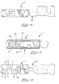
- a stamped part shown in Figures 1-3 This is the sheet box-shaped part 1 made by bending.
- the fourth side wall 2 is from the two part walls 2 'and 2 '' with the respective edges 7 and 8. It is to recognize that the edges 7 and 8 in some areas are designed in the same way.
- the edge 7 points Recesses 11 and 12, while the edge 8 protrusions 9 and has 10.
- the projections 9 and 10 engage in the recesses 11 and 12 a.
- a seam 6 is formed between the both edges, as can be seen in Figure 1.
- Another half-dome shaped Recess 15 is stamped into the edge 7. It ends with their cutting surface 16 exactly on the edge. Through the provided recesses is a pushing the two part walls of wall 2 with lateral force prevented. For additional fixation of the two edges 7, 8 on the seam 6, welding spots 17, 18 can be provided become.
- the part described above can be part of an electrical Be contact, the other means of attaching a Cable or for receiving a contact pin.
- the Figures 4 to 6 is an electrical contact for one Plug connection with an inner contact body 20 and to recognize an outer spring body 1, the Spring body is formed from a sheet, box-shaped is constructed and at least four side walls 2 to 5 having.
- the inner contact body turns into an outer one Spring body 1, the one described in Figures 1 to 3 Part corresponds, introduced.
- To facilitate the management of the inner contact body 20 to be introduced are not only on the seam side of the outer spring body 1 but also 5 dome-shaped on the opposite side Wells 19, 21 provided.
- Part of an electrical contact of the box-shaped is constructed and has the features according to the invention, can not only together with an inner contact body, as described in Figures 3 to 7, are used. It can also be part of another electrical contact be made up of two independent parts is constructed.
Landscapes
- Manufacturing Of Electrical Connectors (AREA)
- Connector Housings Or Holding Contact Members (AREA)
- Connections Effected By Soldering, Adhesion, Or Permanent Deformation (AREA)
Description
Claims (8)
- Elektrischer Kontakt mit einem kastenförmigen Teil, das aus einem Blech geformt ist, zumindest vier Seitenwände aufweist und derart zusammengefügt ist, dass sich in einer Seitenwand eine Naht befindet, an der gegenüberliegende Ränder des Bleches aneinanderstossen, wobei die gegenüberliegenden Ränder (7,8) zumindest bereichsweise gegengleich ausgestaltet sind und zumindest ein Rand (8) einen Überstand (9,10) und der andere Rand (7) eine entsprechende Ausnehmung (11,12) aufweist, dadurch gekennzeichnet, dass die gegenüberliegenden Ränder (7,8) jeweils zumindest eine geprägte Erhebung oder jeweils zumindest eine geprägte Vertiefung (13,14,15) aufweisen, die entlang der Naht an aufeinanderfolgenden Stellen eingeprägt sind.
- Elektrischer Kontakt nach Anspruch 1, dadurch gekennzeichnet, dass sich eine geprägte Erhebung oder Vertiefung (13,14) im Bereich des Überstandes (9,10) befindet.
- Elektrischer Kontakt nach einem der Ansprüche 1 oder 2, dadurch gekennzeichnet, dass die geprägten Vertiefungen (13,14,15) oder Erhebungen kalotten- oder halbkalottenförmig ausgestaltet sind.
- Elektrischer Kontakt nach einem der Ansprüche 1 oder 3, dadurch gekennzeichnet, dass ein Rand (7) eine halbkalottenförmige Erhebung oder Vertiefung (15) aufweist, wobei die Schnittfläche (16) der halbkalottenförmigen Erhebung oder Vertiefung (15) mit dem Rand (7) zusammenfällt.
- Elektrischer Kontakt nach einem der Ansprüche 1 oder 4, dadurch gekennzeichnet, dass ein Rand (8) zwei Überstände (9,10) aufweist, die halbkreisförmig ausgestaltet sind und eine Hälfte einer kalottenförmigen Vertiefung (13,14) oder Erhebung aufnehmen, dass der andere Rand (7) zwei entsprechende halbkreisförmige Ausnehmungen (11,12) aufweist, und zwischen diesen eine halbkalottenförmige Vertiefung (15) oder Erhebung, wobei die Schnittfläche (15) mit dem Rand (7) zusammenfällt.
- Elektrischer Kontakt nach einem der Ansprüche 1 oder 5, dadurch gekennzeichnet, dass die Ränder (7,8) zumindest punktweise miteinander verschweisst sind.
- Elektrischer Kontakt nach einem der Ansprüche 1 bis 6, dadurch gekennzeichnet, dass der Kontakt einen inneren Kontaktkörper (20) aufweist und das kastenförmige Teil einen äusseren Federkörper (1) bildet, der den Kontaktkörper (20) zumindest bereichsweise umgibt.
- Elektrischer Kontakt nach Anspruch 7, dadurch gekennzeichnet, dass der äussere Federkörper (1) auf der Seite (2) mit der Naht (6) und der gegenüberliegenden Seite (5) Vertiefungen (13,14,15,19,21) aufweist, zur Führung des inneren Kontaktkörpers (20).
Applications Claiming Priority (2)
| Application Number | Priority Date | Filing Date | Title |
|---|---|---|---|
| DE19535148 | 1995-09-21 | ||
| DE19535148A DE19535148A1 (de) | 1995-09-21 | 1995-09-21 | Teil eines elektrischen Kontaktes und elektrischer Kontakt |
Publications (2)
| Publication Number | Publication Date |
|---|---|
| EP0765003A1 EP0765003A1 (de) | 1997-03-26 |
| EP0765003B1 true EP0765003B1 (de) | 2000-05-24 |
Family
ID=7772807
Family Applications (1)
| Application Number | Title | Priority Date | Filing Date |
|---|---|---|---|
| EP96114540A Expired - Lifetime EP0765003B1 (de) | 1995-09-21 | 1996-09-11 | Elektrischer Kontakt |
Country Status (3)
| Country | Link |
|---|---|
| US (1) | US5716244A (de) |
| EP (1) | EP0765003B1 (de) |
| DE (2) | DE19535148A1 (de) |
Families Citing this family (15)
| Publication number | Priority date | Publication date | Assignee | Title |
|---|---|---|---|---|
| DE19535148A1 (de) * | 1995-09-21 | 1997-03-27 | Whitaker Corp | Teil eines elektrischen Kontaktes und elektrischer Kontakt |
| JP3724610B2 (ja) * | 1996-10-21 | 2005-12-07 | 住友電装株式会社 | 端子金具のカバー |
| DE19713111A1 (de) * | 1997-03-27 | 1998-10-01 | Whitaker Corp | Elektrische Anschlußklemme und entsprechender elektrischer Kontaktstift |
| US5951308A (en) * | 1997-10-29 | 1999-09-14 | General Motors Corporation | Ignition terminal with welded barrel beam |
| US6099360A (en) * | 1998-12-02 | 2000-08-08 | The Whitaker Corporation | Contact having a force distribution member |
| US8551162B2 (en) * | 2002-12-20 | 2013-10-08 | Medtronic, Inc. | Biologically implantable prosthesis |
| JP2006179362A (ja) * | 2004-12-24 | 2006-07-06 | Jst Mfg Co Ltd | 接続端子およびそれを備えたコネクタ |
| US7422494B2 (en) | 2006-09-29 | 2008-09-09 | Tyco Electronics Corporation | Two-piece electrical terminal |
| US7976353B2 (en) * | 2006-09-29 | 2011-07-12 | Tyco Electronics Corporation | Two-piece electrical terminal |
| EP2642598B1 (de) * | 2012-03-19 | 2017-09-13 | Yazaki Europe Ltd | Elektrisches Endgerät |
| US20150275952A1 (en) * | 2014-03-25 | 2015-10-01 | Fritz Stepper Gmbh & Co. Kg | Plug-on part for a plug connector |
| CN108616017B (zh) * | 2018-03-26 | 2020-07-24 | 番禺得意精密电子工业有限公司 | 转接连接器 |
| JP7281087B2 (ja) * | 2019-11-01 | 2023-05-25 | 株式会社オートネットワーク技術研究所 | 端子接続構造 |
| TWI734244B (zh) * | 2019-11-04 | 2021-07-21 | 大陸商東莞訊滔電子有限公司 | 電性端子以及電連接器 |
| FR3138012B1 (fr) | 2022-07-13 | 2026-03-13 | Somfy Activites Sa | Ensemble cosse-capuchon et système de motorisation associé |
Family Cites Families (13)
| Publication number | Priority date | Publication date | Assignee | Title |
|---|---|---|---|---|
| US4047791A (en) * | 1974-12-06 | 1977-09-13 | Amp Incorporated | Low insertion force receptacle and cammed housing |
| DE8508964U1 (de) * | 1985-03-26 | 1986-12-18 | Grote & Hartmann Gmbh & Co Kg, 5600 Wuppertal | Kastenfeder |
| US4919628A (en) * | 1987-10-19 | 1990-04-24 | Interlock Corporation | Tab receptacle with fixed beam contacts |
| DE8813575U1 (de) * | 1988-10-28 | 1989-01-19 | Grote & Hartmann Gmbh & Co Kg, 5600 Wuppertal | Elektrischer Verbinder |
| US4932906A (en) * | 1988-12-16 | 1990-06-12 | Amp Incorporated | Electrical contact terminal |
| DE4015230A1 (de) * | 1989-05-17 | 1990-11-22 | Amp Inc | Elektrische verbinderanordnung |
| DE9017229U1 (de) * | 1990-12-20 | 1992-04-23 | Grote & Hartmann Gmbh & Co Kg, 5600 Wuppertal | Doppelflachfederkontakt mit Anschlageinrichtung |
| DE9106773U1 (de) * | 1991-06-03 | 1991-07-18 | Amp Inc., Harrisburg, Pa. | Elektrischer Steckkontakt |
| DE9201047U1 (de) * | 1992-01-29 | 1993-06-03 | Grote & Hartmann Gmbh & Co Kg, 5600 Wuppertal | Doppelflachfederkontakt mit Außenüberfeder |
| GB9209948D0 (en) * | 1992-05-08 | 1992-06-24 | Amp Gmbh | Electrical socket terminal |
| FR2698730B1 (fr) * | 1992-11-30 | 1994-12-30 | Cinch Connecteurs Sa | Elément de boîtier de connecteur électrique et organe de contact électrique femelle destiné à être monté dans ledit élément de boîtier. |
| JP2739623B2 (ja) * | 1993-05-17 | 1998-04-15 | 矢崎総業株式会社 | ソケット型ターミナル |
| DE19535148A1 (de) * | 1995-09-21 | 1997-03-27 | Whitaker Corp | Teil eines elektrischen Kontaktes und elektrischer Kontakt |
-
1995
- 1995-09-21 DE DE19535148A patent/DE19535148A1/de not_active Withdrawn
-
1996
- 1996-09-05 US US08/709,459 patent/US5716244A/en not_active Expired - Fee Related
- 1996-09-11 DE DE59605286T patent/DE59605286D1/de not_active Expired - Fee Related
- 1996-09-11 EP EP96114540A patent/EP0765003B1/de not_active Expired - Lifetime
Also Published As
| Publication number | Publication date |
|---|---|
| US5716244A (en) | 1998-02-10 |
| DE19535148A1 (de) | 1997-03-27 |
| DE59605286D1 (de) | 2000-06-29 |
| EP0765003A1 (de) | 1997-03-26 |
Similar Documents
| Publication | Publication Date | Title |
|---|---|---|
| DE69228392T2 (de) | Elektrischer Kontakt | |
| DE69508245T2 (de) | Elektrischer verbinder mit gleitkontakten | |
| DE69223453T2 (de) | Elektrischer Kontakt | |
| EP0196367B1 (de) | Kastenfeder | |
| DE102015110244B4 (de) | Batteriezellengehäuse und Verfahren zu dessen Herstellung | |
| DE69221539T2 (de) | Elektrischer Kontakt | |
| DE19535148A1 (de) | Teil eines elektrischen Kontaktes und elektrischer Kontakt | |
| EP0492086B1 (de) | Doppelflachfederkontakt mit Anschlageinrichtung | |
| DE10335196B3 (de) | Kontaktbuchse für einen Flachstecker | |
| EP1780835A2 (de) | Elektrischer Kontakt | |
| DE2943070A1 (de) | Verbindungsteil zur verbindung einer batterie mit einem elektrischen geraet | |
| DE3241485A1 (de) | Rundsteckhuelse mit ueberfeder | |
| DE69420011T2 (de) | Elektrischer Abzweigverbinder | |
| DE3115435A1 (de) | "flachsicherung sowie verfahren zu ihrer herstellung" | |
| DE10338299A1 (de) | Anschlußpaßstück | |
| DE10012265A1 (de) | Buchsen-Anschlußpaßstück und Buchsenstecker | |
| DE10301281A1 (de) | Verbinder | |
| DE19800438A1 (de) | Anschlußteil für Ultraschallschweißverbindungsaufbau und Ultraschallschweißverbindungsaufbau | |
| DE60213153T2 (de) | Batteriebehälter | |
| EP1180410A2 (de) | Schweissverbindung mit zwei Blechen | |
| DE69013964T2 (de) | Verfahren zum Verbinden von flachen Leistungskabeln. | |
| DE69804092T2 (de) | Elektrische kontaktfeder | |
| EP1020954A2 (de) | Elektrische Anschlussklemme | |
| DE69804938T2 (de) | Einstückiges polarisiertes elektrisches anschlusselement | |
| DE3540571C2 (de) |
Legal Events
| Date | Code | Title | Description |
|---|---|---|---|
| PUAI | Public reference made under article 153(3) epc to a published international application that has entered the european phase |
Free format text: ORIGINAL CODE: 0009012 |
|
| AK | Designated contracting states |
Kind code of ref document: A1 Designated state(s): DE ES FR GB IT |
|
| 17P | Request for examination filed |
Effective date: 19970821 |
|
| 17Q | First examination report despatched |
Effective date: 19990615 |
|
| GRAG | Despatch of communication of intention to grant |
Free format text: ORIGINAL CODE: EPIDOS AGRA |
|
| RTI1 | Title (correction) |
Free format text: ELECTRIC CONTACT |
|
| GRAG | Despatch of communication of intention to grant |
Free format text: ORIGINAL CODE: EPIDOS AGRA |
|
| GRAH | Despatch of communication of intention to grant a patent |
Free format text: ORIGINAL CODE: EPIDOS IGRA |
|
| GRAH | Despatch of communication of intention to grant a patent |
Free format text: ORIGINAL CODE: EPIDOS IGRA |
|
| GRAA | (expected) grant |
Free format text: ORIGINAL CODE: 0009210 |
|
| AK | Designated contracting states |
Kind code of ref document: B1 Designated state(s): DE ES FR GB IT |
|
| PG25 | Lapsed in a contracting state [announced via postgrant information from national office to epo] |
Ref country code: IT Free format text: LAPSE BECAUSE OF FAILURE TO SUBMIT A TRANSLATION OF THE DESCRIPTION OR TO PAY THE FEE WITHIN THE PRE;WARNING: LAPSES OF ITALIAN PATENTS WITH EFFECTIVE DATE BEFORE 2007 MAY HAVE OCCURRED AT ANY TIME BEFORE 2007. THE CORRECT EFFECTIVE DATE MAY BE DIFFERENT FROM THE ONE RECORDED.SCRIBED TIME-LIMIT Effective date: 20000524 Ref country code: ES Free format text: THE PATENT HAS BEEN ANNULLED BY A DECISION OF A NATIONAL AUTHORITY Effective date: 20000524 |
|
| REF | Corresponds to: |
Ref document number: 59605286 Country of ref document: DE Date of ref document: 20000629 |
|
| GBT | Gb: translation of ep patent filed (gb section 77(6)(a)/1977) |
Effective date: 20000612 |
|
| ET | Fr: translation filed | ||
| PLBE | No opposition filed within time limit |
Free format text: ORIGINAL CODE: 0009261 |
|
| STAA | Information on the status of an ep patent application or granted ep patent |
Free format text: STATUS: NO OPPOSITION FILED WITHIN TIME LIMIT |
|
| 26N | No opposition filed | ||
| REG | Reference to a national code |
Ref country code: GB Ref legal event code: IF02 |
|
| PGFP | Annual fee paid to national office [announced via postgrant information from national office to epo] |
Ref country code: GB Payment date: 20020808 Year of fee payment: 7 |
|
| PGFP | Annual fee paid to national office [announced via postgrant information from national office to epo] |
Ref country code: FR Payment date: 20020903 Year of fee payment: 7 |
|
| PG25 | Lapsed in a contracting state [announced via postgrant information from national office to epo] |
Ref country code: GB Free format text: LAPSE BECAUSE OF NON-PAYMENT OF DUE FEES Effective date: 20030911 |
|
| GBPC | Gb: european patent ceased through non-payment of renewal fee |
Effective date: 20030911 |
|
| PG25 | Lapsed in a contracting state [announced via postgrant information from national office to epo] |
Ref country code: FR Free format text: LAPSE BECAUSE OF NON-PAYMENT OF DUE FEES Effective date: 20040528 |
|
| REG | Reference to a national code |
Ref country code: FR Ref legal event code: ST |
|
| PGFP | Annual fee paid to national office [announced via postgrant information from national office to epo] |
Ref country code: DE Payment date: 20061031 Year of fee payment: 11 |
|
| PG25 | Lapsed in a contracting state [announced via postgrant information from national office to epo] |
Ref country code: DE Free format text: LAPSE BECAUSE OF NON-PAYMENT OF DUE FEES Effective date: 20080401 |