EP0763641B1 - Betätigungsvorrichtung - Google Patents
Betätigungsvorrichtung Download PDFInfo
- Publication number
- EP0763641B1 EP0763641B1 EP96112239A EP96112239A EP0763641B1 EP 0763641 B1 EP0763641 B1 EP 0763641B1 EP 96112239 A EP96112239 A EP 96112239A EP 96112239 A EP96112239 A EP 96112239A EP 0763641 B1 EP0763641 B1 EP 0763641B1
- Authority
- EP
- European Patent Office
- Prior art keywords
- rotary handle
- actuating device
- bearing casing
- arbor
- toothed ring
- Prior art date
- Legal status (The legal status is an assumption and is not a legal conclusion. Google has not performed a legal analysis and makes no representation as to the accuracy of the status listed.)
- Expired - Lifetime
Links
Images


Classifications
-
- E—FIXED CONSTRUCTIONS
- E05—LOCKS; KEYS; WINDOW OR DOOR FITTINGS; SAFES
- E05B—LOCKS; ACCESSORIES THEREFOR; HANDCUFFS
- E05B53/00—Operation or control of locks by mechanical transmissions, e.g. from a distance
-
- E—FIXED CONSTRUCTIONS
- E05—LOCKS; KEYS; WINDOW OR DOOR FITTINGS; SAFES
- E05B—LOCKS; ACCESSORIES THEREFOR; HANDCUFFS
- E05B3/00—Fastening knobs or handles to lock or latch parts
-
- E—FIXED CONSTRUCTIONS
- E05—LOCKS; KEYS; WINDOW OR DOOR FITTINGS; SAFES
- E05C—BOLTS OR FASTENING DEVICES FOR WINGS, SPECIALLY FOR DOORS OR WINDOWS
- E05C9/00—Arrangements of simultaneously actuated bolts or other securing devices at well-separated positions on the same wing
- E05C9/10—Actuating mechanisms for bars
-
- E—FIXED CONSTRUCTIONS
- E05—LOCKS; KEYS; WINDOW OR DOOR FITTINGS; SAFES
- E05C—BOLTS OR FASTENING DEVICES FOR WINGS, SPECIALLY FOR DOORS OR WINDOWS
- E05C9/00—Arrangements of simultaneously actuated bolts or other securing devices at well-separated positions on the same wing
- E05C9/02—Arrangements of simultaneously actuated bolts or other securing devices at well-separated positions on the same wing with one sliding bar for fastening when moved in one direction and unfastening when moved in opposite direction; with two sliding bars moved in the same direction when fastening or unfastening
- E05C9/021—Arrangements of simultaneously actuated bolts or other securing devices at well-separated positions on the same wing with one sliding bar for fastening when moved in one direction and unfastening when moved in opposite direction; with two sliding bars moved in the same direction when fastening or unfastening with rack and pinion mechanism
-
- E—FIXED CONSTRUCTIONS
- E05—LOCKS; KEYS; WINDOW OR DOOR FITTINGS; SAFES
- E05C—BOLTS OR FASTENING DEVICES FOR WINGS, SPECIALLY FOR DOORS OR WINDOWS
- E05C9/00—Arrangements of simultaneously actuated bolts or other securing devices at well-separated positions on the same wing
- E05C9/04—Arrangements of simultaneously actuated bolts or other securing devices at well-separated positions on the same wing with two sliding bars moved in opposite directions when fastening or unfastening
- E05C9/041—Arrangements of simultaneously actuated bolts or other securing devices at well-separated positions on the same wing with two sliding bars moved in opposite directions when fastening or unfastening with rack and pinion mechanism
Definitions
- the invention relates to an actuating device for Espagnolette fittings of windows and doors with an over a limited range of rotation angles, e.g. 90 ° or 180 °, movable rotary handle as a drive link and with a thus by means of a turning pin coupled by a transmission gear, the larger angle range than the rotary handle passes through, in which the turning handle and the turning mandrel of a bearing housing are held, in which the bearing housing the window or with the espagnolette fitting Door element is attachable and in which the rotary handle attacks a shaft or neck on the bearing housing.
- rotation angles e.g. 90 ° or 180 °
- Actuators of this type are already known become, for example, by DE-PS 12 80 706. It is the gearbox of an espagnolette fitting, where two sliding pieces in the form of racks at a distance slidably guided parallel to each other in the gear housing are that with a between them at a fixture Comb the rotatably mounted drive gear. This is with a connecting rod gearbox can be coupled via a turning mandrel and its eccentrically attacking a drive pulley Dome part can optionally with one or the other Rack are engaged. The dome is thereby a crank arm, which is connected to a crank pin on the Drive pulley is articulated and a pin at one end carries, either in a transverse slot of one or the other rack.
- a gearbox is one Espagnolette fitting proposed, in which a Gear housing rotatably supported by a twist grip actuatable drive pulley is used. She's wearing one Driver pin arranged eccentrically to its axis, the in a slot, in a groove or the like.
- One in one Gearbox-guided output slide engages. This is moved in a guide piece that itself again perpendicular to the direction of movement of the output slide in two Positions is slidable. Here it couples the Output slide alternately with another rotatable one Element.
- On the side of the Actuators are on the parallel to his from Rotary handle influenced sliding direction Longitudinal edges two rows of teeth facing each other at a distance arranged by each other. There is a between the rows of teeth Output pinion rotatably mounted, its diameter is at least one tooth height smaller than the distance between Rows of teeth. There is a turning mandrel on the output pinion.
- the gearbox is in the housing of the hand lever housed, and transmits the rotary movement by means of a commercially available square mandrel.
- DE-OS 25 15 989 is an edge gear for Window, a door or the like Gear is formed in one piece with the mandrel and directly with a toothing of the drive rod combs. The thorn is in a rosette of the handle stored.
- DE-PS 12 75 910 is a gearbox for one Espagnolette fitting suggested that in a rosette takes up a gear ring. Its internal toothing is in two circumferential sections complementary to a full circle arranged around the thickness of a rotationally fixed with a Rotating handle connected drive pinion against each other axially are offset.
- That axially displaceable in the direction of its axis Drive pinion has a much smaller diameter than the internal gears and can with a peripheral portion the internal toothing immediately and with the second Circumferential section of the internal toothing via a reversing pinion be coupled.
- Claim 2 Another advantageous embodiment follows Claim 2 characterized in that with the internal teeth Toothed ring of the bell-shaped rotary handle shaft at least one intermediate pinion is engaged, that constantly combs with the mandrel pinion.
- the Actuating device according to the invention is evident Claim 3 further characterized in that the free end of the Twist grip mandrel has or carries a pinion that with a toothing located on a drive rod engages stands. It is also advantageous if, according to claim 4, the axis of rotation of the twist grip mandrel parallel to Axis of rotation of the rotary handle is provided.
- Another characteristic of the invention is according to claim 5 that the coaxial cavity is dimensioned so that the Bearing housings are almost entirely included here can.
- the recording can also consist of a bearing block fixed to the wing.
- bearing housing and the rotary handle shaft over one Center pin-hole connection against each other.
- bearing housing and / or the rotary handle shaft Locking means to various that Relative positions of bearing housings representing switching positions and to fix the rotary handle shaft. It is for the practical execution important that according to claim 11 Latching means from one or more approximately parallel to the Axis of the mandrel movable by spring elements loaded and engaging in locking recesses consist.
- a Locking the rotation of the bearing housing and the turning handle shaft against each other by a key-operated or unlockable locking pin is provided by a Lock handle fixed in a recess of the bearing housing can be engaged.
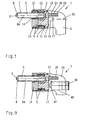
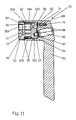
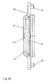
- Fig. 1 of the drawing is an actuator 1 for Espagnolette fittings of windows and doors shown at from a rotary handle shaft 2 a rotary handle 3 protrudes radially, for example.
- the rotary handle shaft 2 contains a coaxial cavity 4 in which a bearing housing 5 is recorded. Through the hollow 4 receives the Rotary handle shaft 2 a substantially bell-like Design. From the bearing housing 5 protrudes downwards Mandrel 6 out in the illustrated embodiment as a rod-shaped, overall with a circumferential toothing 7 provided pinion is formed. The free end 8 of the Rotary mandrel 6 runs out in a cylindrical pin 9.
- the axis of rotation 6a of the mandrel 6 has a relative according to FIG. 1 to the axis of rotation 2a of the rotary handle shaft 2 parallel offset arrangement in the bearing housing 5.
- the free End 8 facing away from end 10 of the mandrel 6 is in one Upper housing part 11 of the bearing housing 5 also as cylindrical pin 22 rotatably mounted.
- the bearing housing 5 is, as can be seen in Fig. 1, almost completely from the coaxial cavity 4 at the free end of the bell-like designed rotary handle shaft 2 added.
- the coaxial cavity 4 of the rotary handle shaft 2 is below closed by a bottom 13 of the bearing housing 5, the has a through hole 14 in which a Cross section of the shape of the mandrel 6 adapted bearing element 15 rotatably supports the mandrel 6.
- the upper housing part 11 of the Bearing housing 5 projects with a pin 16 into a bore 17 the roof 18 of the coaxial cavity 4 centering into it.
- Upper housing part 11 and housing base 13 are rotationally fixed, for. B. connected by screws or rivets.
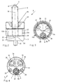
- Fig. 2 shows the bearing housing 5 with the protruding therefrom Mandrel 6 and the toothed ring 12 with internal teeth 12a in on an enlarged scale. It can be clearly seen how the bearing element 15 engages around the rotating mandrel 6 and is rotatable is mounted in the housing base 13. It is of the type and Design of the mandrel 6 depends on whether the bearing sleeve 15th with a positive plug connection to the turning mandrel 6 is executed, or whether the bearing sleeve in the housing 13 is seated in a rotationally fixed manner and the mandrel 6 in the bearing sleeve 15 is rotatably mounted.
- the mandrel 6 where the bearing element 15 with it in Contact occurs has a cylindrical cross section.
- the toothed ring 12 provided with the internal toothing 12a is as annular element between the housing base 13 and the upper housing part 11 rotatably arranged. He's going to assembly in the cavity 4 of - in this illustration omitted - rotary handle shaft 2 pressed so that both parts are non-rotatably connected. Since the Toothed ring 12 rotatable, but structurally with the Bearing housing 5 is united, that is also about him Bearing housing 5 in the cavity 4 of the rotary handle shaft 2 held.
- the upper housing part 11 contains one for the cylindrical Pin 22 formed end 10 of the mandrel 6 as storage serving bore 23. Between the upper housing part 11 and the Toothed ring 12 is also a spacer 24 which the relative rotation of the toothed ring 12 and the bearing housing 5 relieved to each other.
- Actuating device 1 The function of those described above Actuating device 1 can be seen from FIGS. 1 to 3 comprehend.
- the rotary handle shaft 2 is manually over, for example the rotary handle 3 rotated. Since the toothed ring 12 sits in the cavity 4 of the rotary handle shaft 2 in a rotationally fixed manner, for example, by connecting the two parts together knurling on the outside of the toothed ring 12, it will inevitably turned. Over the upper housing part 11 and over the bearing 16 is centered in the bearing housing 5 coaxial cavity 4 added. Between the housing base 13 and Upper housing part 11, the mandrel 6 is rotatably mounted and engages with its external toothing in the internal toothing 12a of the ring gear 12. According to the Diameter ratios of the pitch circle 25 of the toothed ring 12 to the pitch circle 26 of the mandrel 6, the angle of rotation - Turning handle 3 and the turning mandrel - not visible here 6 translated.
- Fig. 4 shows the bottom view of the bearing housing 5 with the Housing base 13, which is penetrated by the mandrel 6.
- the mandrel 6 is in the housing base 13 by the Bearing element 15 rotatably mounted.
- the bearing element 15 to connect rotationally fixed to the mandrel 6, for example by Positive locking with the circumferential toothing 7.
- the housing base 13 preferably also contains two threaded holes 29 which to attach the entire actuator 1 on Sashes of a window or a door can be used.
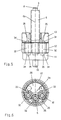
- FIG. 5 and 6 show another embodiment of a Actuating device 1.
- toothed ring 12 and mandrel 6 additionally switched intermediate wheels 32.
- the Mandrel 6 therefore does not mesh directly with the Internal toothing 12a of the toothed ring 12, but indirectly via the intermediate wheels 32.
- at appropriate selection of the dimension of the intermediate wheels 32 die Axial position of the turning mandrel 6 relative to the axis of the turning handle shaft 2 can be varied within certain limits without that the gear ratio between gear ring 12 and Mandrel 6 changes.
- the one immersed in the toothed ring 12 Projection 28 is in each of the intermediate wheels 32 neighboring area with an almost quarter-circular Provide indentation 33.
- the intermediate wheels 32 each have at their ends cylindrical spigot 34 that fit into storage Bores 35 of the upper housing part 11 and the housing base 13 sit in.
- the partial circles 26 are correct of the mandrel 6 and the intermediate wheels 32 so that both the intermediate wheels 32 and the mandrel 6 from the Have the same externally toothed profile material manufactured.
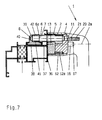
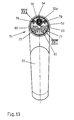
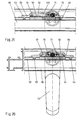
- Fig. 7 shows an actuator 1 on one Wing profile 36 mounted.
- the bearing housing 5 is almost completely in the coaxial cavity 4 of the rotary handle shaft 2 a.
- the internally toothed toothed ring 12 is in non-rotatable connection with the rotary handle shaft 2. You is, for example, by knurling the outer circumference of the Toothed ring 12 reached in the cavity 4 of the Rotary handle shaft 2 is pressed.
- the bearing housing 5 is housed in the rotary handle shaft 2 relatively rotatable.
- the toothed ring 12 and the bearing housing 5 are centered indirectly over the pin 16 of the bearing housing 5, by this in an axial to the central axis of the coaxial Cavity 4 running hole 17 is immersed.
- the gear ring 12 meshes with its internal toothing 12a with the toothing 7 of the Rotary mandrel 6, which is rotatable in the upper housing part 11 and in Housing bottom 13 is mounted.
- the mandrel 6 penetrates the Visible surface of the wing 36 and ends above one at the Sash rebate surface 37 provided, undercut groove 38.
- the undercut groove 38 is, for. B. C-shaped and limited takes a drive rod in it.
- the actuating device 1 is a Coupling tab 39 associated with the - not shown - connecting rod is connected.
- the Coupling strap 39 engages around the free end 8 of the rotating mandrel 6 the operating device 1 and supports its cylindrical Pin 9 in a receptacle 40.
- the lower, parallel to Wing rebate surface 37 extending inner surface 41 of the Coupling tab 39 is with a suitable for the toothing 7 of the Rotary mandrel 6 provided teeth 41, so that these interlock to rotate the mandrel 6 in implement a linear movement of the coupling plate 39.
- the upper surface parallel to the sash rebate surface 37 The coupling tab 6, however, is a smooth surface 42 educated.
- the receptacle 40 of the Coupling tab 39 advantageously as an elongated depression formed because the coupling tab 39 relative to - not shown here - shovel 6 moves.
- the Coupling tab 39 is by means of the downward Pin 43 with the drive rod of the drive rod fitting detachable.
- the toothing 41 is also conceivable for the toothing 41 to be made of the same material with the drive rod. As well it is possible to pin 9 at the free end 8 of the mandrel 6th the actuator 1 by a fixed in the wing installed - behind the undercut groove 39 to store - fixed bearing block.
- the clutch tab In this case, 39 is only with the toothing 41 to convert the rotational movement of the mandrel 6 in the Translational movement of the longitudinally displaceable drive rod fitted.
- mandrel 6 with a in the fold arranged drive rod gear cooperates, which from a gear meshing with the drive rod, which with the mandrel 6 is in rotation and in a housing is stored.
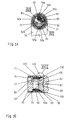
- Fig. 9 still shows an actuator 1 for Securing certain switch positions additionally a lock 46 contains.
- the lock 46 locks the rotary handle shaft 2 relative to the upper housing part 11 of the bearing housing 5 by it with a projection 47 into one - only in FIG. 10 shown - recess 48 of the upper housing part 11 can be indented.
- the lock 46 can be key-operated or by a locking mechanism operated so that the key only for unlocking of the lock is needed.
- a so-called cylinder lock 46 used.
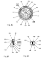
- FIG. 10 shows the upper housing part 11 of the bearing housing 5 the pin 16 for centering the same in the rotary handle shaft 2.
- the recesses 48 can also be seen Engaging the protrusion 47 of the lock shown in FIG. 9 46.
- This view also shows clearly how the Locking interventions 49 are arranged with the - here also not visible - locking ball 21 the different Lock the switch positions of the operating device 1.
- the Locking interventions 49 are in the form of troughs which are open at the side Housing upper part 11 introduced, with the right and left Usability of the actuator four 90 ° positions each available. To achieve more fixed Switching positions can be provided for additional locking interventions become.
- Actuator 51 is based on its basic principle with the actuating device 1 according to FIGS. 1 to 10 match. Therefore, the corresponding ones Functional parts of the actuating device 51 according to FIG. 11 to 20 provided with reference numbers which are compared to the corresponding reference numbers for the actuator 1 1 to 10 are each increased by the value 50.
- actuator 51 for Espagnolette fittings for windows and doors stands from a rotary handle shaft 52 Turning handle 53 essentially radially.
- the bell gets an approximately bell-like design
- Rotary handle shaft 52 through a coaxial cavity 54 in the a bearing housing 55 is received.
- a mandrel 56 which as a rod-shaped, pinion provided with a total of 57 teeth can be executed.
- the free end 58 of this mandrel 56 runs out into a cylindrical pin 59.
- His Rotation axis 56a has a relative to FIGS. 12 and 14 Rotation axis 52a of the rotary handle shaft 52 offset in parallel Arrangement in the bearing housing 55. That in the bearing housing 55 located end 60 of the mandrel 56 is also as cylindrical pin 72 designed and rotatable by one Bore 73 in the upper housing part 61 of the bearing housing 55 added.
- Coupling surfaces 62b and mating coupling surfaces 54a arise simple interlocking engagement with each other, when bearing housing 55 and gear ring 62 axially together in the coaxial cavity 54 of the rotary handle shaft 52 be inserted.
- the toothed ring 62 comes along the rotary handle shaft 52 in non-rotatable connection while at the same time the bearing housing 5 is relatively rotatable in the coaxial Cave 54 is added.
- the axial position fixation of the toothed ring 62 and the Bearing housing 55 in the coaxial cavity 54 of the Rotary handle shaft 52 are special snap hooks 100 useful. At least they engage from the toothed ring 62 in regions on the circumference of the upper housing part 61 in the form of Reach past ring segments.
- the snap hooks 100 act doing so with annular groove undercuts 101 on the inner circumference of the coaxial cavity 54 of the rotary handle shaft 52 together, by being elastic in this direction radially outward engage (see Fig. 16).
- the arrangement and training of the Snap hook 100 is particularly clear in FIGS. 16 to 18 to see the drawing.
- the ring body 103 and the Snap hook 100 together a one-piece plastic molding, that is stable enough to support the axial Secure the position of the bearing housing 55 and gear ring 62 in the To ensure cavity 54 of the rotary handle shaft 52.
- Fig. 15 can still be seen that it can be expedient, the secantial Coupling surfaces 62b on the outer circumference of the toothed ring 62 and / or also the complementary mating coupling surfaces 54a in FIG coaxial cavity 54 of the rotary handle shaft 52 with linear profiles of low height, for example with triangular teeth.
- these can as play switching elements between the coupling surfaces 62b and the counter coupling surfaces 54a act when they are in the axially plugging the rotary handle shaft 52 with the Bearing housing 55 and the gear ring 62 meet and more or less of a remaining deformation be subjected.
- FIGS. 11 and 12 of the drawing show that it can also be advantageous if the mandrel 56 over its entire length is profiled as a pinion. She leaves namely both with the toothing 91 on the wing 86 in the undercut groove 88 of the sash rebate surface 87 slidably guided coupling tab 89 as well as either with the internal toothing 62a of the toothed ring 62 or with the intermediate pinion 82 of the transmission gear on simple Bring it in a releasable axial connector.
- the mandrel 56 not only passes through the through hole 64 in the case bottom 63, but it is also from that in this Through bore 64 of the same, sleeve-shaped Bearing element 65 added. If the latter rotates in the through hole 64 is seated, it is advantageous to its Inner contour complementary to the pinion profile of the mandrel 56 design so that it can include this form-fitting.
- Threaded bores 79 in the housing base 63 of the bearing housing 55 can be brought into cover position, so that in each case Fastening screw can be screwed in. This leaves the entire actuator 51 with a window and Bring door leaf 86 into a secure holding connection.
- the actuating device 1 or 51 also in connection with espagnolette fittings for Use where the drive rods can be slid longitudinally guided on the back of a so-called faceplate become.
- the faceplate is the Attachment of the connecting rod fitting in a so-called Step groove (Euro groove) is useful, which then - instead the undercut groove - in the sash rebate 37 or 87 is located.
- Step groove Euro groove
Landscapes
- Engineering & Computer Science (AREA)
- Mechanical Engineering (AREA)
- Lock And Its Accessories (AREA)
- Walking Sticks, Umbrellas, And Fans (AREA)
- Wing Frames And Configurations (AREA)
- Exhaust-Gas Circulating Devices (AREA)
- Massaging Devices (AREA)
- Buildings Adapted To Withstand Abnormal External Influences (AREA)
- Valve Device For Special Equipments (AREA)
- Fluid-Driven Valves (AREA)
- Actuator (AREA)
Applications Claiming Priority (2)
| Application Number | Priority Date | Filing Date | Title |
|---|---|---|---|
| DE19531680 | 1995-08-29 | ||
| DE19531680A DE19531680C1 (de) | 1995-08-29 | 1995-08-29 | Betätigungsvorrichtung |
Publications (2)
| Publication Number | Publication Date |
|---|---|
| EP0763641A1 EP0763641A1 (de) | 1997-03-19 |
| EP0763641B1 true EP0763641B1 (de) | 1999-08-25 |
Family
ID=7770625
Family Applications (1)
| Application Number | Title | Priority Date | Filing Date |
|---|---|---|---|
| EP96112239A Expired - Lifetime EP0763641B1 (de) | 1995-08-29 | 1996-07-29 | Betätigungsvorrichtung |
Country Status (9)
| Country | Link |
|---|---|
| EP (1) | EP0763641B1 (hu) |
| AT (1) | ATE183804T1 (hu) |
| CZ (1) | CZ290620B6 (hu) |
| DE (2) | DE19531680C1 (hu) |
| ES (1) | ES2138277T3 (hu) |
| HU (1) | HU218440B (hu) |
| PL (1) | PL180207B1 (hu) |
| SK (1) | SK110496A3 (hu) |
| TR (1) | TR199600693A2 (hu) |
Cited By (2)
| Publication number | Priority date | Publication date | Assignee | Title |
|---|---|---|---|---|
| EP1462594B2 (de) † | 2003-02-25 | 2012-11-21 | Roto Frank Ag | Getriebe, insbesondere Schlagleistengetriebe für ein Fenster oder dergleichen |
| US11298754B1 (en) * | 2020-05-20 | 2022-04-12 | National Technology & Engineering Solutions Of Sandia, Llc | Mode I fracture testing fixture |
Families Citing this family (10)
| Publication number | Priority date | Publication date | Assignee | Title |
|---|---|---|---|---|
| DE10162707A1 (de) * | 2001-12-19 | 2003-07-10 | Roto Frank Ag | Drehbetätigungseinrichtung für ein Schaltgetriebe an einem Flügel oder einem festen Rahmen eines Fensters, einer Tür od. dgl. |
| FR2865493B1 (fr) * | 2004-01-28 | 2007-08-24 | Croisee Ds | Systeme permettant d'entrainer au moyen d'une poignee la rotation d'un arbre de commande d'une cremone ou analogue |
| DE102004006653A1 (de) * | 2004-02-11 | 2005-09-01 | Aug. Winkhaus Gmbh & Co. Kg | Antriebseinrichtung für einen Treibstangenbeschlag |
| DE102004044796A1 (de) * | 2004-09-16 | 2006-04-06 | Roto Frank Ag | Griffanordnung |
| FR2923252A1 (fr) * | 2007-11-02 | 2009-05-08 | Ferco Int Usine Ferrures | Dispositif d'entrainement pour ferrure de verrouillage de type cremone ou cremone-serrure |
| CN106574473B (zh) * | 2014-06-27 | 2019-06-04 | Gsg国际股份有限公司 | 门或窗的把手 |
| CN106661898B (zh) * | 2014-06-27 | 2019-06-04 | Gsg国际股份有限公司 | 门或窗的把手 |
| ITUB20153315A1 (it) * | 2015-09-01 | 2017-03-01 | Opera S R L | Maniglia per serrature, particolarmente di tipo antipanico. |
| IT201800010575A1 (it) * | 2018-11-26 | 2020-05-26 | Fapim S P A | Maniglia per serramenti |
| FR3091891B1 (fr) * | 2019-01-23 | 2022-06-17 | Ferco | Système de poignée symétrique à démultiplication |
Family Cites Families (4)
| Publication number | Priority date | Publication date | Assignee | Title |
|---|---|---|---|---|
| FR425393A (fr) * | 1910-02-05 | 1911-06-09 | Otto Kublanck | Fermeture pour portes de secours avec verrous à bascule déclenchés au moyen d'une barre transversale |
| DE1272161B (de) * | 1966-12-07 | 1968-07-04 | Jaeger Frank K G | Getriebe eines Treibstangenbeschlages fuer Fenster, Tueren od. dgl., insbesondere fuer Kipp-Schwenkfluegel-Fenster |
| DE1275910B (de) * | 1966-12-24 | 1968-08-22 | Jaeger Frank K G | Getriebe eines Treibstangenbeschlages fuer Fenster, Tueren od. dgl., insbesondere fuer Kipp-Schwenkfluegel-Fenster |
| DE2515989A1 (de) * | 1975-04-12 | 1976-10-21 | Stucke Lothar | Kantengetriebe fuer ein fenster, eine tuer o.dgl. |
-
1995
- 1995-08-29 DE DE19531680A patent/DE19531680C1/de not_active Expired - Fee Related
-
1996
- 1996-07-29 AT AT96112239T patent/ATE183804T1/de not_active IP Right Cessation
- 1996-07-29 EP EP96112239A patent/EP0763641B1/de not_active Expired - Lifetime
- 1996-07-29 DE DE59602859T patent/DE59602859D1/de not_active Expired - Fee Related
- 1996-07-29 ES ES96112239T patent/ES2138277T3/es not_active Expired - Lifetime
- 1996-08-08 HU HU9602184A patent/HU218440B/hu not_active IP Right Cessation
- 1996-08-14 PL PL96315706A patent/PL180207B1/pl unknown
- 1996-08-26 CZ CZ19962516A patent/CZ290620B6/cs not_active IP Right Cessation
- 1996-08-27 SK SK1104-96A patent/SK110496A3/sk unknown
- 1996-08-29 TR TR96/00693A patent/TR199600693A2/xx unknown
Cited By (2)
| Publication number | Priority date | Publication date | Assignee | Title |
|---|---|---|---|---|
| EP1462594B2 (de) † | 2003-02-25 | 2012-11-21 | Roto Frank Ag | Getriebe, insbesondere Schlagleistengetriebe für ein Fenster oder dergleichen |
| US11298754B1 (en) * | 2020-05-20 | 2022-04-12 | National Technology & Engineering Solutions Of Sandia, Llc | Mode I fracture testing fixture |
Also Published As
| Publication number | Publication date |
|---|---|
| CZ290620B6 (cs) | 2002-09-11 |
| CZ251696A3 (en) | 1997-03-12 |
| TR199600693A2 (tr) | 1997-03-21 |
| SK110496A3 (en) | 1997-04-09 |
| HUP9602184A2 (en) | 1997-03-28 |
| DE59602859D1 (de) | 1999-09-30 |
| ATE183804T1 (de) | 1999-09-15 |
| HU9602184D0 (en) | 1996-09-30 |
| ES2138277T3 (es) | 2000-01-01 |
| DE19531680C1 (de) | 1996-08-01 |
| PL315706A1 (en) | 1997-03-03 |
| PL180207B1 (pl) | 2001-01-31 |
| HU218440B (hu) | 2000-08-28 |
| HUP9602184A3 (en) | 1999-10-28 |
| EP0763641A1 (de) | 1997-03-19 |
Similar Documents
| Publication | Publication Date | Title |
|---|---|---|
| EP0763641B1 (de) | Betätigungsvorrichtung | |
| EP0589170B1 (de) | Treibstangenbeschlag für Fenster, Türen od. dgl. | |
| WO1998042938A1 (de) | Hebelverschluss | |
| EP0004325B1 (de) | Getriebe für Fenster- und Türverschlüsse od. dgl. | |
| EP0260517B1 (de) | Betätigungshandhabe, insbesondere Fenstergriff | |
| DE3504691C2 (hu) | ||
| EP2058461B1 (de) | Treibstangengetriebe | |
| EP1359273B1 (de) | Verriegelungsbeschlag an einem Fenster, einer Tür oder dergleichen, mit gegenläufig verschiebbaren Treibstangen | |
| DE3718173C2 (hu) | ||
| EP0440987B2 (de) | Treibstangengetriebe | |
| EP1216335B1 (de) | Zwischengetriebe für fenster-oder türbeschlag | |
| EP0823523A2 (de) | Einsteckgetriebe für die Betätigung der Treibstangenbeschläge an Fenstern, Türen od. dgl. | |
| DE4040302C2 (de) | Betätigungsgetriebe für Fenster- und Türverschlüsse o. dgl. | |
| EP0784142B1 (de) | Betätigungsgetriebe für Fenster und/oder Türbeschläge mit Stell- und/oder Verriegelungsgestänge od. dgl. | |
| DE3937817A1 (de) | Sperrbares getriebe fuer fensterbeschlaege | |
| EP0728888A1 (de) | Schnäpper für eine Drehkipptür | |
| DE3317264C2 (hu) | ||
| EP1671001B1 (de) | Schloss | |
| DE102010055397B4 (de) | Verriegelungs-/Entriegelungsvorrichtung für eine Schiebetür und mit einer solchen Vorrichtung ausgestattete Tür | |
| EP2218849A2 (de) | Handhabe für Dreh-Kipp-Fenster und Dreh-Kipp-Türen | |
| AT509464B1 (de) | Schloss | |
| DE1275910B (de) | Getriebe eines Treibstangenbeschlages fuer Fenster, Tueren od. dgl., insbesondere fuer Kipp-Schwenkfluegel-Fenster | |
| EP1566509B1 (de) | Adapter sowie Verbindungselement für ein Beschlaggetriebe sowie Beschlaggetriebe für ein Fenster, eine Tür oder dergleichen | |
| EP1211371A1 (de) | Profilrahmen mit Verschlussgetriebe | |
| EP0752509B1 (de) | Abschliessbarer Betätigungsgriff für Fenster, Türe oder dergleichen |
Legal Events
| Date | Code | Title | Description |
|---|---|---|---|
| PUAI | Public reference made under article 153(3) epc to a published international application that has entered the european phase |
Free format text: ORIGINAL CODE: 0009012 |
|
| AK | Designated contracting states |
Kind code of ref document: A1 Designated state(s): AT BE CH DE DK ES FI FR GB IT LI NL SE |
|
| AX | Request for extension of the european patent |
Free format text: LT PAYMENT 960729;SI PAYMENT 960729 |
|
| 17P | Request for examination filed |
Effective date: 19970402 |
|
| GRAG | Despatch of communication of intention to grant |
Free format text: ORIGINAL CODE: EPIDOS AGRA |
|
| GRAG | Despatch of communication of intention to grant |
Free format text: ORIGINAL CODE: EPIDOS AGRA |
|
| GRAH | Despatch of communication of intention to grant a patent |
Free format text: ORIGINAL CODE: EPIDOS IGRA |
|
| 17Q | First examination report despatched |
Effective date: 19990209 |
|
| GRAH | Despatch of communication of intention to grant a patent |
Free format text: ORIGINAL CODE: EPIDOS IGRA |
|
| ITF | It: translation for a ep patent filed |
Owner name: DE DOMINICIS & MAYER S.R.L. |
|
| GRAA | (expected) grant |
Free format text: ORIGINAL CODE: 0009210 |
|
| AK | Designated contracting states |
Kind code of ref document: B1 Designated state(s): AT BE CH DE DK ES FI FR GB IT LI NL SE |
|
| AX | Request for extension of the european patent |
Free format text: LT PAYMENT 19960729;SI PAYMENT 19960729 |
|
| PG25 | Lapsed in a contracting state [announced via postgrant information from national office to epo] |
Ref country code: SE Free format text: THE PATENT HAS BEEN ANNULLED BY A DECISION OF A NATIONAL AUTHORITY Effective date: 19990825 Ref country code: FI Free format text: LAPSE BECAUSE OF NON-PAYMENT OF DUE FEES Effective date: 19990825 |
|
| REF | Corresponds to: |
Ref document number: 183804 Country of ref document: AT Date of ref document: 19990915 Kind code of ref document: T |
|
| REG | Reference to a national code |
Ref country code: CH Ref legal event code: NV Representative=s name: PATENTANWAELTE GEORG ROEMPLER UND ALDO ROEMPLER Ref country code: CH Ref legal event code: EP |
|
| GBT | Gb: translation of ep patent filed (gb section 77(6)(a)/1977) |
Effective date: 19990827 |
|
| REF | Corresponds to: |
Ref document number: 59602859 Country of ref document: DE Date of ref document: 19990930 |
|
| PG25 | Lapsed in a contracting state [announced via postgrant information from national office to epo] |
Ref country code: DK Free format text: LAPSE BECAUSE OF FAILURE TO SUBMIT A TRANSLATION OF THE DESCRIPTION OR TO PAY THE FEE WITHIN THE PRESCRIBED TIME-LIMIT Effective date: 19991125 |
|
| REG | Reference to a national code |
Ref country code: ES Ref legal event code: FG2A Ref document number: 2138277 Country of ref document: ES Kind code of ref document: T3 |
|
| ET | Fr: translation filed | ||
| PLBE | No opposition filed within time limit |
Free format text: ORIGINAL CODE: 0009261 |
|
| STAA | Information on the status of an ep patent application or granted ep patent |
Free format text: STATUS: NO OPPOSITION FILED WITHIN TIME LIMIT |
|
| PGFP | Annual fee paid to national office [announced via postgrant information from national office to epo] |
Ref country code: AT Payment date: 20000718 Year of fee payment: 5 |
|
| PGFP | Annual fee paid to national office [announced via postgrant information from national office to epo] |
Ref country code: CH Payment date: 20000802 Year of fee payment: 5 |
|
| 26N | No opposition filed | ||
| PG25 | Lapsed in a contracting state [announced via postgrant information from national office to epo] |
Ref country code: AT Free format text: LAPSE BECAUSE OF NON-PAYMENT OF DUE FEES Effective date: 20010729 |
|
| PG25 | Lapsed in a contracting state [announced via postgrant information from national office to epo] |
Ref country code: LI Free format text: LAPSE BECAUSE OF NON-PAYMENT OF DUE FEES Effective date: 20010731 Ref country code: CH Free format text: LAPSE BECAUSE OF NON-PAYMENT OF DUE FEES Effective date: 20010731 |
|
| REG | Reference to a national code |
Ref country code: GB Ref legal event code: IF02 |
|
| REG | Reference to a national code |
Ref country code: CH Ref legal event code: PL |
|
| PGFP | Annual fee paid to national office [announced via postgrant information from national office to epo] |
Ref country code: GB Payment date: 20040621 Year of fee payment: 9 |
|
| PGFP | Annual fee paid to national office [announced via postgrant information from national office to epo] |
Ref country code: BE Payment date: 20040727 Year of fee payment: 9 |
|
| PGFP | Annual fee paid to national office [announced via postgrant information from national office to epo] |
Ref country code: ES Payment date: 20050706 Year of fee payment: 10 |
|
| PGFP | Annual fee paid to national office [announced via postgrant information from national office to epo] |
Ref country code: FR Payment date: 20050713 Year of fee payment: 10 |
|
| PGFP | Annual fee paid to national office [announced via postgrant information from national office to epo] |
Ref country code: NL Payment date: 20050715 Year of fee payment: 10 |
|
| PG25 | Lapsed in a contracting state [announced via postgrant information from national office to epo] |
Ref country code: GB Free format text: LAPSE BECAUSE OF NON-PAYMENT OF DUE FEES Effective date: 20050729 |
|
| PG25 | Lapsed in a contracting state [announced via postgrant information from national office to epo] |
Ref country code: BE Free format text: LAPSE BECAUSE OF NON-PAYMENT OF DUE FEES Effective date: 20050731 |
|
| GBPC | Gb: european patent ceased through non-payment of renewal fee |
Effective date: 20050729 |
|
| PGFP | Annual fee paid to national office [announced via postgrant information from national office to epo] |
Ref country code: IT Payment date: 20060731 Year of fee payment: 11 Ref country code: DE Payment date: 20060731 Year of fee payment: 11 |
|
| PG25 | Lapsed in a contracting state [announced via postgrant information from national office to epo] |
Ref country code: NL Free format text: LAPSE BECAUSE OF NON-PAYMENT OF DUE FEES Effective date: 20070201 |
|
| NLV4 | Nl: lapsed or anulled due to non-payment of the annual fee |
Effective date: 20070201 |
|
| REG | Reference to a national code |
Ref country code: FR Ref legal event code: ST Effective date: 20070330 |
|
| REG | Reference to a national code |
Ref country code: ES Ref legal event code: FD2A Effective date: 20060731 |
|
| BERE | Be: lapsed |
Owner name: *SIEGENIA-FRANK K.G. Effective date: 20050731 |
|
| PG25 | Lapsed in a contracting state [announced via postgrant information from national office to epo] |
Ref country code: ES Free format text: LAPSE BECAUSE OF NON-PAYMENT OF DUE FEES Effective date: 20060731 |
|
| PG25 | Lapsed in a contracting state [announced via postgrant information from national office to epo] |
Ref country code: FR Free format text: LAPSE BECAUSE OF NON-PAYMENT OF DUE FEES Effective date: 20060731 Ref country code: DE Free format text: LAPSE BECAUSE OF NON-PAYMENT OF DUE FEES Effective date: 20080201 |
|
| PG25 | Lapsed in a contracting state [announced via postgrant information from national office to epo] |
Ref country code: IT Free format text: LAPSE BECAUSE OF NON-PAYMENT OF DUE FEES Effective date: 20070729 |