EP0761423A2 - Verfahren zum Verdichten von Pulver - Google Patents
Verfahren zum Verdichten von Pulver Download PDFInfo
- Publication number
- EP0761423A2 EP0761423A2 EP96114412A EP96114412A EP0761423A2 EP 0761423 A2 EP0761423 A2 EP 0761423A2 EP 96114412 A EP96114412 A EP 96114412A EP 96114412 A EP96114412 A EP 96114412A EP 0761423 A2 EP0761423 A2 EP 0761423A2
- Authority
- EP
- European Patent Office
- Prior art keywords
- air
- guide
- powder
- rubber mold
- packing
- Prior art date
- Legal status (The legal status is an assumption and is not a legal conclusion. Google has not performed a legal analysis and makes no representation as to the accuracy of the status listed.)
- Granted
Links
Images


Classifications
-
- B—PERFORMING OPERATIONS; TRANSPORTING
- B30—PRESSES
- B30B—PRESSES IN GENERAL
- B30B15/00—Details of, or accessories for, presses; Auxiliary measures in connection with pressing
- B30B15/02—Dies; Inserts therefor; Mounting thereof; Moulds
- B30B15/022—Moulds for compacting material in powder, granular of pasta form
- B30B15/024—Moulds for compacting material in powder, granular of pasta form using elastic mould parts
-
- B—PERFORMING OPERATIONS; TRANSPORTING
- B22—CASTING; POWDER METALLURGY
- B22F—WORKING METALLIC POWDER; MANUFACTURE OF ARTICLES FROM METALLIC POWDER; MAKING METALLIC POWDER; APPARATUS OR DEVICES SPECIALLY ADAPTED FOR METALLIC POWDER
- B22F3/00—Manufacture of workpieces or articles from metallic powder characterised by the manner of compacting or sintering; Apparatus specially adapted therefor ; Presses and furnaces
- B22F3/004—Filling molds with powder
-
- B—PERFORMING OPERATIONS; TRANSPORTING
- B30—PRESSES
- B30B—PRESSES IN GENERAL
- B30B11/00—Presses specially adapted for forming shaped articles from material in particulate or plastic state, e.g. briquetting presses, tabletting presses
- B30B11/02—Presses specially adapted for forming shaped articles from material in particulate or plastic state, e.g. briquetting presses, tabletting presses using a ram exerting pressure on the material in a moulding space
- B30B11/027—Particular press methods or systems
-
- B—PERFORMING OPERATIONS; TRANSPORTING
- B30—PRESSES
- B30B—PRESSES IN GENERAL
- B30B15/00—Details of, or accessories for, presses; Auxiliary measures in connection with pressing
- B30B15/30—Feeding material to presses
- B30B15/302—Feeding material in particulate or plastic state to moulding presses
Definitions
- the present invention relates to a packing method in which a powder, a granular material, a material in flakes, a plate material or the like is injected into a container or receptacle such as a can, a bag, a rubber mold, a die or the like which has an opening for feeding the material and a space of which is filled with said powder or the like.
- a container or receptacle such as a can, a bag, a rubber mold, a die or the like which has an opening for feeding the material and a space of which is filled with said powder or the like.
- a packing method has been known in which a space with an opening for injecting a material is filled with the material, and the material is pressed with a pressing device such as pusher or the like, thereby packing the space with the material more compacted.
- Another packing method has also been known in which the injected material is mechanically vibrated or tapped, thereby filling the space with the material more compacted.
- Another problem of the conventional methods is that applying mechanical vibration or tapping to the die or the container, to the device to hold them, or to the apparatus, or to the table for conveying the die or the container causes to damage those devices and shorten their durable years.
- pressing the material packed in the space leads to the difference in the packing-density between the region near the pressing device and the region distant from the pressing device, because the material in the region away from the pressing device receives a pressing force weaker than that in the vicinity of the pressing device. Therefore, it cannot ensure a packing with a uniform packing-density. This is especially a problem when packing the material into a long and narrow space. If a rubber mold is filled with a powder as the material with uneven packing densities and pressed as it is with punches or by hydrostatic pressing, the resultant compact is likely to have distortion in shape or to crack or to chip. Furthermore, an unevenly filled container can contain only an insufficient, small quantity of the material, which means that the space of the container is not fully used. In spite of many demands in the industry for uniform and highly densified packing, it has been difficult for the conventional packing methods to satisfy those demands.
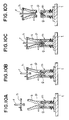
- Figure 1 is a prespective view of a part produced by subjecting a compact after pressing to a process such as sintering.
- Figure 2 is a vertical sectional view of a split die and a guide etc. for producing a compact in which the packing method of the present invention is adopted.
- Figure 3 is a vertical sectional view of a die and a guide etc. for producing a cylindrical compact in which the packing method of the present invention is adopted.
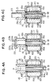
- Figure 4 is a vertical sectional view of a dry hydrostatic pressing apparatus in which the packing method of the present invention is adopted.
- Figure 5 is a vertical sectional view of an granulation apparatus in which the packing method of the present invention is adopted.
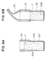
- Figire 6 is a vertical sectional view of a packing apparatus for flaky materials in which the packing method of the present invention is adopted.
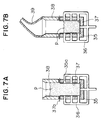
- Figure 7 is a vertical sectional view of a packing apparatus for packing materials into a bag in which the packing method of the present invention adopted.
- Figure 8 is a vertical sectional view of a packing apparatus for packing a powder into a split rubber mold in which the packing method of the present is adopted.
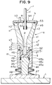
- Figure 9 is a vertical sectional view of a packing apparatus having a mold device in which the packing method of the present invention is adopted.
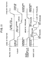
- Figure 10 is the packing process of the packing apparatus shown in Figure 9.
- Figure 11 is an operational diagram showing relatively the movements of the main parts of the packing apparatus shown in Figures 10 and 11.
- a part (w) shown in Figure 1 forms an integrated body comprising a spur gear (2) which is formed around the middle of axis (1) and a bevel gear (3) formed at the end of axis (1).
- the method for producing a green compact for the part (w) by using a split die is hereinafter described.
- a split die (4) is assembled with two parts (4a),(4b) by bringing each vertical surface into contact, and the assembled split die (4) is provided with an opening (4c) on its top.
- a space part (4d) which is filled with powder (p) is designed intending for the part (w) taking the dimensional change after sintering into account.
- a guide (5) is placed upon the split die (4).
- the diameter of the hole (5a) of the guide (5) is the same as or smaller than the diameter of the opening (4c) of the split die (4).
- the upper end of the hole (5a) should preferably form a slope as indicated by (5b).
- the cover element (6) is placed upon the guide(5) so that it seals the guid (5).
- the cover element (6) is provided with an appropriate number of holes (6a) which are connected with connecting pipes (6b).
- the connecting pipes (6b) are connected with a pumping device such as an ejector-type vacuum generator which is not shown in the drawing.
- the pumping device is actuated to let air out of the space part (4d) of the split die (4) and the hole (5a) of the guide (5) so that the space comprising the space part (4d) of the split die (4) and the hole (5a) of the guide (5) is brought into a low air-pressure state.
- the air contained in powder (p) is ejected.
- the air-pressure flowing into the pumping device such as the ejector-type vacuum generator is cut, and air is introduced through the hole (6a) of the cover element (6) so that the air-pressure in the space comprising the hole (5a) of the guide (5) and the space part (4d) of the split die (4) becomes high.
- the filling density of powder (p) which fills the space comprising the space part (4d) of split die (4) and hole (5a) of the guide (5) is raised.
- the air-pressure of the space comprising the space part (4d) of the split die 4 and the hole (5a) of the guide (5) from a low air-pressure state to a high air-pressure state appropriate times, the air contained in the powder (p) is evacuated as well as most of the powder (p) in the hole (5a) of the guide (5) is packed into the space part (4d) of the split die (4).
- the repetition of switching the state of the space from the low air-pressure to the high air-pressure is hereinafter simply refferred to as the "air tapping process” or "air tapping".
- air tapping process ensures the high-density packing of the powder (p) into the space part (4d) of the split die (4).
- air tapping process not only air but also various kinds of gases can be used.
- nitrogen gas or argon gas or the like is used.
- the low air-pressure state and the high air-pressure state in the air tapping process mentioned above mean the states of the air-pressure relatively low or high when compared to each other.
- the packing-density of powder (p) is increased when the state is switched from the low air-pressure to the high air-pressure.
- the low air-pressure is in the range of 0.1 to 0.5 atm and the high air-pressure is in the range of 0.6 to 1.0 atm.
- a typical cycle time is in the range of 0.1 to 1 second, and the packing can be completed within 5 to 10 cycles.
- Using the ejector-type vacuum generator mentioned above makes it easy to carry out the air tapping in such a short cycle time. That is, supplying air-pressure into the ejector-type vacuum generator creates the low air-pressure state, and cutting the air supply immediately creates the high air-pressure state, because the previously ejected air flows back into the space when the air supply is cut.
- the air tapping is carried out in a cycle time described above by supplying air-pressure intermittently (by valve operation).
- the cycle time may of course be longer or shorter, as well as the cycles may be repeated more or less times, considering the size and the shape of the space or the flowabillity of the material.
- the space part (4d) of the split die (4) can be efficiently filled with powder (p) in more quantity and with high packing-density.
- the speed of air flow when introducing air into the space comprising the hole (5a) of the guide (5) and the space part (4d) of the split die (4) should be higher than when reducing pressure of the said space to bring it into the low air-pressure state so that the high-density packing of powder (p) can be more efficiently carried out.
- a compact (C) produced through the aforementioned processes is removed from the split die (4) by removing the guide (5), the cover element (6) and the punch (7) as well as by separating the split die (4) into two parts (4a),(4b). Then the compact (C) is subjected to sintering or the like, thereby obtaining the part (W).
- the punch (7) because the whole or almost all of powder (p) in the hole(5a) of the guide (5) is packed into the space part (4d) of the split die (4), the punch (7) needs to descend only a small distance, and therefore, there is little difference in packing-density between the powder (p) in the vicinity of the punch (7) and the powder (p) of the lower region, which results in a compact (C) having a uniform packing-denisy.
- the present invention allows the powder (p) to thoroughly fill the space part (4d) of the split die (4) including its corners by the air tapping, and therefore prevents from producing defective compacts.
- the present invention is very effective as a method to fill a space projecting sideward as shown in Figure 2.
- (8) is a die having a columnar space and (9) is a columnar core placed in the center of the columnar space of the die (8) whose upper end is slightly projected from the upper surface of the die (8).
- (10) is a lower punch inserted into the lower part of the cylindrical space (11) which is formed between the inner peripheral surface of the die (8) and the outer peripheral surface of the columnar core (9).
- the inner peripheral surface of the die (8), the outer peripheral surface of the colunmar core (9) and the lower punch (10) inserted into the lower part of the cylindrical space (11) form a space part (12) having an annular opening (12a).
- (13) is a guide placed on the upper surface of the die (8).
- the hole (13a) of the guide (13) is designed to have a diameter almost same as the diameter of the columnar space of the die (8).
- the upper part of the hole (13a) of the guide (13) should preferably be formed to have an extended, sloped part (13b) so as to facilitate injection of the powder (p).
- the cover element (14) is a cover element to cover and to seal the guide (13).
- a cylindrical upper punch (15) to be inserted into the above mentioned cylindrical space (11) is fit through a sealing device such as an O-ring (not shown in the drawing) in a vertically slidable manner.
- the cover element (14) is provided with an appropriate number of holes (14b) to which connecting pipes (14c) are connected.
- the connecting pipes (14c) are connected with a pumping device such as an ejector-type vacuum generator (not shown in the drawing).
- the powder (p) is injected into the space part (12) and the hole (13a) of the guide (13) to a desired depth from a powder feeding device (not shown in the drawing).
- the guide (13) is covered and sealed with the cover element (14).
- the pumping device is actuated to switch the state of a space comprising the space part (12) and the hole (13a) of the guide (13) from the low air-pressure to the high air-pressure alternately.
- the powder (p) injected into the hole (13a) of the guide (13) is packed into the space part (12).
- the upper punch (15) is not moved during the air tapping process.
- the top of the upper punch (15) is sealed so as to prevent air from going out of the space.
- the clearances between the die (8) and the lower punch (10) and between the core (9) and the lower punch (10) are sealed with a rubber packing or the like for the same purpose. It is necessary for the clearances to be small enough so that it does not prevent the making of the required low air-pressure and high air-pressure states even if air leaks from the clearance.
- the upper punch (15) as a pusher is inserted into the hole (13a) of the guide (13), and the upper punch (15) is further inserted into the cylindrical space part (12) formed between the inner peripheral surface of die (8) and the outer peripheral surface of the core (9), thereby packing all the powder (p) remaining in the hole (13a) of the guide (13) into the space part (12), as well as pressing with the lower punch (10) and the upper punch (15) to produce a powder compact.
- the upper punch (15) and the cover element (14) are removed and when necessary, the guide (13) is removed from the top of the die (8), and subsequently, the lower punch (10) is moved upward to take the produced compact out of the die (8).
- the powder (p) is packed into the deep, cylindrical space part (12) formed by the core (9) and the die (8) and the like, and then pressed with the lower punch (10) and the upper punch (15).
- Most of powders are hardly packed into such a long and thin space part (12) but likely to form bridges, and therefore the depth of the space part (12) should offen be about three times as deep as the end compact. Injecting a powder into such a deep space part (12) is very difficult.
- moving the upper punch (15) and lower punch (10) for such a long distance causes the powder to get caught by clearances, which reduces the productivity of the compact and damages the die etc..
- the powder (p) is packed at a high packing-density prior to the compaction with the upper punch (15) and lower punch (10), therefore the lower and upper punches (10), (15) need to move only a small distance. Accordingly, it does not cause the powder (p) to get caught by clearances and can improve the productivity of the compact and the life of the die etc..
- the pressing force of lower and upper punches (10), (15) does not reach the powder (p) existing in a region distant from the lower and upper punches (10), (15), but concentrates to the powder (p) in the vicinity of the lower and upper punches (10), (15), which results in a partial increase of the packing-density of the powder (p) only in the vicinity of the lower and upper punches (10), (15), leading to a compact with variant packing-densities.
- the present invention affords the whole or almost all of the powder (p) injected in the hole (13a) of the guide (13) to fill the space part (12), only requiring the upper punch (15) and the lower punch (10) to move a small distance. Therefore, the difference in packing-density between in the vicinity of the lower and upper punches (10), (15) and in the region distant from the lower and upper punches (10), (15) is small, and thus the resultant compact has a uniform packing-density.
- One of the great advantages of the packing method of the present invention is that the powder preliminarily weighed pricisely and injected into the die can be fully used without remain to produce a powder compact.
- the resultant compacts are therefore hafe no variance in quality.
- (16) is a pressure vessel comprising a side wall (16a), a top wall (16b) and a bottom wall (16c), and the top wall (16b) and the bottom wall (16c) are provided in each central part with holes (16b'),(16c') respectively.
- a tubular pressure medium element (16d) made from rubber material (hereinafter referred to as " pressure medium element" is applied.
- pressure medium element By the side wall (16a), the top wall (16b), the bottom wall (16c) and the pressure medium element (16d), the space (16e) of the pressure vessel (16) is formed.
- the side wall (16a) is provided with a fluid introducing tubes (16f) from which a fluid is injected into the space (16e).
- the (17) is a cylindrical rubber mold loaded in the pressure medium element (16d) as a pressure medium.
- a core (18) is provided in the center of the rubber mold (17).
- the outer peripheral surface of the core (8) and the inner perpheral surfece of the rubber mold (17) forms a cylindrical space.
- a cylindrical lower punch (19) is inserted into the lower part of the said cylindrical space.
- the outer peripheral surface of the core (18), the inner peripheral surface of the rubber mold (17) and the top surface of the lower punch (19) form an space part (20).
- the top wall (16b) comprises an annular element (16'') which is placed upon the upper end of the rubber mold (17) after the rubber mold (17) is loaded in the pressure medium element (16d).
- (21) is a guide having a hole (21a) and is mounted on the top wall (16b) of the pressure vessel (16).
- a powder feeder (not shown in the drawing) feeds a preliminarily weihghed, appropriate amount of powder (p) into the space part (20) and the hole (21a) of the guide (21) to a desired depth.
- the pressure vessel (16) is filled with a fluid such as oil.
- the guide (21) is covered with a cover element (22) so as to seal the space comprising the space part (20) and the hole (21a) of the guide (21).
- the cover element (22) is provided with an appropriate number of holes (22a) to which connecting pipes (22b) are connected.
- the connecting pipes (22b) are connected to the pumping device (not shown in the drawing).
- the fluid is further injected from the fluid introducing tube (16f) into the pressure vessel (16) so that the pressure is applied from outside to the rubber mold (17) to compact the powder (p) in the space part (20).
- the fluid introduction is stopped and the pressure to the rubber mold (17) is released, as well as the upper punch (23) and the guide (21) are removed. Then the cylindrical compact obtained through the above process is ejected by moving the lower punch (19) upward.
- the present applicant proposed a method and apparatus for granulation using a rubber mold in the prior application (Publication of the unexamined Japanese patent application, KOKAI H6-142487).
- the granulation is carried out by loading a powder on the surface of a rubber mold provided with many cavities, and then leveling the surface with a spatula so as to fill the cavities of the rubber mold with the powder.
- (24) is a cylindrical die and (25) is a lower punch inserted into the die (24).
- (26) is a rubber mold provide with many cavities (26a) in the upper surface which is loaded in a recess (27) formed by the die (24) and the lower punch (25) inserted therein.
- (28) is a guide placed on the upper surface of the die (24). In the present embodiment, the cavities (26a) with openings themselves form space parts in which the powder (p) is packed.
- (29) is a back-up ring attached to the upper end of the lower punch (25).
- a certain amount of the powder (p) is fed into the guide (28) placed on the upper surface of the die (24).
- the guide (28) is covered with a cover element (30), the same element as described above referring to Figure 2 or Figure 4, so as to form a sealed space above the powder (p) fed into the guide (28).
- the sealed space is connected with holes (30a) which are connected with connecting tubes (30b).
- the air tapping is carried out through the connecting tubes (30b) connected to the pumping device so that the powder (p) is packed into the cavities (26a).
- FIG. 6 Another embodiment of the present invention adapted for packing a can with dried foods such as dried laver cut, baked thin crackers, corn-flakes, and other flaky materials is hereinafter described referring to Figure 6.
- (32) is a can having an opening (32a) upward and a space part (32b) to be packed with flaky materials (f), and (33) is a guide placed upon the upper edge of the can (32).
- an appropriate amount of flaky materials (f) is fed into the can (32) and to a certain depth of the guide (33) from a feeding device (not shown in the drawing).
- a conical tube (34) whose end is connected to the pumping device is placed upon the upper surface of the guide (33) so as to seal the guide (33) and the space part (32b) of the can (32) .
- the air tapping as described above is carried out so as to pack all the flaky material into the can (32).
- the flaky materials (f) is not pressed directly with a device such as a pusher when packed into the can (32), it incurs no damage.
- the packing method used in this embodiment does not require a large driving source to apply vibration to the can (32) upon which the guide (33) is placed, it therefore can prevent noise and has an energy-saving effect.
- FIG. 7 Another embodiment in which the packing method of the present invention is employed for packing a powder or a granular material into a bag such as a soft plastic bag or a paper bag or the like is hereinafter discussed by using Figure 7. This embodiment is also employed for packing the bag with various materials including the flaky materials described in the above mentiond embodiment.
- (35) is a bag-holding container provided with an open top and an appropriate number of holes (35a) with which a sucker tube (36) connected to an air sucking source (not shown in the drawing) is connected.
- (37) is a bag set in the bag-holding container (35). The fringe (37a) of the opening of the bag (37) is placed upon the upper surface of the bag-holding container (35).
- a guide (38) is mounted upon the top surface of the bag-holding container (35).
- the opening of the bag (37) corresponds to the opening mentioned in the descriptions above, and the inside of the bag (37) forms the space part to be packed.
- the top of the guide (38) is covered with a cone-shaped tube (39) whose end is connected with the pumping device so as to seal the space composed of the bag (37) and the guide (38). Then the air tapping is carried out to fill the bag (37) with the powder (p).
- the bag-holding container (35) conneted with the sucker tube (36) is not subjected to vibration nor tapping, there is no need for a large power source and thus the durabillty of the bag-holding container (35) and the like is enhanced. Furthermore, this method effectively prevents the powder (p) from bridging, as well as allows the powder (p) to be packed with a high, uniform density. As a result, the partial deformation due to a low packing-density after sealing the opening of the bag (37a) can be prevented.
- the air tapping is carried out after feeding the material into the space part to be packed as well as into the guide so that the material in the guide is packed into the space part.
- the space part to be packed is directly covered with a cover element as shown in Firures 2, 4 and 5, or covered with a cone-shaped tube as shown in Figures 6 and 7 and then the air tapping is carried out.
- FIG. 8 Another embodiment of the present invention is shown in Figure 8 in which the packing method of the present invention is applied to fill the split rubber mold (40) with a powder (p) with a high packing-density.
- the split rubber mold (40) is separated into two mold elements (40a), (40b) placed upward and downward, respectively, and an opening (40c) from which the powder (p) is injected is formed in the side.
- the compact produced by using the split rubber mold (40) has a truncated cone-shaped part in its end and to its side with a larger diameter a bold shaft is connected followed by a narrower shaft.
- (41) is a powder feed tank with a powder entrance (41a) above.
- the powder feed tank (41) is provided with a pipe (41b) connected to the opening (40c) of the split rubber mold (40), and a pipe (41c) connecting the powder feed tank (41) to the pumping device (42) such as an ejector-type vacuum generator.
- the powder feed tank (41) is fed with the powder (p) from the powder entrance (41a). Then, as shown in Figure 8B, the powder feed tank (41) is closed by a shutter (43) provided below the powder entrance (41a).
- the space part (40d) of the split rubber mold (40) which space corresponding to the shape of the aimed compact and the inner space of the powder feed tank (41) closed with the shutter (43) form a sealed space.
- the pumping device (42) such as an ejector-type vacuum generator is actuated so that said sealed space formed by the space part (40d) of the split die (40) and the space inside the powder feed tank (41) closed with the shutter (43) is alternately swithched from the low air-pressure state to the high air-pressure state, which process is repeated an appropriate times.
- the powder (p) is therefore packed into the space part (40d) of the split rubber mold (40).
- Figure 8 shows an embodiment in which one split rubber mold (40) is connected to the powder feed tank (41) through one pipe (41b).
- the split rubber mold (40) filled with the powder (p) is removed from the pipe (41b) of the powder feeding tank (41), and then the whole body of the split rubber mold (40) filled with the powder (p) is covered with a rubber sheet and subjected to vacuum sealing. Subsequently, the vacuum-sealed split rubber mold (40) is dipped into a pressure vessel of the wet hydrostatic press apparatus, and then liquid pressure is applied to the pressure vessel to apply a pressure to the split rubber mold (40) from outside, thereby compacting the powder (p) packed into the split rubber mold (40) to obtain a powder compact.
- the rubber sheet is removed and the split rubber mold (40) is separated into the mold elements (40a), (40b) to take the compact out.
- the compact produced through the steps above is subjected to sintering or the like and becomes a hard, strong product of powder metallurgy.
- the air tapping of the present invention ensures high-density packing of the powder (p) into the space part (40d) of the split rubber mold (40) shown in Figure 8, even when the opening (40c) is provided in the side of the split rubber mold (40), or when the opening (40c) is narrow.
- the split rubber mold (40) is filled with the powder (p).
- other containers such as bottles and cans can be effectively filled with the powder by the method of the present invention.
- the method of the present invention it is also possible for the method of the present invention to pack a plurality of containers with powder at the same time, with the containers provided radially around the powder feeding tank (41). Therefore, tha packing can be carried out very efficiently.
- a rubber mold (g) is loaded into a cavity (46) formed by a cylindrical die (44) and a lower punch (45) inserted into said die (44).
- the rubber mold (g) is provided with a recess (g1) which is shaped according to the desired shape of the compact to be produced.
- (t) is a frame or a turntable of the apparatus to which the lower punch (45) is fixed by means of bolts or other appropriate fixing means through a support plate (47). Between the lower surface of the die (44) and the upper surface of the support plate (47), an appropriate number of flat springs (48) are provided surrounding the lower punch (45).
- the lower punch (45) it is preferable to design the lower punch (45) to have a upper part (45a) with a large diameter as well as to inwardly form a flange (44a) in the lower end of the die (44) so that the bottom surface of the upper part (45a) with a large diameter and the top surface of the flange (44a) are contacted, thereby restricting the upward movement of t1e die (44).
- the back-up ring (49) is a back-up ring made from hard synthetic rubber and the like which is fit to an annular recess (45b) formed in the upper end of the lower punch (45).
- the function of the back-up ring (49) is to prevent the rubber mold (g) from getting caught by the clearance between the die (44) and the lower punch (45).
- (50) is a sealing element fit into an annular groove (45c) provided under the annular recess (45b) of the lower punch (45).
- the sealing element (50) is made from rubber softer than that used for the back-up ring (49) and has a similar effect as O-rings which are frequently used in vacuum machines, that is, to stop the flow of air between the die (44) and the lower punch (45).
- a mold device (m) comprises the above mentioned die (44), the lower punch (45) inserted into the die (44), the support plate (47) and the flat springs (48) and so forth.
- (s) is a guide having a vertical hole (s1).
- the upper part of the hole (s1) should preferably form a slope (s1') inclined outwardly toward the upper end.
- (s2) represents an air chamber having an opening which is provided in the lower part of the guide (s) and around the hole (s1).
- the air chamber (s2) is formed along a contact line (51) at which the rubber mold (g) loaded in the cavity (46) and the die (44) contact with each other so that the said air chamber (s2) covers the contact line (51).
- (s3) is a interconnecting hole which leads to the air chamber (s2) and has an opning in the side of the packing guide (s).
- a sucker pipe (s4) connected with an air sucking source (not shouwn in the drawing) is connected through an appropriate connecting tube.
- (52) is a sealing element which is fit to the groove (s5) formed in the bottom of the guide (s) and provided outside of the air chamber (s2), contacting the top surface of the die (44).
- (53) is a sealing element fit to a groove (s6) formed in the upper surface of the guide (s).
- (h) is a cover element which covers the guide (s) at whose central part, a hole (h1) is provided
- the covrer element (h) is provided with a hole (h2) which is connected with a connecting pipe (h3) leading to the pumping device such as an ejector-type vacuum generator (not shouwn in the drawings).
- (r) is a pusher which has a pressing part (r2) in the end of the rod (r1).
- the pressing part (r2) is designed to fit into a columnar space (s1'') of the hole (s1) of the guide (s).
- the rod (r1) is inserted into the hole (h1) provided at around the centarl part of the cover element (h), and to a groove (h4) formed along the hole (h1), a sealing element (54) is fit so as to keep hermetic contact of the cover element (h) and the rod (r1). Meanwhile, as mentioned later, when the powder (p) packed into the rubber mold (g) and to a certain depth of the guide (s) can be totally packed into the recess (g1) of the rubber mold (g) at a high packing-density by the air tapping process, the pusher (r) mentioned above is ommitted.
- the guide (s) in the stand-by position above the mold device (m) is lowerd and placed upon the top surface of the die (44) with its cavity (46) loaded with the rubber mold (g) so that the air chamber (s2) covers the contact line (51) at which the rubber mold (g) and the die (44) contact with each other.
- the sealing element (52) is pressed upon the top surface of the die (44)
- the top surface of the die (44) and the bottom of the guide (s) hermetically contact with each other.
- the cover element (h) with the pusher (p) inserted into the hole (h1) is located at the stand-by position above the mold device (m) and the guide (s) mounted upon the mold device (m). With this condition, the weighed powder (p) is supplied into the recess (g1) of the rubber mold (g) and into the guide (s) to a certain depth of the columnar space (s1'') of the guide (s).
- an air sucking source (not shown in the drawing) is actuated, and through the sucker pipe (s4) and the interconnecting hole (s3), the pressure in the air chamber (s2) which is provided to cover the contact line (51) of the rubber mold (g) and the die (44) is reduced to a negative pressure, by which the clearance existing in the area at which the rubber mold (g) contacts with the die (44) is subjected to negative pressure.
- the negative pressure of the clearance makes the rubber mold (g) closely fit and fixed to the inside of the die (44), which prevents the rubber mold (g) from distortion or vibration while the inside of the guide (s) and the rubber mold (g) are brought into the low air-pressure state and the high air-pressure state alternately, namely, are subjected by the air tapping process.
- the rubber mold (g) when the thickness of the rubber mold (g) is large or the material rubber is hard and thus the rubber mold (g) will not deform or vibrate even if the inside of the guide (s) and the rubber mold (g) are repeatedly subjected to switching from the low air-pressure state to the high air-pressure state, it is not necessary to subject the outer circumference of the rubber mold (g) to a negative pressure.
- the pumping device (not shown in the drawings) is actuated so that through the connecting pipe (h3), the pressure in the guide (s) and the rubber mold (g) are reduced to the low air-pressure state.
- a low air-pressure state inside the guide (s) and the rubber mold (g) evacuates the air contained in the powder.
- the inside of the guide (s) and the rubber mold (g) is rapidly returned to the high air-pressure state, when the density of the powder (p) packed is raised.
- the pumping device is actuated again so as to reduce the pressure inside the guide (s) and the rubber mold (g) to the low air-pressure.
- the air contained in the powder (p) is evacuated as well as voids generated in the powder (p) due to bridging among the powder particles and voids remaining between the powder (p) and the rubber mold (g) are removed, thereby increasing the density of the powder in the rubber mold (g).
- the powder (p) is packed into the recess (g1) of the rubber mold (g) with a high packing-density fast and efficiently.
- the air tapping process it is preferable to introduce air into the guide (s) and the rubber mold (g) more rapidly than when evacuating air in the guide (s) and the rubber mold (g).
- the powder is therefore packed at a high density more efficiently owing that the flow speed of air is larger when the air is introduced than it is evacuated.
- the pusher (r) When the recess (g1) of the rubber mold (g) is deep, it is preferable to reduce again the pressure inside the guide (s) to be the low air-pressure state before lowering the pusher (r).
- the pusher (r) When the recess (g1) of the rubber mold (g) is shallow, the pusher (r) may be lowered while the inside of the guide (s) is kept at atmospheric pressure. Subsequently, with the bottom of the pressing part (r2) contacting the powder (p) packed into the recess (g1) of the rubber mold (g) at a high density, the pusher (r) is rotated a certain angle or several times around the axis of the pusher (r). Rotating the pusher (r) with its bottom contacting the powder (p) packed at a high density prevents the powder (p) from sticking to the bottom of the pressing part (r2). This turning process may be omitted when the powder (p) has small adherence.
- the powder (p) fed into the rubber mold (g) and the guide (s) is packed into the recess (g1) of the rubber mold (g) with a high packing-density.
- the whole powder (p) fed into the rubber mold (g) and a certain depth of the guide (s) can be packed into the recess (g1) of the rubber mold (g) only by the air tapping process. In such cases, the pressing process with the pusher (r) is omitted.
- the repetition of the air tapping allows most of the powder (p) fed into the rubber mold (g) and to a certain depth of the guide (s) to be packed into the recess (g1) of the rubber mold (g), the descending distance of the pusher (r) for pressing the powder (p) into the recess (g1) of the rubber mold (g) can be short. Owing to such a short descending distance of the pusher (r), the packing-density can be high and uniform because it dose not vary depending on the region near the pusher (r) or away from the pusher (r).
- the pressing part (r2) of the pusher (r) is put away from the surface of the packed powder (p) with a high density by lifting the pusher (r) before removing the cover elemnt (h) from the guide (s), or lifting the pusher (r) together with the cover element (h).
- the guide (s) is raised to be separated from the mold device (m).
- the air sucking source connected with the sucker pipe (s4) is stopped so as to return the state of the air chamber (s2) to the atmospheric pressure.
- the series of high-density packing of the powder (p) into the rubber mold (g) is thus completed. If the air chamber (s2) is in a negative pressure state when the guide (s) is raised, a trouble that the rubber mold (g) is raised while being attached to the guide (s) may occur.
- the inside state of the guide (s) is returned to the atmospheric pressure, and then the air chamber (s2) is returned to the atmospheric pressure.
- the reason of this order is that if the air chamber (s2) is first returned to the atmospheric pressure, and then the guide (s) is returned to the atmospheric pressure, the powder (p) packed at a high density may flow over the rubber mold (g) due to contraction of said rubber mold (g).
- the pusher (r) functions as a guiding device for the guide (s), which therefore prevents the guide (s) from swinging sideward and touching the rubber mold (g) or the powder (p) packed at a high density.
- the pressing should preferably carried out in a nitrogen atmosphere in order to prevent oxdation.
- the above mentioned wordings such as evacuate, low air-pressure, high air-pressure, introduction of air are all related to the nitrogen gas, that is, the gas introduced and the gas whose pressure is switched from a low air-pressure state to a high air-pressure state in the nitrogen gas.
- Argon or helium gas may also be used.
- the packing-density of the material can be uniform.
- the material does not incur any damage and can be packed promptly at a high density.
- Bridges generated in the material can be efficiently removed while preventing any damage to the material.
- the material can rapidly and throughly fill the space part to the corners at a uniform packing-density even if the space part has a complicated, three-dimentional shape, or has a oblong side part, or has a deep and narrow shape.
- a preliminarily, precisely weighed material can entirely be packed into the space part to be packed and therefore the quantity of the material can be kept constant which prevents fluctuation of the products in weight, in quantity and in size.
- the apparatus By employing the air tapping, the guide, the core or the like can be short and therefore the apparatus can be downsized which leads to a high operational and a working performance .
- the present invention enhances the durability of the apparatus, soundproofing performances as well as energy saving performance.
- the powder fed into the rubber mold and the guide can be packed at a uniform, high density all over the rubber mold.
- the air contained in the powder can be efficiently ejected.
- the descending distance of the pusher for pressing the powder into the rubber mold can be short. Owing to such a short descending distance of the pusher, the packing-density can be high and uniform because it dose not vary depending on the region near the pusher or away from the pusher.
- the rubber mold Since the outer circumference of the rubber mold is subject to a negative pressure, the rubber mold can be firmly fixed to the die and therefore, distortion or vibration of the rubber mold due to the air tapping can be prevented as well as unevenness of the packing-density of the powder accompanying the distortion of the rubber mold can be prevented.
- the rubber mold does not contract, thus preventing the powder from flowing over the rubber mold.
Landscapes
- Engineering & Computer Science (AREA)
- Mechanical Engineering (AREA)
- Manufacturing & Machinery (AREA)
- Powder Metallurgy (AREA)
- Basic Packing Technique (AREA)
- Vacuum Packaging (AREA)
- Manufacturing Of Micro-Capsules (AREA)
- Buffer Packaging (AREA)
- Devices And Processes Conducted In The Presence Of Fluids And Solid Particles (AREA)
Applications Claiming Priority (6)
| Application Number | Priority Date | Filing Date | Title |
|---|---|---|---|
| JP25812095A JPH0978103A (ja) | 1995-09-11 | 1995-09-11 | 粉末充填方法及びその装置 |
| JP258120/95 | 1995-09-11 | ||
| JP25812095 | 1995-09-11 | ||
| JP347609/95 | 1995-12-15 | ||
| JP34760995 | 1995-12-15 | ||
| JP34760995A JP3710184B2 (ja) | 1995-12-15 | 1995-12-15 | 被充填物の充填方法 |
Publications (3)
| Publication Number | Publication Date |
|---|---|
| EP0761423A2 true EP0761423A2 (de) | 1997-03-12 |
| EP0761423A3 EP0761423A3 (de) | 1998-07-08 |
| EP0761423B1 EP0761423B1 (de) | 2004-03-10 |
Family
ID=26543549
Family Applications (1)
| Application Number | Title | Priority Date | Filing Date |
|---|---|---|---|
| EP96114412A Expired - Lifetime EP0761423B1 (de) | 1995-09-11 | 1996-09-09 | Verfahren zum Verdichten von Pulver |
Country Status (7)
| Country | Link |
|---|---|
| US (1) | US5725816A (de) |
| EP (1) | EP0761423B1 (de) |
| CN (1) | CN1098790C (de) |
| AT (1) | ATE261351T1 (de) |
| CA (1) | CA2185090C (de) |
| DE (2) | DE69631810T2 (de) |
| ES (1) | ES2123473T3 (de) |
Cited By (1)
| Publication number | Priority date | Publication date | Assignee | Title |
|---|---|---|---|---|
| EP0900645A2 (de) * | 1997-08-07 | 1999-03-10 | Intermetallics Co., Ltd. | Verfahren und Vorrichtung zur Verdichtung von Materialien |
Families Citing this family (14)
| Publication number | Priority date | Publication date | Assignee | Title |
|---|---|---|---|---|
| US6764643B2 (en) * | 1998-09-24 | 2004-07-20 | Masato Sagawa | Powder compaction method |
| JP3992376B2 (ja) * | 1998-09-24 | 2007-10-17 | インターメタリックス株式会社 | 粉末成形方法 |
| US6475430B1 (en) * | 1998-09-24 | 2002-11-05 | Intermetallics Co., Ltd. | Method and apparatus for packing material including air tapping |
| US6325965B1 (en) * | 1998-11-02 | 2001-12-04 | Sumitomo Special Metals Co., Ltd. | Forming method and forming apparatus |
| US7033156B2 (en) * | 2002-04-11 | 2006-04-25 | Luka Gakovic | Ceramic center pin for compaction tooling and method for making same |
| US8312612B2 (en) * | 2002-04-11 | 2012-11-20 | Blue Sky Vision Partners, Llc | Refurbished punch tip and method for manufacture and refurbishing |
| US7214046B2 (en) * | 2002-04-11 | 2007-05-08 | Luka Gakovic | Ceramic center pin for compaction tooling and method for making same |
| ITMI20060518A1 (it) * | 2006-03-22 | 2007-09-23 | Intercos Italiana | Procedimento di preparazi0ne di prodotti cosmetici con polveri di caratteristiche diverse |
| ATE537117T1 (de) * | 2006-03-22 | 2011-12-15 | 3M Innovative Properties Co | Verwendung eines filtermediums |
| US8062014B2 (en) * | 2007-11-27 | 2011-11-22 | Kennametal Inc. | Method and apparatus using a split case die to press a part and the part produced therefrom |
| US8033805B2 (en) * | 2007-11-27 | 2011-10-11 | Kennametal Inc. | Method and apparatus for cross-passageway pressing to produce cutting inserts |
| CA2824082C (en) * | 2011-01-10 | 2019-04-23 | Philip Stephen SCOTT | Method for radial fluid flow particle filling of respirator canisters |
| GB201302931D0 (en) | 2013-02-20 | 2013-04-03 | Rolls Royce Plc | A method of manufacturing an article from powder material and an apparatus for manufacturing an article from powder material |
| WO2016047593A1 (ja) | 2014-09-28 | 2016-03-31 | Ndfeb株式会社 | 希土類焼結磁石の製造方法及び当該製法にて使用される製造装置 |
Citations (6)
| Publication number | Priority date | Publication date | Assignee | Title |
|---|---|---|---|---|
| DE923478C (de) * | 1942-11-27 | 1955-02-14 | Richard Raupach Maschinenfabri | Verfahren zur Herstellung von Faserstoffplatten |
| US3586067A (en) * | 1968-06-13 | 1971-06-22 | Sack Fillers Ltd | Method and apparatus for filling containers |
| CH533537A (de) * | 1970-12-21 | 1973-02-15 | Gericke & Co | Vorrichtung zum Abfüllen eines Behältnisses mit verdichtetem, pulvrigem Gut |
| JPH06126494A (ja) * | 1992-10-22 | 1994-05-10 | Inter Metallics Kk | ゴムモールドを使用する粉末圧粉成形法及び粉末充填装置 |
| JPH06142487A (ja) * | 1992-11-02 | 1994-05-24 | Inter Metallics Kk | 粉末の造粒方法、造粒装置、成形体の製造方法、成形体の処理方法およびボンド磁石の製造方法 |
| JPH0748603A (ja) * | 1993-08-02 | 1995-02-21 | Inter Metallics Kk | 圧粉成型体成型装置 |
Family Cites Families (5)
| Publication number | Priority date | Publication date | Assignee | Title |
|---|---|---|---|---|
| DE3339487A1 (de) * | 1983-10-31 | 1985-05-15 | Bühler, Eugen, Dipl.-Ing., 8877 Burtenbach | Verfahren zur herstellung eines trockengepressten formlings aus trockener, rieselfaehiger formmasse, insbesondere keramischer formmasse |
| US4937025A (en) * | 1987-09-30 | 1990-06-26 | Hydra Corporation | Molding apparatus and method |
| JP2819748B2 (ja) * | 1990-03-23 | 1998-11-05 | 大同特殊鋼株式会社 | 薄肉長尺リング状磁石成形体の成形方法 |
| US5215697A (en) * | 1991-03-22 | 1993-06-01 | Toyota Jidosha Kabushiki Kaisha | Method of forming shaped body from fine particles with carrier fluid under pressure gradient |
| US5455002A (en) * | 1992-03-12 | 1995-10-03 | Aida Engineering, Ltd. | Plastic working method for holed metal parts |
-
1996
- 1996-09-09 DE DE69631810T patent/DE69631810T2/de not_active Expired - Fee Related
- 1996-09-09 AT AT96114412T patent/ATE261351T1/de not_active IP Right Cessation
- 1996-09-09 DE DE0761423T patent/DE761423T1/de active Pending
- 1996-09-09 CA CA002185090A patent/CA2185090C/en not_active Expired - Fee Related
- 1996-09-09 ES ES96114412T patent/ES2123473T3/es not_active Expired - Lifetime
- 1996-09-09 EP EP96114412A patent/EP0761423B1/de not_active Expired - Lifetime
- 1996-09-10 CN CN96113338A patent/CN1098790C/zh not_active Expired - Fee Related
- 1996-09-11 US US08/712,543 patent/US5725816A/en not_active Expired - Lifetime
Patent Citations (6)
| Publication number | Priority date | Publication date | Assignee | Title |
|---|---|---|---|---|
| DE923478C (de) * | 1942-11-27 | 1955-02-14 | Richard Raupach Maschinenfabri | Verfahren zur Herstellung von Faserstoffplatten |
| US3586067A (en) * | 1968-06-13 | 1971-06-22 | Sack Fillers Ltd | Method and apparatus for filling containers |
| CH533537A (de) * | 1970-12-21 | 1973-02-15 | Gericke & Co | Vorrichtung zum Abfüllen eines Behältnisses mit verdichtetem, pulvrigem Gut |
| JPH06126494A (ja) * | 1992-10-22 | 1994-05-10 | Inter Metallics Kk | ゴムモールドを使用する粉末圧粉成形法及び粉末充填装置 |
| JPH06142487A (ja) * | 1992-11-02 | 1994-05-24 | Inter Metallics Kk | 粉末の造粒方法、造粒装置、成形体の製造方法、成形体の処理方法およびボンド磁石の製造方法 |
| JPH0748603A (ja) * | 1993-08-02 | 1995-02-21 | Inter Metallics Kk | 圧粉成型体成型装置 |
Non-Patent Citations (3)
| Title |
|---|
| PATENT ABSTRACTS OF JAPAN vol. 018, no. 418 (M-1650), 5 August 1994 & JP 06 126494 A (INTER METALLICS KK), 10 May 1994, * |
| PATENT ABSTRACTS OF JAPAN vol. 018, no. 456 (C-1242), 25 August 1994 & JP 06 142487 A (INTER METALLICS KK), 24 May 1994, * |
| PATENT ABSTRACTS OF JAPAN vol. 095, no. 005, 30 June 1995 & JP 07 048603 A (INTER METALLICS KK), 21 February 1995, * |
Cited By (2)
| Publication number | Priority date | Publication date | Assignee | Title |
|---|---|---|---|---|
| EP0900645A2 (de) * | 1997-08-07 | 1999-03-10 | Intermetallics Co., Ltd. | Verfahren und Vorrichtung zur Verdichtung von Materialien |
| EP0900645A3 (de) * | 1997-08-07 | 1999-05-26 | Intermetallics Co., Ltd. | Verfahren und Vorrichtung zur Verdichtung von Materialien |
Also Published As
| Publication number | Publication date |
|---|---|
| CA2185090C (en) | 2004-03-16 |
| CN1153733A (zh) | 1997-07-09 |
| CN1098790C (zh) | 2003-01-15 |
| ES2123473T3 (es) | 2004-11-01 |
| CA2185090A1 (en) | 1997-03-12 |
| US5725816A (en) | 1998-03-10 |
| ATE261351T1 (de) | 2004-03-15 |
| ES2123473T1 (es) | 1999-01-16 |
| EP0761423B1 (de) | 2004-03-10 |
| DE761423T1 (de) | 1999-03-04 |
| DE69631810D1 (de) | 2004-04-15 |
| EP0761423A3 (de) | 1998-07-08 |
| DE69631810T2 (de) | 2005-01-27 |
Similar Documents
| Publication | Publication Date | Title |
|---|---|---|
| US5725816A (en) | Packing method | |
| CA2056690C (en) | Method for producing permanent magnet and sintered compact as well as production apparatus of green compact | |
| US6155028A (en) | Method and apparatus for packing material | |
| KR20070048160A (ko) | 재료를 충전하기 위한 충전방법 및 충전장치 | |
| US3824051A (en) | Mold apparatus for isostatic pressing of hollow parts | |
| US2747231A (en) | Method of pressing powder compacts | |
| EP0327271B1 (de) | Verfahren zum Kompaktieren radioaktiver Metallabfälle | |
| JP3710184B2 (ja) | 被充填物の充填方法 | |
| US5200125A (en) | Method for seal molding electronic components with resin | |
| JPH0543904A (ja) | 永久磁石圧粉体の製造方法 | |
| US3608026A (en) | Method of manufacturing rods or tubes from powder | |
| US6475430B1 (en) | Method and apparatus for packing material including air tapping | |
| JPH08257798A (ja) | 粉体加圧充填装置および方法 | |
| JP2005195333A (ja) | 放射性廃棄物処分用緩衝体の製造方法、製造装置及び製造用冶具、並びに搬送装置 | |
| JP3252899B2 (ja) | 圧粉体成形方法及びその成形装置 | |
| JPH0978103A (ja) | 粉末充填方法及びその装置 | |
| JPH10180492A (ja) | 粉末充填方法及び粉末充填装置 | |
| JPS59139633A (ja) | 電子部品の樹脂封止方法 | |
| JP3197472B2 (ja) | 乾式静水圧加圧成形装置及び乾式静水圧加圧成形方法 | |
| JP2803645B2 (ja) | 粉末成形用治具及び粉末成形体の製造方法 | |
| JPH06256806A (ja) | 等方加圧成形方法及びそれに用いる成形型 | |
| GB2089711A (en) | Manufacturing ceramic tubes by isostatic moulding | |
| SU1344513A1 (ru) | Способ прессовани изделий из порошковых материалов и устройство дл его осуществлени | |
| JPH0826362B2 (ja) | 金型を用いた静水圧成形による粉末成形方法 | |
| JPH058094A (ja) | 冷間等方圧プレス成形用成形型 |
Legal Events
| Date | Code | Title | Description |
|---|---|---|---|
| PUAI | Public reference made under article 153(3) epc to a published international application that has entered the european phase |
Free format text: ORIGINAL CODE: 0009012 |
|
| AK | Designated contracting states |
Kind code of ref document: A2 Designated state(s): AT CH DE ES FR GB IT LI NL |
|
| PUAL | Search report despatched |
Free format text: ORIGINAL CODE: 0009013 |
|
| AK | Designated contracting states |
Kind code of ref document: A3 Designated state(s): AT CH DE ES FR GB IT LI NL |
|
| ITCL | It: translation for ep claims filed |
Representative=s name: NOTARBARTOLO & GERVASI S.R.L. |
|
| TCAT | At: translation of patent claims filed | ||
| 17P | Request for examination filed |
Effective date: 19980917 |
|
| EL | Fr: translation of claims filed | ||
| TCNL | Nl: translation of patent claims filed | ||
| REG | Reference to a national code |
Ref country code: ES Ref legal event code: BA2A Ref document number: 2123473 Country of ref document: ES Kind code of ref document: T1 |
|
| DET | De: translation of patent claims | ||
| 17Q | First examination report despatched |
Effective date: 20020320 |
|
| REG | Reference to a national code |
Ref country code: GB Ref legal event code: FG4D |
|
| GRAP | Despatch of communication of intention to grant a patent |
Free format text: ORIGINAL CODE: EPIDOSNIGR1 |
|
| GRAS | Grant fee paid |
Free format text: ORIGINAL CODE: EPIDOSNIGR3 |
|
| GRAA | (expected) grant |
Free format text: ORIGINAL CODE: 0009210 |
|
| AK | Designated contracting states |
Kind code of ref document: B1 Designated state(s): AT CH DE ES FR GB IT LI NL |
|
| REG | Reference to a national code |
Ref country code: CH Ref legal event code: NV Representative=s name: BUECHEL, KAMINSKI & PARTNER PATENTANWAELTE ESTABLI Ref country code: CH Ref legal event code: EP |
|
| REF | Corresponds to: |
Ref document number: 69631810 Country of ref document: DE Date of ref document: 20040415 Kind code of ref document: P |
|
| PG25 | Lapsed in a contracting state [announced via postgrant information from national office to epo] |
Ref country code: GB Free format text: LAPSE BECAUSE OF NON-PAYMENT OF DUE FEES Effective date: 20040909 Ref country code: AT Free format text: LAPSE BECAUSE OF NON-PAYMENT OF DUE FEES Effective date: 20040909 |
|
| PG25 | Lapsed in a contracting state [announced via postgrant information from national office to epo] |
Ref country code: ES Free format text: LAPSE BECAUSE OF NON-PAYMENT OF DUE FEES Effective date: 20040910 |
|
| PG25 | Lapsed in a contracting state [announced via postgrant information from national office to epo] |
Ref country code: LI Free format text: LAPSE BECAUSE OF NON-PAYMENT OF DUE FEES Effective date: 20040930 Ref country code: CH Free format text: LAPSE BECAUSE OF NON-PAYMENT OF DUE FEES Effective date: 20040930 |
|
| REG | Reference to a national code |
Ref country code: ES Ref legal event code: FG2A Ref document number: 2123473 Country of ref document: ES Kind code of ref document: T3 |
|
| ET | Fr: translation filed | ||
| PLBE | No opposition filed within time limit |
Free format text: ORIGINAL CODE: 0009261 |
|
| STAA | Information on the status of an ep patent application or granted ep patent |
Free format text: STATUS: NO OPPOSITION FILED WITHIN TIME LIMIT |
|
| 26N | No opposition filed |
Effective date: 20041213 |
|
| PG25 | Lapsed in a contracting state [announced via postgrant information from national office to epo] |
Ref country code: NL Free format text: LAPSE BECAUSE OF NON-PAYMENT OF DUE FEES Effective date: 20050401 Ref country code: DE Free format text: LAPSE BECAUSE OF NON-PAYMENT OF DUE FEES Effective date: 20050401 |
|
| GBPC | Gb: european patent ceased through non-payment of renewal fee |
Effective date: 20040909 |
|
| REG | Reference to a national code |
Ref country code: CH Ref legal event code: PL |
|
| PG25 | Lapsed in a contracting state [announced via postgrant information from national office to epo] |
Ref country code: FR Free format text: LAPSE BECAUSE OF NON-PAYMENT OF DUE FEES Effective date: 20050531 |
|
| NLV4 | Nl: lapsed or anulled due to non-payment of the annual fee |
Effective date: 20050401 |
|
| REG | Reference to a national code |
Ref country code: FR Ref legal event code: ST |
|
| PG25 | Lapsed in a contracting state [announced via postgrant information from national office to epo] |
Ref country code: IT Free format text: LAPSE BECAUSE OF NON-PAYMENT OF DUE FEES;WARNING: LAPSES OF ITALIAN PATENTS WITH EFFECTIVE DATE BEFORE 2007 MAY HAVE OCCURRED AT ANY TIME BEFORE 2007. THE CORRECT EFFECTIVE DATE MAY BE DIFFERENT FROM THE ONE RECORDED. Effective date: 20050909 |
|
| REG | Reference to a national code |
Ref country code: ES Ref legal event code: FD2A Effective date: 20040910 |