EP0760445B1 - Rohrschelle - Google Patents
Rohrschelle Download PDFInfo
- Publication number
- EP0760445B1 EP0760445B1 EP96810386A EP96810386A EP0760445B1 EP 0760445 B1 EP0760445 B1 EP 0760445B1 EP 96810386 A EP96810386 A EP 96810386A EP 96810386 A EP96810386 A EP 96810386A EP 0760445 B1 EP0760445 B1 EP 0760445B1
- Authority
- EP
- European Patent Office
- Prior art keywords
- pipe clamp
- undercut
- fastening bolt
- indentation
- diameter
- Prior art date
- Legal status (The legal status is an assumption and is not a legal conclusion. Google has not performed a legal analysis and makes no representation as to the accuracy of the status listed.)
- Expired - Lifetime
Links
- 230000007704 transition Effects 0.000 claims description 14
- 238000007373 indentation Methods 0.000 claims 10
- 238000010276 construction Methods 0.000 claims 2
- 238000004519 manufacturing process Methods 0.000 description 8
- 230000005484 gravity Effects 0.000 description 2
- 238000003780 insertion Methods 0.000 description 2
- 230000037431 insertion Effects 0.000 description 2
- 238000002360 preparation method Methods 0.000 description 2
- 238000013459 approach Methods 0.000 description 1
- 230000015572 biosynthetic process Effects 0.000 description 1
- 238000009413 insulation Methods 0.000 description 1
Images

Classifications
-
- F—MECHANICAL ENGINEERING; LIGHTING; HEATING; WEAPONS; BLASTING
- F16—ENGINEERING ELEMENTS AND UNITS; GENERAL MEASURES FOR PRODUCING AND MAINTAINING EFFECTIVE FUNCTIONING OF MACHINES OR INSTALLATIONS; THERMAL INSULATION IN GENERAL
- F16L—PIPES; JOINTS OR FITTINGS FOR PIPES; SUPPORTS FOR PIPES, CABLES OR PROTECTIVE TUBING; MEANS FOR THERMAL INSULATION IN GENERAL
- F16L3/00—Supports for pipes, cables or protective tubing, e.g. hangers, holders, clamps, cleats, clips, brackets
- F16L3/08—Supports for pipes, cables or protective tubing, e.g. hangers, holders, clamps, cleats, clips, brackets substantially surrounding the pipe, cable or protective tubing
- F16L3/10—Supports for pipes, cables or protective tubing, e.g. hangers, holders, clamps, cleats, clips, brackets substantially surrounding the pipe, cable or protective tubing divided, i.e. with two members engaging the pipe, cable or protective tubing
- F16L3/11—Supports for pipes, cables or protective tubing, e.g. hangers, holders, clamps, cleats, clips, brackets substantially surrounding the pipe, cable or protective tubing divided, i.e. with two members engaging the pipe, cable or protective tubing and hanging from a pendant
-
- F—MECHANICAL ENGINEERING; LIGHTING; HEATING; WEAPONS; BLASTING
- F16—ENGINEERING ELEMENTS AND UNITS; GENERAL MEASURES FOR PRODUCING AND MAINTAINING EFFECTIVE FUNCTIONING OF MACHINES OR INSTALLATIONS; THERMAL INSULATION IN GENERAL
- F16L—PIPES; JOINTS OR FITTINGS FOR PIPES; SUPPORTS FOR PIPES, CABLES OR PROTECTIVE TUBING; MEANS FOR THERMAL INSULATION IN GENERAL
- F16L3/00—Supports for pipes, cables or protective tubing, e.g. hangers, holders, clamps, cleats, clips, brackets
- F16L3/08—Supports for pipes, cables or protective tubing, e.g. hangers, holders, clamps, cleats, clips, brackets substantially surrounding the pipe, cable or protective tubing
- F16L3/10—Supports for pipes, cables or protective tubing, e.g. hangers, holders, clamps, cleats, clips, brackets substantially surrounding the pipe, cable or protective tubing divided, i.e. with two members engaging the pipe, cable or protective tubing
- F16L3/1008—Supports for pipes, cables or protective tubing, e.g. hangers, holders, clamps, cleats, clips, brackets substantially surrounding the pipe, cable or protective tubing divided, i.e. with two members engaging the pipe, cable or protective tubing with two members engaging the pipe, cable or tubing, both being made of thin band material completely surrounding the pipe
- F16L3/1016—Supports for pipes, cables or protective tubing, e.g. hangers, holders, clamps, cleats, clips, brackets substantially surrounding the pipe, cable or protective tubing divided, i.e. with two members engaging the pipe, cable or protective tubing with two members engaging the pipe, cable or tubing, both being made of thin band material completely surrounding the pipe the members being joined by means of two screws
Definitions
- the invention relates to a pipe clamp according to the preamble of claim 1.
- Pipe clamps of the generic type can be found when installing pipes Use where the pipes run along walls or suspended from ceilings will.
- the pipe clamps are preferably on threaded approaches and therein engaging holding elements attached to the ground.
- EP-A-0,123,363 there is one Pipe clamp described, in particular for the attachment of the derivative of Rainwater pipes is formed.
- the pipe clamp comprises approximately two semicircular brackets equipped with mutually corresponding flanges are.
- the brackets can be connected to each other on the flanges.
- the Flanges one of the bracket screw holes for receiving fastening bolts, while the flanges of the second bracket have corresponding holes which open in the form of incisions in the flange side edges.
- each incision is provided with ridges, which one Make a stop for the head of the fastening bolt.
- the brackets can be assembled during assembly and without tightening the Fastening bolts have already been provisionally secured by the increases on the Incisions reach behind the bolt head and prevent the brackets from coming back slide apart.
- the fastening bolts In this known pipe clamp, the fastening bolts must be in a relative exact dimensions are screwed into the screw holes of one bracket on the one hand to allow the second bracket to be hooked in and on the other to To prevent the connected brackets from falling apart.
- the increases must be precisely matched to the diameter of the head of the fastening bolt to ensure a safe grip.
- the length of the increases must correspond to the height of the bolt head in order to prevent the increases protrude the fastening bolts too far. People passing by could get caught on it and, in the worst case, injure themselves on the protrusions.
- the object of the present invention is to overcome these disadvantages of the pipe clamps To remedy the state of the art.
- the brackets should be easy to put together and can be temporarily secured without special preparation. Fixing the temples to each other without the support of the pipe clamp while attaching the Fastening bolts are made.
- the production of the pipe clamp should be simple and be inexpensive.
- the pipe clamp according to the invention has two approximately semicircular brackets on, which can be joined together with flanges formed at their longitudinal ends and around an axis perpendicular to two joined flanges pivotable against each other and substantially perpendicular to the axis against each other are longitudinally displaceable.
- the passage opening is as in the side wall of a flange opening cut, the width of which is dimensioned in such a way that the fastening bolt can be inserted laterally without hindrance.
- the incision owns a keyhole shape with an asymmetrical arrangement Undercut, which in the position of use as a stop for the shaft of the Fastening bolt is formed.
- the brackets are provisional can be fixed to each other without first having to adjust the Fastening bolt must be observed.
- the one not connected to the underground The bracket can be swung in sideways.
- the longitudinal movement of the brackets allows it and the width of the incision that the shaft of the mounting bolt is unimpeded from the mouth in the side wall into the expanded area of the asymmetrical Undercut can be introduced.
- the Fastening bolt below his head partly from the undercut encompassed and serves this as a stop against accidental sliding out of the Fastening bolt from the incision.
- the flanges with the Swivel axis a through hole and a corresponding screw hole for a fastening screw.
- the through hole is an elongated hole formed, the width of which is greater than the diameter of the shaft Fastening screw and smaller than their head diameter.
- the slot allows one Longitudinally move the two brackets around the fastening bolt into the incision introduce its mouth opposite the swing radius of the bracket is shifted longitudinally.
- the pivot axis is formed by the fastening screw which also serves as an additional fastening element for the final fixing of the Halves of the bracket serves together.
- the asymmetrical undercut preferably extends in the direction of the free one Flange end.
- the Pipe clamp ensures a securing of the temporarily assembled bracket.
- the pipe clamp with the notch pointing upwards and deeper becomes the position of use arranged pivot axis mounted.
- the movable bracket is pivoted upwards. Doing so the bracket with the step and the asymmetrical undercut longitudinally displaced or raised relative to the bracket mounted on the wall and pushed over the fastening bolt protruding from the screw hole. Through the Gravity slides down again and the undercut grips the Fastening bolts below his head. Due to the asymmetrical arrangement of the Undercut forms a stop for the fastening bolt and prevents it from sliding out of the incision when the pipe is manipulated.
- the pipe clamp is particularly suitable for ceiling mounting, the fastening bolt below his head a cylindrical ring collar, the diameter of which is larger is the same as the diameter of the shaft of the fastening bolt and is slightly smaller than the largest diameter of the incision in the area of the Undercut.
- the pipe clamp is designed in this way Fastening bolt held in the undercut by the one with the incision provided bracket by the weight of the tube downwards or in the case of wall mounting is pushed outwards.
- the larger diameter of the axial Extension below the head of the fastening bolt in engagement with the Undercut that partially grips and secures its shaft In this way the pipe clamp is provisional to prevent it from accidentally sliding apart Manipulation of the inserted pipe secured and the brackets joined together must be used to fully close the pipe clamp by tightening the Fastening bolts can no longer be held together.
- the length of up to about half the height of the cylindrical collar For easier threading of the fastening bolt into the undercut of the Notch is at the transition from the shaft of the fastening bolt to the cylindrical one Ring collar an inlet chamfer attached, the length of up to about half the height of the cylindrical collar.
- the bracket has a chamfer-like depression in the area of the undercut on whose length is equal to or less than the height of the ring collar on Mounting bolts. This facilitates the sliding of the collar into the Undercut.
- the Fastening bolt a countersunk screw.
- the extension is through the transition from Diameter of the head to the shaft diameter formed.
- the head of the Countersunk screw facing side of the bracket having the incision has in The area of the undercut corresponds to the course of the transition on the fastening bolt corresponding countersink. Securing the two swiveled brackets takes place by a positive connection between the countersunk head in the transition area to Shaft of the fastening bolt and the countersunk undercut.
- the shaft and the undercut is correspondingly chamfered, which means that when the bracket is loaded through the tube of the fastening bolts slides into the undercut.
- the undercut encompasses the transition area to the shaft and thus secures it against sliding out of the incision.
- the incision in the mouth area be funnel-shaped expanded.
- they are preferably the incision side walls with a chamfer.
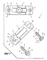
- FIG. 1 An example of an embodiment of a pipe clamp according to the invention is shown in FIG. 1 shown in an exploded representation and in FIG. 2 in a perspective representation and each provided with the reference number 1 as a whole.
- the pipe clamp 1 comprises two approximately semicircular curved brackets 2 and 5 with flanges 3, 4 and 6, 7.
- the brackets 2 and 5 are each on their opposite flanges 3, 6 and 4, 7th fixable to each other.
- fastening bolts 8 are provided, which through passage openings 10, 11 can be plugged into one of the brackets 2 and provided with an internal thread Screw holes 14, 15 can be screwed into the second bracket 5.
- the one with the Screw holes 14, 15 provided second bracket 5 has a threaded shoulder 9 in which Retaining elements can engage around the pipe clamp on the ground, for example a wall or a ceiling.
- the passage opening 11 in the flange 4 of the first bracket 2 is an incision 12 formed, which opens into the flange side wall 17.
- the flange 4 extends the incision 12 in an asymmetrically arranged Undercut 13.
- the undercut 13 has one circular arc shape. It is understood that the undercut 13 is also an may have a shape deviating from the circular arc shape; for example, it could also be elliptical or even polygonal. From manufacturing technology However, the circular arc shape is preferred for reasons.
- the width of the incision 12 is in Dimension the mouth area such that the shaft 18 of the fastening bolt 9 is freely insertable into the incision 12.
- the undercut 13 is arranged asymmetrically and in particular towards the free end of the Flanged 4 offset. In this way, the undercut forms a stop 23 for the fastening bolt 8.
- the undercut 13 opposite Boundary wall 22 of the incision 12 is substantially straight and opens approximately vertically in the flange side wall 17.
- the Incision 12 in its mouth area slightly expanded in a funnel shape be trained.
- the incision 12 side walls with a chamfer (not shown).
- the passage opening 10 on the second flange 3 of the incision 12 Strap 2 is designed as an elongated hole, the width of which is greater than the diameter of the Shaft of the fastening bolt 8 but smaller than the diameter of its head 19th
- the second bracket 5 has a flange 6 opposite the elongated hole Screw hole 14 with an internal thread.
- screw holes 14, 15 has bracket 5 in the region of the screw holes 14, 15 passages 16, the continue to the side facing away from the first bracket 2 and with a Are provided, the length of the screw thread Screw holes 14, 15 enlarged.
- the fastening bolts 8 protrude from the screw holes 14, 15, which are expediently designed as fastening screws.
- the Fastening screws are in their length and in their thread diameter on the respective pipe clamp 1 and its incision 12 or slot 10 and the screw holes 14, 15 matched.
- the diameter of the head 19 is Fastening screws 8 larger than the largest diameter d of the asymmetrical Undercut 13 of the incision 12 or greater than the width of the elongated hole 10.
- the diameter of the shaft 18 of the fastening screws 8 is such that that it can be inserted into the incision 12.
- a fastening bolt 8 has the already mentioned shaft 18, which with is provided with a thread, and a head 19, for example as a lens head is formed and is equipped with a receiving slot for a screwing tool. Below the head 19, the mounting bolt 8 has an axial extension which in illustrated embodiment is designed as a cylindrical collar 20 and a Height h.
- the diameter t of the cylindrical collar 20 is on the Diameter d of the undercut 13 matched and in particular is the same or slightly smaller than the diameter d of the undercut 13.
- Threading the fastening bolt 8 into the undercut 13 is in Transition area from the cylindrical collar 20 to the shaft 18 an inlet chamfer 21 provided, the length of which is up to approximately half the height h of the cylindrical collar is.
- the side of the incision 12 facing the head 19 of the fastening bolt 8 having the first bracket 2 can be a chamfer in the region of the undercut 13 Have recess, the length of which is equal to or less than the height h of the collar 20 on the fastening bolt 8. This facilitates the sliding of the collar 20 into the Undercut 13.
- the brackets are provisional can be fixed to one another without special preparations being made beforehand and, for example, pay attention to an exact setting of the fastening bolts must become.
- the bracket not connected to the surface is on the side swiveling.
- the width of the incision allows the shaft of the Fastening bolt freely from the mouth in the side wall extended range of asymmetric undercut can be introduced.
- the pipe clamp according to the invention can on its inner side receiving the pipe the bracket can be coated with rubber or with soundproofing material or with corresponding slide-on or clip-on insulation elements or the like be provided, for example, around the background of sound vibrations decouple or to allow axial sliding of the pipe in the pipe clamp.
Landscapes
- Engineering & Computer Science (AREA)
- General Engineering & Computer Science (AREA)
- Mechanical Engineering (AREA)
- Clamps And Clips (AREA)
- Supports For Pipes And Cables (AREA)
- Mutual Connection Of Rods And Tubes (AREA)
- Surgical Instruments (AREA)
- Ladders (AREA)
Description
Claims (10)
- Rohrschelle umfassend zwei etwa halbkreisförmig ausgebildete Bügel(2, 5), die mit an ihren Längsenden ausgebildeten Flanschen (4, 7; 3, 6) zusammenfügbar und um eine senkrecht zu zwei zusammengefügten Flanschen (3, 6) verlaufende Achse (A) gegeneinander verschwenkbar sind und an dem der Achse (A) gegenüberliegenden Flanschpaar (4, 7) eine Durchtrittsöffnung (11) und ein korrespondierendes Schraubloch (15) für einen Befestigungsbolzen (8) aufweisen, wobei die Bügel (2, 5) im wesentlichen senkrecht zur Achse (A) gegeneinander längsverschiebbar sind und die Durchtrittsöffnung (11) als in der Seitenwandung (17) eines der Flansche (4) mündender Einschnitt (12) ausgebildet ist, der eine Weite besitzt, welche ein ungehindertes seitliches Einführen des vom zugeordneten Schraubloch (15) am anderen Bügel (5) abragenden Befestigungsbolzens (8) erlaubt, dadurch gekennzeichnet, daß der Einschnitt (12) eine schlüssellochförmige Gestalt mit einer asymmetrisch angeordneten Hinterschneidung (13) aufweist, welche in Gebrauchsstellung als Anschlag (23) für den Schaft (18) des Befestigungsbolzens (8) ausgebildet ist.
- Rohrschelle nach Anspruch 1, dadurch gekennzeichnet, dass die die Schwenkachse (A) aufweisenden Flansche (3, 6) eine Durchgangsbohrung (10) und ein korrespondierendes Schraubloch (14) für eine Befestigungsschraube (8) auweisen, wobei die Durchgangsbohrung (10) als Langloch ausgebildet ist, dessen Breite grösser ist als der Durchmesser des Schaftes (18) der Befestigungsschraube und kleiner als deren Kopfdurchmesser.
- Rohrschelle nach Anspruch 1 oder 2, dadurch gekennzeichnet, dass die asymmetrische Hinterschneidung (13) sich in Richtung des freien Endes des Flansches (4) erstreckt.
- Rohrschelle nach einem der vorangehenden Ansprüche, dadurch gekennzeichnet, dass die der Hinterschneidung (13) gegenüberliegende Begrenzungswandung (22) des Einschnittes (12) im wesentlichen senkrecht in die Seitenwandung (17) des Flansches (4) mündet.
- Rohrschelle nach einem der vorangehenden Ansprüche, dadurch gekennzeichnet, dass der Befestigungsbolzen (8) unterhalb seines Kopfes (19) einen zylindrischen Ringbund (20) aufweist, dessen Durchmesser (t) grösser ist als der Durchmesser des Schaftes (18) des Befestigungsbolzens (8) und gleich gross bzw. geringfügig kleiner ist als der Durchmesser (d) des Einschnittes im Bereich der Hinterschneidung (13), wobei der Ringbund (20) in Gebrauchstellung formschlüssig in der Hinterschneidung (13) gehalten ist.
- Rohrschelle nach Anspruch 5, dadurch gekennzeichnet, dass am Übergang vom Schaft (18) des Befestigungsbolzen (8) zum zylindrischen Ringbund (20) eine Einlauffase (21) angebracht ist, deren Länge bis etwa die Hälfte der Höhe (h) des zylindrischen Ringbundes (20) beträgt.
- Rohrschelle nach Anspruch 6, dadurch gekennzeichnet, dass die dem Kopf (19) des Befestigungsbolzens (8) zugewandte Seite des den Einschnitt (12) aufweisenden Bügels (2) im Bereich der Hinterschneidung (13) eine fasenartige Vertiefung aufweist, deren Länge gleich oder kleiner ist als die Höhe (h) des Ringbundes (20) am Befestigungsbolzen (8).
- Rohrschelle nach einem der Ansprüche 1 - 4, dadurch gekennzeichnet, dass der Befestigungsbolzen (8) eine Senkkopfschraube ist, deren Übergangsbereich vom Durchmesser des Kopfes (19) zum Durchmesser des Schaftes (18) formschlüssig in der Hinterschneidung gehalten ist, wobei die dem Kopf (19) der Senkkopfschraube zugewandte Seite des den Einschnitt (12) aufweisenden Bügels (2) im Bereich der Hinterschneidung (13) eine dem Verlauf des Übergangs (20) am Befestigungsbolzen (8) entsprechende Ansenkung aufweist.
- Rohrschelle nach einem der vorangehenden Ansprüche, dadurch gekennzeichnet, dass der die Schraublöcher (14, 15) aufweisende Bügel (5) im Bereich der Schraublöcher (14, 15) Durchzüge (16) aufweist, die sich zu der dem anderen Bügel (2) abgewandten Seite fortsetzen und mit einem Innengewinde versehen sind.
- Rohrschelle nach einem der vorangehenden Ansprüche, dadurch gekennzeichnet, dass der Einschnitt (12) im Mündungsbereich trichterförmig erweitert ausgebildet ist.
Applications Claiming Priority (4)
| Application Number | Priority Date | Filing Date | Title |
|---|---|---|---|
| DE19531487 | 1995-08-25 | ||
| DE1995131487 DE19531487A1 (de) | 1995-08-25 | 1995-08-25 | Rohrschelle |
| DE19548737 | 1995-12-23 | ||
| DE1995148737 DE19548737A1 (de) | 1995-12-23 | 1995-12-23 | Rohrschelle |
Publications (2)
| Publication Number | Publication Date |
|---|---|
| EP0760445A1 EP0760445A1 (de) | 1997-03-05 |
| EP0760445B1 true EP0760445B1 (de) | 1998-09-16 |
Family
ID=26018041
Family Applications (1)
| Application Number | Title | Priority Date | Filing Date |
|---|---|---|---|
| EP96810386A Expired - Lifetime EP0760445B1 (de) | 1995-08-25 | 1996-06-12 | Rohrschelle |
Country Status (4)
| Country | Link |
|---|---|
| EP (1) | EP0760445B1 (de) |
| AT (1) | ATE171256T1 (de) |
| DE (1) | DE59600564D1 (de) |
| ES (1) | ES2120802T3 (de) |
Cited By (1)
| Publication number | Priority date | Publication date | Assignee | Title |
|---|---|---|---|---|
| USD950369S1 (en) | 2017-05-22 | 2022-05-03 | Erico International Corporation | Pipe clamp |
Families Citing this family (14)
| Publication number | Priority date | Publication date | Assignee | Title |
|---|---|---|---|---|
| FR2792907B1 (fr) * | 1999-04-28 | 2001-07-06 | Plombelec | Procede de rangement de colliers de fixation |
| DE10233338B4 (de) * | 2002-07-23 | 2005-09-22 | Helmut Schulte | Rohrschelle |
| ES1058157Y (es) * | 2004-08-04 | 2005-02-16 | Pujol Ramon Ceravalls | Dispositivo para la fijacion de tubos y similares. |
| EP1741965A1 (de) * | 2005-07-07 | 2007-01-10 | Zurecon Ag | Rohrschelle |
| DE102005058390A1 (de) * | 2005-12-07 | 2007-06-14 | Fischerwerke Artur Fischer Gmbh & Co. Kg | Rohrschelle |
| US8100368B2 (en) | 2005-12-09 | 2012-01-24 | Erico International Corporation | Clamp and seismic sway brace |
| US20070131823A1 (en) | 2005-12-09 | 2007-06-14 | Mominee Daniel S | Clamp for circular objects |
| DE102007000034A1 (de) * | 2007-01-25 | 2008-09-04 | Hilti Ag | Rohrschelle |
| JP2010529392A (ja) * | 2007-06-11 | 2010-08-26 | エリコ インターナショナル コーポレイション | クランプおよび耐震遥動補強 |
| NL2005042C2 (en) * | 2010-07-06 | 2012-01-10 | Walraven Holding Bv J Van | Pipe clip. |
| DE102012106256B4 (de) | 2012-07-11 | 2014-11-13 | Edgar Emil Sinn | Rohrschelle |
| CN113983238A (zh) * | 2021-10-29 | 2022-01-28 | 沪东中华造船(集团)有限公司 | 一种船舶上波纹管安装调整装置及其使用方法 |
| NL2033881B1 (en) * | 2022-12-30 | 2024-07-12 | Walraven Holding Bv J Van | Pipe clip with width curvature at flanges |
| DE202024100391U1 (de) | 2024-01-25 | 2024-01-31 | Edgar Emil Sinn | Rohrschelle |
Family Cites Families (3)
| Publication number | Priority date | Publication date | Assignee | Title |
|---|---|---|---|---|
| FR2533659A1 (fr) * | 1982-09-24 | 1984-03-30 | Ninin Plismy Anciens Ets | Collier de fixation de tuyauteries |
| NL8301406A (nl) * | 1983-04-21 | 1984-11-16 | Walraven J Van Bv | Inrichting voor het bevestigen van een buis op een ondersteuning. |
| DE4409765C2 (de) * | 1994-03-22 | 2002-07-18 | Wemefa Horst Christopeit Gmbh | Rohrbefestigungsvorrichtung |
-
1996
- 1996-06-12 EP EP96810386A patent/EP0760445B1/de not_active Expired - Lifetime
- 1996-06-12 AT AT96810386T patent/ATE171256T1/de active
- 1996-06-12 ES ES96810386T patent/ES2120802T3/es not_active Expired - Lifetime
- 1996-06-12 DE DE59600564T patent/DE59600564D1/de not_active Expired - Lifetime
Cited By (1)
| Publication number | Priority date | Publication date | Assignee | Title |
|---|---|---|---|---|
| USD950369S1 (en) | 2017-05-22 | 2022-05-03 | Erico International Corporation | Pipe clamp |
Also Published As
| Publication number | Publication date |
|---|---|
| ATE171256T1 (de) | 1998-10-15 |
| ES2120802T3 (es) | 1998-11-01 |
| EP0760445A1 (de) | 1997-03-05 |
| DE59600564D1 (de) | 1998-10-22 |
Similar Documents
| Publication | Publication Date | Title |
|---|---|---|
| EP0297033B1 (de) | Verbindungselement für eine Stange | |
| EP0760445A1 (de) | Rohrschelle | |
| EP0796411B1 (de) | Einbauleuchte | |
| EP1156256B1 (de) | Spannring | |
| DE4411220A1 (de) | Rohrmanschette | |
| EP2497989A1 (de) | Rohrklemmanordnung | |
| DD139779A5 (de) | Kabeldurchfuehrung mit zugentlastung | |
| DE9406076U1 (de) | Befestigungsvorrichtung für stabförmige Gegenstände | |
| EP2487399B1 (de) | Steckverbindung für Fluid-Leitungen | |
| EP0504097A1 (de) | Höhenverstellbare Rohrabhängung | |
| DE19946042B4 (de) | Rohrschelle | |
| DE102017110760A1 (de) | Befestigungsset zum Befestigen eines Montagegestells für Sanitärobjekt und Verwendung eines solchen Befestigungssets | |
| DE102016215165B4 (de) | Flugwarnkugel, Montageset für eine solche sowie Verfahren zur Montage einer solchen an einem Seil | |
| DE19548737A1 (de) | Rohrschelle | |
| DE20114345U1 (de) | Vorrichtung zum Halten von Versorgungsleitungen an einem mehrachsigen Industrieroboter | |
| EP0703394B1 (de) | Rohrschelle | |
| EP1195548B1 (de) | Rohrschelle | |
| DE3436710A1 (de) | Rohrschelle | |
| DE19900154A1 (de) | Klammer | |
| DE4002450A1 (de) | Rohrschelle | |
| DE19645894A1 (de) | Rohrschelle | |
| DE29503957U1 (de) | Klemmschelle | |
| DE19531487A1 (de) | Rohrschelle | |
| DE29718042U1 (de) | Rohrschelle | |
| DE60214460T2 (de) | Rohrbefestigungsschelle |
Legal Events
| Date | Code | Title | Description |
|---|---|---|---|
| PUAI | Public reference made under article 153(3) epc to a published international application that has entered the european phase |
Free format text: ORIGINAL CODE: 0009012 |
|
| AK | Designated contracting states |
Kind code of ref document: A1 Designated state(s): AT BE CH DE ES FR GB IT LI NL |
|
| 17P | Request for examination filed |
Effective date: 19970319 |
|
| GRAG | Despatch of communication of intention to grant |
Free format text: ORIGINAL CODE: EPIDOS AGRA |
|
| GRAG | Despatch of communication of intention to grant |
Free format text: ORIGINAL CODE: EPIDOS AGRA |
|
| GRAH | Despatch of communication of intention to grant a patent |
Free format text: ORIGINAL CODE: EPIDOS IGRA |
|
| 17Q | First examination report despatched |
Effective date: 19980302 |
|
| GRAH | Despatch of communication of intention to grant a patent |
Free format text: ORIGINAL CODE: EPIDOS IGRA |
|
| GRAA | (expected) grant |
Free format text: ORIGINAL CODE: 0009210 |
|
| ITF | It: translation for a ep patent filed | ||
| AK | Designated contracting states |
Kind code of ref document: B1 Designated state(s): AT BE CH DE ES FR GB IT LI NL |
|
| REF | Corresponds to: |
Ref document number: 171256 Country of ref document: AT Date of ref document: 19981015 Kind code of ref document: T |
|
| REG | Reference to a national code |
Ref country code: CH Ref legal event code: EP |
|
| REF | Corresponds to: |
Ref document number: 59600564 Country of ref document: DE Date of ref document: 19981022 |
|
| REG | Reference to a national code |
Ref country code: ES Ref legal event code: FG2A Ref document number: 2120802 Country of ref document: ES Kind code of ref document: T3 |
|
| GBT | Gb: translation of ep patent filed (gb section 77(6)(a)/1977) |
Effective date: 19981113 |
|
| ET | Fr: translation filed | ||
| PLBE | No opposition filed within time limit |
Free format text: ORIGINAL CODE: 0009261 |
|
| STAA | Information on the status of an ep patent application or granted ep patent |
Free format text: STATUS: NO OPPOSITION FILED WITHIN TIME LIMIT |
|
| 26N | No opposition filed | ||
| REG | Reference to a national code |
Ref country code: GB Ref legal event code: IF02 |
|
| REG | Reference to a national code |
Ref country code: FR Ref legal event code: PLFP Year of fee payment: 20 |
|
| PGFP | Annual fee paid to national office [announced via postgrant information from national office to epo] |
Ref country code: CH Payment date: 20150612 Year of fee payment: 20 Ref country code: ES Payment date: 20150512 Year of fee payment: 20 Ref country code: GB Payment date: 20150610 Year of fee payment: 20 Ref country code: DE Payment date: 20150609 Year of fee payment: 20 |
|
| PGFP | Annual fee paid to national office [announced via postgrant information from national office to epo] |
Ref country code: FR Payment date: 20150608 Year of fee payment: 20 Ref country code: NL Payment date: 20150609 Year of fee payment: 20 Ref country code: AT Payment date: 20150527 Year of fee payment: 20 Ref country code: BE Payment date: 20150612 Year of fee payment: 20 |
|
| PGFP | Annual fee paid to national office [announced via postgrant information from national office to epo] |
Ref country code: IT Payment date: 20150625 Year of fee payment: 20 |
|
| REG | Reference to a national code |
Ref country code: DE Ref legal event code: R071 Ref document number: 59600564 Country of ref document: DE |
|
| REG | Reference to a national code |
Ref country code: CH Ref legal event code: PL Ref country code: NL Ref legal event code: MK Effective date: 20160611 |
|
| REG | Reference to a national code |
Ref country code: GB Ref legal event code: PE20 Expiry date: 20160611 |
|
| REG | Reference to a national code |
Ref country code: AT Ref legal event code: MK07 Ref document number: 171256 Country of ref document: AT Kind code of ref document: T Effective date: 20160612 |
|
| PG25 | Lapsed in a contracting state [announced via postgrant information from national office to epo] |
Ref country code: GB Free format text: LAPSE BECAUSE OF EXPIRATION OF PROTECTION Effective date: 20160611 |
|
| REG | Reference to a national code |
Ref country code: ES Ref legal event code: FD2A Effective date: 20160926 |
|
| PG25 | Lapsed in a contracting state [announced via postgrant information from national office to epo] |
Ref country code: ES Free format text: LAPSE BECAUSE OF EXPIRATION OF PROTECTION Effective date: 20160613 |