EP0759151B2 - Korrekturverfahren und navigationssystem für die koppelortung eines kraftfahrzeugs - Google Patents
Korrekturverfahren und navigationssystem für die koppelortung eines kraftfahrzeugs Download PDFInfo
- Publication number
- EP0759151B2 EP0759151B2 EP95915800A EP95915800A EP0759151B2 EP 0759151 B2 EP0759151 B2 EP 0759151B2 EP 95915800 A EP95915800 A EP 95915800A EP 95915800 A EP95915800 A EP 95915800A EP 0759151 B2 EP0759151 B2 EP 0759151B2
- Authority
- EP
- European Patent Office
- Prior art keywords
- path
- vehicle
- parallel
- main path
- correction method
- Prior art date
- Legal status (The legal status is an assumption and is not a legal conclusion. Google has not performed a legal analysis and makes no representation as to the accuracy of the status listed.)
- Expired - Lifetime
Links
Images

Classifications
-
- G—PHYSICS
- G01—MEASURING; TESTING
- G01C—MEASURING DISTANCES, LEVELS OR BEARINGS; SURVEYING; NAVIGATION; GYROSCOPIC INSTRUMENTS; PHOTOGRAMMETRY OR VIDEOGRAMMETRY
- G01C21/00—Navigation; Navigational instruments not provided for in groups G01C1/00 - G01C19/00
- G01C21/26—Navigation; Navigational instruments not provided for in groups G01C1/00 - G01C19/00 specially adapted for navigation in a road network
- G01C21/28—Navigation; Navigational instruments not provided for in groups G01C1/00 - G01C19/00 specially adapted for navigation in a road network with correlation of data from several navigational instruments
- G01C21/30—Map- or contour-matching
Definitions
- the invention is based on a correction method for the coupling location according to the preamble of claim 1.
- a map-based navigation system is already known to perform the position determination by a coupling location such that the data supplied by the sensors of a motor vehicle data are compared with those of a digitized road map.
- the determined by the coupling location vehicle position is corrected, wherein the vehicle is placed on a nearby running road. If, however, several roads run at a similar angle compared to the direction of travel of the vehicle, then it may happen that the vehicle is placed on the wrong road. In the course of the further journey, however, the vehicle remains on this "wrong road", since a further check for correctness of this position correction is not carried out.
- an error range is determined for the estimated vehicle position, whose size is predetermined by the tolerances of the sensors for the distance and the direction of travel.
- the vehicle positions calculated for a given driving situation are calculated for all roads within the error range.
- the vehicle position is determined as the actual position whose road course is closest.
- the inventive correction method according to claim 1 has the advantage that a plurality of possible vehicle positions are calculated simultaneously (in parallel), all routes within a driving area are taken into account. Even if a main path for the most likely vehicle position has been found, it remains only until a parallel path, due to plausibility considerations, reaches the greater likelihood of vehicle position. This results in the advantage that the navigation is reliable and the vehicle is always located on the road on which it is actually located.
- the measures listed in the dependent claims advantageous refinements and improvements of the correction method according to claim 1 are possible. It is particularly advantageous that the error range is always dimensioned by the inclusion of the measurement tolerances of the sensors and / or the navigation device so that the vehicle is certainly within the error ranges. This ensures that the possible locations for the vehicle are detected for all roads in the driving area.
- this main path is also selected, for example, taking into account the lifetime of the path or the angle of inclination, then the probability is high that it corresponds to the actual travel path of the vehicle.
- a valuation hysteresis is provided so that a change of the main path takes place only if, by several measurements this has proven to be plausible.
- a further advantage is that when using the invention in a destination management system, the route search is performed so that the main path is used as a starting point for the route calculation. Also, with path ambiguities (two or more paths with nearly equal plausibility), the destination route may become the decision criterion for the main path selection because of the likelihood that the vehicle driver will follow the system recommended route. By means of a parallel path evaluator and comparator, the desired main path can then be corrected at any time from the calculated parallel paths. If the navigation system has an indicator for a road map, then the current main path can be on a Display should be marked accordingly.
- FIG. 1 shows a first block diagram
- FIG. 2 shows a second block diagram
- FIG. 3 shows a function diagram
- FIG. 4 shows a part of a digitized road map
- FIG. 5 shows a further part of a digitized road map
- FIG. 6 shows a third part of a road map.
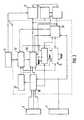
- Figure 1 shows a first block diagram of a map-based navigation system, in which a computing unit 1 is connected on the input side with vehicle sensors 3 for detecting the direction of travel and route. Furthermore, a satellite navigation receiver (for example GPS receiver) 4 is connected, with which a position determination of the vehicle is also possible. Furthermore, the arithmetic unit 1 is connected to an output unit 5, for example a display or an acoustic output. Furthermore, an input unit 6 and a destination guidance unit 7 are connected to the arithmetic unit 1. The route guidance unit 7 or the satellite receiver 4 are optionally provided.
- a computing unit 1 is connected on the input side with vehicle sensors 3 for detecting the direction of travel and route. Furthermore, a satellite navigation receiver (for example GPS receiver) 4 is connected, with which a position determination of the vehicle is also possible. Furthermore, the arithmetic unit 1 is connected to an output unit 5, for example a display or an acoustic output. Furthermore, an input unit 6 and a destination guidance unit 7 are connected to the arithmetic
- FIG. 2 shows in detail a second block diagram of the navigation system, in which the arithmetic unit 1 is shown with a plurality of function blocks.
- the arithmetic unit 1 contains a coupling location 19, in which the signals of the sensors 3 and / or the satellite receiver 4 are input.
- the coupling location 19 calculates a new position for the vehicle from the sensor signals and the previous position.
- the coupling location result and the sensor evaluation are given to an error estimator 21, which determines an error range 25 due to known tolerance errors (FIG. 4).
- the error range 25 is given to a selector 22, which is connected on the one hand to the card memory 2.
- the map memory 2 gives the roads to the selector 22, which fall into the driving area 24. This driving area 24 then corresponds to the main path and parallel path area of the road map (FIG. 4).
- the selector 22 is connected to a control computer 20 and forwards the main path and parallel path area to the control computer 20. Furthermore, the control computer 20 is connected to the coupling location 19 and receives from this the coupling location data for the vehicle.
- the control computer initially determines the main path independently of the parallel paths. Further possible vehicle positions next to the main path (parallel paths) are detected here and followed on the parallel path computers 11, 12. Each parallel path computer can in turn recognize several plausible vehicle positions and then start additional parallel paths on the parallel path computers.
- the parallel path computers are controlled via corresponding START control lines. Each parallel path computer is supplied with the map section of the driving area 24 via the selector 22.
- the parallel path computers 11, 12 are connected to a parallel path evaluator and comparator 23.
- the parallel path evaluator / comparator evaluates the parallel paths based on their status information (e.g., match of direction of travel and direction of the road). The parallel paths that are no longer plausible in the comparison of the parallel paths and the main path plausibility are deleted.
- the information of the absolute vehicle position and the estimated scattering range of a satellite navigation receiving and evaluating device 4 can also cause the deletion of parallel paths whose position is no longer in the scattering range of the satellite navigation position.
- the parallel path comparator 23 is connected to the coupling location 19, to which it can provide correction data for the vehicle position (path correction).
- this When using a route guidance unit 7, this also gives its data to the parallel path comparator 23, so that path ambiguities the path is selected as the main path that forms an element of the route to the destination.
- a correction of the coupling location position can also be done directly from the satellite receiving and evaluation device 4.
- the control computer 20 is connected to an output unit 5, on which, for example, in a graphic illustration, a road section is shown with the main path and a marking of the vehicle. However, it is also possible to provide directional arrows / driving recommendations or an acoustic output via the route guidance unit 7.
- the input unit 6 is connected on the one hand to the arithmetic unit 1, on the other hand to the destination guide unit 7, so that u.a. the destination input can be entered.
- FIG. 3 shows by way of example a function diagram for the position calculation and status determination of a parallel path by the parallel path computer 11, 12.
- the vehicle position X is to be calculated on a parallel path 31 that lies within the travel area 24.
- the parallel path computer 11, 12 extracts from the card memory 2 the card part corresponding to the travel area 24 (position a).
- position b the direction of travel and the travel distance of the motor vehicle, which was determined by the coupling location 19, entered.
- another parallel path computer 11, 12 can be started, if in this position calculation of the vehicle Again path ambiguities arise.
- a status is still determined in which, for example, a current match between the direction of travel and the road angle is determined.
- a probability factor for the vehicle position may be specified.
- the status information also contains information about the lifetime of the parallel path.
- Both the position and the status determination are passed via an output 11 to the parallel path comparator 23, which outputs a main path and current parallel paths from all available information on the basis of plausibility checks. For example, the inclination angle of a route can be compared with that of the vehicle and from this the main path can be determined. If a parallel path no longer falls into the driving area or if it no longer matches the coupling course, then it can be deleted via an input e.
- the function diagram can be designed as a program for the computer 1.
- Figure 4 shows a driving area 24, in which the passable roads 40 to 45 are shown. It is assumed that the vehicle is initially in position X on the road 40, which is currently designated as the main path. Bends now the vehicle from the right, then results due to the positive feedback and due to angular and longitudinal error of the vehicle sensors a position X1. Because of the errors, an error range 25 is formed around the position X1, as it has already been the position X. The error range 25 can be different for each calculated position X ... X4. The size of the error range is determined by the given tolerances. FIG. 4 therefore shows different error ranges 25 for the individual positions X... X4. The large, rectangular error field 25 of the position X moves, for example, with the new vehicle position X1, thereby changing its width.
- the new position X2 is therefore assumed on the road 43 which follows the calculated position X1 next.
- the control computer 20 now determines the possible positions X2, X3 and X4 with the corresponding new error ranges 25 on the parallel paths 42, 43 and 44 due to the turning angle of the vehicle compared to all roads that have formed a similar angle to the previous main path 40.
- the roads 42, 43, 44 are located in the error area of the path position X1.
- the road 41 forms a turning angle in the opposite direction and is therefore no longer suitable for determining the position.
- the described method in which parallel path positions (here X2, X3 and X4 on the streets 44, 43 and 42) emerge from the error area 25 of the main path, can likewise be applied by generating parallel paths from the error area 25 of a parallel path.
- the error area 25 includes the heading sense error and a one-dimensional location area (possible length error) or a two-dimensional location area (lateral and longitudinal error of the assumed position). Due to plausibility considerations, the position X2 with the new error field 25 is selected from the positions X1 to X4 as the new main path for which the greatest probability of the vehicle position exists.
- the positions X3, X4 on the parallel paths 42, 44 are further calculated and taken into account in the next selection.
- the turn-off point on the intersection 43, 40 can be used as a defined correlation point for the length measurement.
- the difference X1 - X2 can be used for length correction. Accordingly, the method for determining the parallel path positions x3 and x4 is to be performed.
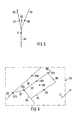
- a position correction according to FIG. 5 can be carried out.
- the vehicle is on the main path 50 in the position X. It is now assumed that the main path 50 splits at a fork in two parallel paths 51, 52. Due to the coupling location, the vehicle would be at a certain time in position X5. Since position X5 is not a location on a road, possible locations X6 on parallel path 51 or X7 on parallel path 52 are acceptable. If the position is determined repeatedly, for example, the probability of the position X7 on the parallel path 52 is also due to the recommended route to the destination, which is now pursued as the main path.
- the parallel path 51 is furthermore relevant and is further calculated with the parallel path computer 11, 12. Due to the change in angle from position X5 to X7, a correction value for the direction determination results, which can be used as the basis for the further coupling location.
- FIG. 6 shows a third part of a road map of a navigation system in which a satellite navigation receiver 4 (eg GPS) is used for the coupling location correction.
- the satellite navigation receiver determines its position from the location of several navigation satellites. This position determination is also associated with a certain error. This error will be similar to the examples of Figures 4 or 5 compensated.
- road sections / parallel paths 61 to 68 are shown. If, for example, the GPS receiver 4 determines the position X8 as a possible location for the vehicle, then the position X9 on the parallel path 61 and X10 on the parallel path 63 are additionally calculated in the direction of travel D.
- positions X13 on 66, X14 on 67 and X12 on 68 can be calculated.
- a position of the motor vehicle on the parallel paths 64 or 65 is unlikely for reasons of plausibility and therefore decides.
- recalculation gives the greatest probability, for example for a position X11 on the parallel path 62, which now becomes the main path.
- the motor vehicle is now assumed at position X11 and this position is output, for example, on a display 5.
- the positions X9, X10, X12, X13, X14 on the original roads 61, 63, 68, 66, 67 are tracked to control the main path 62. However, they are not displayed on the display 5.
- the navigation system is coupled to a route guidance device 7, then after entering a destination via the input 6, a specific destination route is selected by the arithmetic unit 1.
- the target route is now set to be calculated with the new main path 62 as the starting position.
- the individual assemblies of the navigation system or the computing unit 1 such as the coupling location 19, the error estimator 21, the selector 22, the parallel path computers 11, 12 or the parallel path comparator 23 are constructed with known devices, such as amplifiers, comparators or logic devices. These are familiar to those skilled in the known navigation systems and therefore need not be explained in more detail. Instead of individual components, one or more microcomputers can also be provided, which are controlled by a corresponding control program.
Landscapes
- Engineering & Computer Science (AREA)
- Radar, Positioning & Navigation (AREA)
- Remote Sensing (AREA)
- Automation & Control Theory (AREA)
- Physics & Mathematics (AREA)
- General Physics & Mathematics (AREA)
- Navigation (AREA)
- Traffic Control Systems (AREA)
- Position Fixing By Use Of Radio Waves (AREA)
- Instructional Devices (AREA)
Description
- Die Erfindung geht aus von einem Korrekturverfahren für die Koppelortung nach der Gattung des Anspruchs 1. Bei einem kartengestützten Navigationssystem ist schon bekannt, die Positionsbestimmung durch eine Koppelortung derart durchzuführen, daß die von den Sensoren eines Kraftfahrzeugs gelieferten Daten mit denen einer digitalisierten Straßenkarte verglichen werden. Die von der Koppelortung ermittelte Fahrzeugposition wird korrigiert, wobei das Fahrzeug auf eine in der Nähe verlaufende Straße aufgesetzt wird. Verlaufen jedoch mehrere Straßen im Vergleich zur Fahrtrichtung des Fahrzeuges in einem ähnlichen Winkel, dann kann es vorkommen, daß das Fahrzeug auf die falsche Straße aufgesetzt wird. Im Verlauf der weiteren Fahrt bleibt jedoch das Fahrzeug auf dieser "falschen Straße", da eine weitere Überprüfung auf Richtigkeit dieser Positionskorrektur nicht durchgeführt wird.
- Bei dem Navigationssystem der EP 0314 806 A1 wird für die geschätzte Fahrzeugposition ein Fehlerbereich bestimmt, dessen Größe von den Toleranzen der Sensoren für die Wegstrecke und die Fahrtrichtung vorbestimmt ist. Mittels eines Rechners werden für alle Straßen innerhalb des Fehlerbereich die Fahrzeugpositionen berechnet, die für eine gegebene Fahrsituation gegeben sind. Durch Schätzung der Abstände und anderer Parameter wird die Fahrzeugposition als Istposition bestimmt, deren Straßenverlauf am nächsten liegt. Bei diesem Koppelverfahren ergibt sich das Problem, daß bei einem engen Straßennetz mit mehreren dicht beieinanderliegenden Prallelpfaden nicht Immer die Straße gefunden werden kann, auf der das Fahrzeug tatsächlich fährt.
- Das erfindungsgemäße Korrekturverfahren nach dem Anspruch 1 hat demgegenüber den Vorteil, daß mehrere mögliche Fahrzeugpositionen gleichzeitig (parallel) berechnet werden, wobei alle Fahrwege innerhalb eines Fahrgebietes berücksichtigt werden. Selbst wenn ein Hauptpfad für die wahrscheinlichste Fahrzeug-Position gefunden wurde, bleibt dieser nur solange erhalten, bis ein Parallelpfad aufgrund von Plausibilitätsbetrachtungen die größere Wahrscheinlichkeit für die Fahrzeugposition erreicht. Dadurch ergibt sich der Vorteil, daß die Navigation zuverlässiger wird und das Fahrzeug stets auch auf der Straße lokalisiert wird, auf der es sich tatsächlich befindet.
- Durch die in den abhängigen Ansprüchen aufgeführten Maßnahmen sind vorteilhafte Weiterbildungen und Verbesserungen des Korrekturverfahrens nach Anspruch 1 möglich. Besonders vorteilhaft ist, daß durch die Einbeziehung der Meßtoleranzen der Sensoren und/oder des Navigationsgerätes der Fehlerbereich stets so bemessen wird, daß sich das Fahrzeug mit Sicherheit innerhalb der Fehlerbereiche befindet. Dadurch wird gewährleistet, daß für alle Straßen im Fahrgebiet die möglichen Standorte für das Fahrzeug erfaßt werden.
- Günstig ist weiterhin, die Straße als Hauptpfad auszuwählen, dessen Richtung in etwa mit der des gekoppelten Fahrweges übereinstimmt und die diesem am nächsten liegt. Wird im Verlauf weiterer Messungen dieser Hauptpfad beispielsweise auch unter Berücksichtigung der Lebensdauer des Pfades oder des Neigungswinkels derneut ausgewählt, dann ist die Wahrscheinlichkeit groß, daß dieser dem tatsächlichen Fahrweg des Fahrzeugs entspricht.
- Um beispielsweise bei parallel laufenden Straßen, die streckenweise in einem engen Abstand verlaufen, ein Hin- und Herwechseln der wahrscheinlichsten Fahrzeugposition (Hauptpfad-Position) zu vermeiden, wird eine Bewertungshysterese vorgesehen, so daß eine Änderung des Hauptpfades erst dann erfolgt, wenn durch mehrere Messungen sich diese als plausibel erwiesen hat.
- Bei der Längenmessung des Fahrweges treten sensorbedingte Fehler auf, die auf einfache Weise dann erkannt werden können, wenn das Fahrzeug eine Auslenkung oder eine Abbiegung an einer Kreuzung durchführt. Da die Position der Kreuzung durch ihre exakten Koordinaten festgelegt ist, ergibt sich somit ein Bezugspunkt zwischen zwei Meßmarken, die für die Korrektur der Längenmessung verwendbar ist.
- Da die Positionsbestimmung des Fahrzeuges auch mit Navigationssatelliten erfolgen kann, können quer zur Fahrtrichtung auftretende Fehler am einfachsten dadurch beseitigt werden, daß das Fahrzeug quer zur Fahrtrichtung rechnerisch auf allen ungefähr parallel verlaufenden Straßen aufgesetzt wird. Diese Parallelpfade werden bei der weiteren Fahrt weiterverfolgt und dabei so überprüft, daß nach einer Plausibilitätsprüfung der wahrscheinlichste Parallelpfad als neuer Hauptpfad bestimmt wird.
- Vorteilhaft ist weiter, daß bei Verwendung der Erfindung in einem Ziel führungssystem die Routensuche so durchgeführt wird, daß der Hauptpfad als Ausgangspunkt für die Routenberechnung verwendet wird. Auch kann bei Pfad-Mehrdeutigkeiten (zwei oder mehrere Pfade mit nahezu gleicher Plausibilität) die Zielroute das Entscheidungskriterium zur des Hauptpfadauswahl werden, da die Wahrscheinlichkeit groß ist, daß der Fahrzeugführer der vom System empfohlenen Route folgt. Mittels eines Parallelpfad-Bewerters und Vergleichers kann dann aus den errechneten Parallelpfaden der gewünschte Hauptpfad jederzeit korrigiert werden. Hat das Navigationssystem eine Anzeige für eine Straßenkarte, dann kann der aktuelle Hauptpfad auf einer Anzeige entsprechend markiert werden.
- Ein Ausführungsbeispiel der Erfindung ist in der Zeichnung dargestellt und in der nachfolgenden Beschreibung näher erläutert. Es zeigen Figur 1 ein erstes Blockschaltbild, Figur 2 zeigt ein zweites Blockschaltbild, Figur 3 zeigt einen Funktionsplan, Figur 4 zeigt einen Teil einer digitalisierten Straßenkarte, Figur 5 zeigt einen weiteren Teil einer digitalisierten Straßenkarte und Figur 6 zeigt einen dritten Teil einer Straßenkarte.
- Figur 1 zeigt ein erstes Blockschaltbild eines kartengestützten Navigationssystems, bei dem eine Recheneinheit 1 eingangsseitig mit Fahrzeugsensoren 3 zur Erfassung der Fahrtrichtung und Fahrtstrecke verbunden ist. Desweiteren ist ein Satellitennavigationsempfänger (z.B. GPS-Empfänger) 4 angeschlossen, mit dem ebenfalls eine Positionsbestimmung des Fahrzeugs möglich ist. Desweiteren ist die Recheneinheit 1 mit einer Ausgabeeinheit 5, beispielsweise einem Display oder einer akustischen Ausgabe verbunden. Ferner ist eine Eingabeeinheit 6 und eine Zielführungseinheit 7 mit der Recheneinheit 1 verbunden. Die Zielführungseinheit 7 oder der Satelliten-Empfänger 4 sind wahlweise vorgesehen.
- Figur 2 zeigt in detaillierter Ausführung ein zweites Blockschaltbild des Navigationssystems, bei dem die Recheneinheit 1 mit mehreren Funktionsblökken dargestellt ist. Die Recheneinheit 1 enthält eine Koppelortung 19, in die die Signale der Sensoren 3 und/oder des Satellitenempfängers 4 eingegeben werden. Die Koppelortung 19 berechnet aus den Sensorsignalen und der vorherigen Position eine neue Position für das Fahrzeug. Das Koppelortungsergebnis und die Sensorauswertung werden auf einen Fehlerschätzer 21 gegeben, der aufgrund von bekannten Toleranzfehlern einen Fehlerbereich 25 festlegt (Figur 4). Der Fehlerbereich 25 wird in einen Selektor 22 gegeben, der einerseits mit dem Kartenspeicher 2 verbunden ist. Der Kartenspeicher 2 gibt die Straßen an den Selektor 22, die in das Fahrgebiet 24 fallen. Dieses Fahrgebiet 24 entspricht dann dem hauptpfad und Parallelpfad-Gebiet der Straßenkarte (Figur 4).
- Der Selektor 22 ist mit einem Steuerrechner 20 verbunden und gibt das Hauptpfad- und Parallelpfad-Gebiet an den Steuerrechner 20 weiter. Desweiteren ist der Steuerrechner 20 mit der Koppelortung 19 verbunden und erhält von dieser die Koppelortungsdaten für das Fahrzeug. Der Steuerrechner bestimmt zunächst unabhängig von den Parallelpfaden den Hauptpfad. Weitere mögliche Fahrzeugpositionen neben dem Hauptpfad (Parallelpfade) werden hier festgestellt und auf den Parallelpfadrechnern 11, 12 weiterverfolgt. Jeder Parallelpfadrechner kann wiederum mehrere plausible Fahrzeugpositionen erkennen und daraufhin weitere Parallelpfade auf den Parallelpfadrechnern starten. Die Parallelpfadrechner werden über entsprechende Steuerleitungen START gesteuert. Jeder Parallelpfadrechner wird dabei mit dem Kartenausschnitt des Fahrgebietes 24 über den Selektor 22 versorgt.
- Die Parallelpfadrechner 11, 12 sind mit einem Parallelpfad-Bewerter und Vergleicher 23 verbunden. Der Parallelpfad-Bewerter/Vergleicher bewertet die Parallelpfade aufgrund ihrer Statusinformationen (z.B. Übereinstimmung der Fahrtrichtung und der Straßenrichtung). Die im Vergleich der Parallelpfade und der Hauptpfad-Plausibilität nicht mehr plausiblen Parallelpfade werden gelöscht.
- Auch die Information der absoluten Fahrzeugposition und des geschätzten Streubereichs einer Satellitennavigationsempfangs- und Auswerteeinrichtung 4 kann das Löschen von Parallelpfaden, deren Position sich nicht mehr im Streubereich der Satellitennavigations-Position befinden, bewirken.
- Desweiteren ist der Parallelpfad-Vergleicher 23 mit der Koppelortung 19 verbunden, an die er Korrekturdaten für die Fahrzeugposition liefern kann (Pfadkorrektur).
- Bei Verwendung einer Zielführungseinheit 7 gibt diese ihre Daten ebenfalls an den Parallelpfad-Vergleicher 23, damit bei Pfadmehrdeutigkeiten der Pfad als Hauptpfad ausgewählt wird, der ein Element der Route zum Ziel bildet.
- Eine Korrektur der Koppelortungsposition kann auch direkt von der Satellitenempfangs- und Auswerteeinrichtung 4 erfolgen.
- Der Steuerrechner 20 ist mit einer Ausgabeeinheit 5 verbunden, auf der beispielsweise bei einer graphischen Darstellung ein Straßenausschnitt mit dem Hauptpfad und einer Markierung des Fahrzeugs dargestellt ist. Es können aber auch Richtungspfeile/Fahrempfehlungen oder eine akustische Ausgabe über die Zielführungseinheit 7 vorgesehen sein.
- Die Eingabeeinheit 6 ist einerseits mit der Recheneinheit 1 verbunden, andererseits mit der Zielführungseinheit 7, so daß u.a. die Zieleingabe eingegeben werden kann.
- Im folgenden wird anhand der Figuren 3 bis 6 die Funktionsweise dieser Anordnung näher erläutert.
- Figur 3 zeigt beispielshaft einen Funktionsplan für die Positionsberechnung und Statusbestimmung eines Parallelpfades durch den Parallelpfadrechner 11, 12. Beispielsweise soll die Fahrzeugposition X auf einem Parallelpfad 31 berechnet werden, der innerhalb des Fahrgebiets 24 liegt. Nach dem Startsignal d entnimmt der Parallelpfadrechner 11, 12 dem Kartenspeicher 2 den Kartenteil, der dem Fahrgebiet 24 entspricht (Position a). In Position b wird die Fahrtrichtung und die Fahrtstrecke des Kraftfahrzeugs, die von der Koppelortung 19 ermittelt wurde, eingegeben. Am Ausgang c kann ein weiterer Parallelpfadrechner 11, 12 gestartet werden, falls bei dieser Positionsberechnung des Fahrzeugs erneut Pfadmehrdeutigkeiten entstehen. Zusätzlich zu der Position wird noch ein Status bestimmt, in dem beispielsweise eine aktuelle Übereinstimmung zwischen der Fahrtrichtung und des Straßenwinkels festgelegt ist. Desweiteren kann in der Statusinformation beispielsweise ein Wahrscheinlichkeitsfaktor für die Fahrzeugposition festgelegt sein. Auch enthält die Statusinformation Angaben über die Lebensdauer des Parallelpfades. Sowohl die Positions- als auch die Statusbestimmung wird über einen Ausgang 11 an den Parallelpfad-Vergleicher 23 geleitet, der aus allen vorliegenden Informationen auf der Grundlage von Plausibilitätsprüfungen einen Hauptpfad und aktuelle Parallelpfade ausgibt. Beispielsweise kann auch der Neigungswinkel einer Fahrstraße mit dem des Fahrzeugs verglichen werden und daraus der Hauptpfad bestimmt werden. Fällt ein Parallelpfad nicht mehr in das Fahrgebiet oder stimmt er mit dem Koppelkurs nicht mehr überein, dann kann er über einen Eingang e gelöscht werden. Der Funktionsplan kann als Programm für den Rechner 1 ausgebildet sein.
- Figur 4 zeigt ein Fahrgebiet 24, in dem die befahrbaren Straßen 40 bis 45 dargestellt sind. Es wird angenommen, daß sich das Fahrzeug zunächst in Position X auf der Straße 40 befindet, die im Augenblick als Hauptpfad festgelegt ist. Biegt nun das Fahrzeug rechts ab, dann ergibt sich aufgrund der Mitkopplung und bedingt durch Winkel- und Längenfehler der Fahrzeugsensoren eine Position X1. Wegen der Fehler wird um die Position X1 wie bereits um die Position X, ein Fehlerbereich 25 gebildet. Der Fehlerbereich 25 kann für jede berechnete Position X ... X4 unterschiedlich groß sein. Die Größe des Fehlerbereichs ist durch die vorgegebenen Toleranzen bestimmt. Figur 4 zeigt daher unterschiedliche Fehlerbereiche 25 für die einzelnen Positionen X ... X4. Das große, rechteckige Fehlerfeld 25 der Position X wandert beispielsweise mit der neuen Fahrzeugposition X1 mit und verändert dabei seine Breite. Daraus ergibt sich, daß die tatsächliche Fahrzeugposition in diesem Feld liegt. Die neue Position X2 wird daher auf der Straße 43 angenommen , die der berechneten Positon X1 am nächsten folgt. Der Steuerrechner 20 ermittelt nun aufgrund des Abbiegewinkels des Fahrzeugs im Vergleich zu allen Straßen, die einen ähnlichen Winkel zum bisherigen Hauptpfad 40 gebildet haben, auf den Parallelpfaden 42, 43 und 44 die möglichen Positionen X2, X3 und X4 mit den entsprechenden neuen Fehlerbereichen 25. Die Straßen 42, 43, 44 befinden sich im Fehlerbereich der Pfadposition X1. Die Straße 41 bildet einen Abbiegewinkel in die entgegengesetzte Richtung und kommt daher für die Positionsbestimmung nicht mehr in Frage. Das beschriebene Verfahren, bei dem Parallelpfadpositionen (hier X2, X3 und X4 auf den Straßen 44, 43 und 42) aus dem Fehlerbereich 25 des Hauptpfades hervorgehen, kann gleichermaßen durch die Erzeugung von Parallelpfaden aus dem Fehlerbereich 25 eines Parallelpfades angewendet werden. Der Fehlerbereich 25 umfaßt den Fahrtrichtungsmeßfehler und einen eindimensionalen Aufenthaltsbereich (möglicher Längenfehler) oder einen zweidimensionalen Aufenthaltsbereich (Quer- und Längsfehler der angenommenen Position). Aufgrund von Plausibilitätsüberlegungen wird aus den Positionen X1 bis X4 die Position X2 mit dem neuen Fehlerfeld 25 als neuen Hauptpfad ausgewählt, für die die größte Wahrscheinlichkeit der Fahrzeugposition besteht. Die Positionen X3, X4 auf den Parallelpfaden 42, 44 werden weiter berechnet und bei der nächsten Auswahl wieder berücksichtigt. Sollte bei einer der nächsten Positionsbestimmungen einer der Parallelpfade 42 oder 44 als Hauptpfad in Frage kommen, dann würde einer der beiden Parallelpfade als neuer Hauptpfad bestimmt werden. Um in Grenzfällen ein häufiges Hin- und Herspringen der Fahrzeugposition X2 zu vermeiden, ist zur Bewertung eine zeitliche oder wegstreckenbezogene Hysterese vorgesehen, so daß eine Änderung der Bestimmung eines Parallelpfades als neuer Hauptpfad erst aufgrund einiger Meßzyklen oder einer bestimmten zurückgelegten Wegstrecke erfolgt.
- Der Figur 4 ist weiter entnehmbar, daß bei einer Abbiegung in den neuen Hauptpfad 43 der Abbiegepunkt auf der Kreuzung 43, 40 als definierter Korrelationspunkt für die Längenmessung verwendet werden kann. Alternativ kann die Differenz X1 - X2 zur Längenkorrektur verwendet werden. Entsprechend ist das Verfahren zur Ermittlung der Parallelpfadpositionen x3 und x4 durchzuführen.
- Ähnlich wie die Längenkorrektur gemäß der Figur 4 kann eine Positionskorrektur gemäß der Figur 5 durchgeführt werden. Beispielsweise befindet sich das Fahrzeug auf dem Hauptpfad 50 in der Position X. Es wird nun angenommen, daß sich der Hauptpfad 50 an einer Gabelung in zwei Parallelpfade 51, 52 aufteilt. Aufgrund der Koppelortung würde sich das Fahrzeug zu einem bestimmten Zeitpunkt in der Position X5 befinden. Da die Position X5 kein Standort auf einer Straße ist, sind mögliche Positionen X6 auf dem Parallelpfad 51 oder X7 auf dem Parallelpfad 52 annehmbar. Bei wiederholter Positionsbestimmung ergibt sich beispielsweise auch aufgrund der empfohlenen Route zum Ziel eine Wahrscheinlichkeit für die Position X7 auf dem Parallelpfad 52, der nun als Hauptpfad weiterverfolgt wird. Der Parallelpfad 51 ist weiterhin relevant und wird mit dem Parallelpfadrechner 11, 12 weiterhin berechnet. Aufgrund der Winkeländerung von Position X5 auf X7 ergibt sich ein Korrekturwert für die Richtungsbestimmung, die der weiteren Kuppelortung zugrundegelegt werden kann.
- Figur 6 zeigt einen dritten Teil einer Straßenkarte eines Navigationssystems, bei dem ein Satellitennavigations-Empfänger 4 (z.B. GPS) für die Koppelortungskorrektur verwendet wird. Der Satellitennavigations-Empfänger ermittelt seine Position aus dem Standort von mehreren Navigationssatelliten. Diese Positionsbestimmung ist ebenfalls mit einem gewissen Fehler behaftet. Dieser Fehler wird ähnlich wie bei den Beispielen der Figuren 4 oder 5 kompensiert. In dem Fehlerfeld 24 der Figur 6 sind Straßenabschnitte/Parallelpfade 61 bis 68 dargestellt. Ermittelt beispielsweise der GPS-Empfänger 4 als möglichen Standort für das Fahrzeug die Position X8, dann wird in Fahrtrichtung D gesehen, zusätzlich die Position X9 auf dem Parallelpfad 61 und X10 auf dem Parallelpfad 63 berechnet. Aber auch die Positionen X13 auf 66, X14 auf 67 und X12 auf 68 können berechnet werden. Eine Position des Kraftfahrzeugs auf den Parallelpfaden 64 oder 65 ist aus Plausibilitätsgründen unwahrscheinlich und scheidet daher aus. Im weiteren Verlauf ergibt sich durch Neuberechnung die größte Wahrscheinlichkeit beispielsweise für eine Position X11 auf dem Parallelpfad 62, der nun zum Hauptpfad wird. Das Kraftfahrzeug wird nun an der Position X11 angenommen und diese Position beispielsweise auf einem Display 5 ausgegeben. Die Positionen X9, X10, X12, X13, X14 auf den ursprünglichen Straßen 61, 63, 68, 66, 67 werden zur Kontrolle des Hauptpfades 62 weiterverfolgt. Sie werden aber auf dem Display 5 nicht angezeigt.
- Ist das Navigationssystem beispielsweise mit einem Zielführungsgerät 7 gekoppelt, dann wird nach Eingabe eines Ziels über die Eingabe 6 von der Recheneinheit 1 eine bestimmte Zielroute ausgesucht. Die Zielroute wird nun so gelegt, daß sie mit dem neuen Hauptpfad 62 als Startposition berechnet wird.
- Die einzelnen Baugruppen des Navigationssystems bzw. der Recheneinheit 1 wie die Koppelortung 19, der Fehlerschätzer 21, der Selektor 22, die Paralellpfadrechner 11, 12 oder der Parallelpfad-Vergleicher 23 sind mit bekannten Bausteinen, wie Verstärkern, Komparatoren oder logischen Bausteinen aufgebaut. Diese sind dem Fachmann aus den bekannten Navigationssystemen geläufig und müssen daher nicht näher erläutert werden. Anstelle von einzelnen Bausteinen ist auch ein oder mehrere Mikrorechner vorsehbar, die mit einem entsprechenden Steuerprogramm gesteuert werden.
Claims (9)
- Korrekturverfahren für ein kartengestütztes Navigationssystem, bei dem durch Koppelortung eine fiktive Position eines Kraftfahrzeugs bestimmt und diese als Ist-Position vorzugsweise auf einer Straßenkarte einer Anzeige ausgegeben wird, wobei die Ist-Position derart bestimmt wird, daß das Kraftfahrzeug auf einer in Fahrtrichtung in etwa parallel verlaufenden Straße aufgesetzt wird,- wobei aus den von Fahrzeugsensoren (3) und/ oder von einem Navigationsgerät (4) gelieferten Signalen ein Fahrgebiet (24) für die Ist-Position (X2; X7; X11) des Fahrzeugs gebildet wird, wobei die ermittelte Ist-Position (X2; X7; X11) einen vorgegebenen Fehlerbereich für Längen- ,Quer- und/oder Richtungsfehler (25) umfaßt,- wobei einem Kartenspeicher (2) alle Fahrstraßen entnommen werden, die im gebildeten Fahrgebiet (24) liegen und die somit den möglichen Hauptpfad und die möglichen Parallelpfade für den Fahrweg des Fahrzeugs bilden,- wobei durch Plausibilitätsprüfung die Hauptpfadposition (X2;X7) auf die Straße (43;52) im Fehlerbereich (25) des bisherigen Hauptpfades (40;50) gesetzt wird, die dem durch Koppelortung bestimmten Fahrweg am nächsten liegt,- wobei die anderen Pfade mit ihren möglichen Positionen (X3, X4;X9 bis X14), solange sie plausibel sind, als Parallelpfade weiterverfolgt werden und- wobei bei weiteren Plausibilitätsprüfungen der bisherige Hauptpfad (43; 52; 62) oder einer der Parallelpfade als neuer Hauptpfad bestimmbar ist, wenn der mitgekoppelte Fahrweg mit dem jeweiligen Pfad am besten übereinstimmt,dadurch gekennzeichnet, daß zu jedem Parallelpfad ein jeweiliger Fehlerbereich vorgegeben wird, der durch die jeweiligen, vorgegebenen Toleranzen der Fahrzeugsensoren bestimmt wird, wobei der Fehlerbereich (25) einen ein- oder zweidirnensionalen Bereich für Längen- oder Längen- und Querfehler und/oder einen Fahrtrichtungsbereich umfaßt und daß die Differenz zwischen einer gemessenen und einer Istposition des Fahrzeugs zur Korrektur der Längen- und Winkelmessung für die weitere Koppelortung zugrundegelegt wird.
- Korrekturverfahren nach Anspruch 1, dadurch gekennzeichnet, daß ein Parallelpfad, der aus einem Parallelpfad oder einem Hauptpfad hervorgeht, die Bewertung und den Status dieses Haupt- oder Parallelpfades zunächst beibehält.
- Korrekturverfahren nach nach einem der vorhergehenden Ansprüche, dadurch gekennzeichnet, daß der Parallelpfad als neuer Hauptpfad ausgewählt wird, dessen Richtung in etwa mit der mitgekoppelten Fahrtrichtung und/oder weiteren Parametern übereinstimmt.
- Korrekturverfahren nach einem der vorhergehenden Ansprüche, dadurch gekennzeichnet, daß für die Pfadbewertung die jeweilige Übereinstimmung zwischen dem Neigungswinkel des Fahrzeugs und dem Steigungs-/Gefällwinkel des Straßenabschnitts und/oder die Lebensdauer des Pfades berücksichtigt wird.
- Korrekturverfahren nach einem der vorhergehenden Ansprüche, dadurch gekennzeichnet, daß bei der Bewertung des Hauptpfades (43; 52; 62) und der Parallelpfade ein Hystereseverhalten gebildet wird, durch das ein Wechsel zu einem anderen Parallelpfad verzögert wird.
- Korrekturverfahren nach einem der vorhergehenden Ansprüche, dadurch gekennzeichnet, daß der Längenfehler der Koppelortung dadurch korrigiert wird, daß nach einer Kurvenfahrt die ermittelte Fahrzeugposition (X1) im Vergleich zu einer im Fehlerbereich liegenden Straßenposition (X2) verglichen wird und deren Differenz zur Korrektur des Längenfehlers der Koppelortung verwendet wird.
- Korrekturverfahren nach einem der vorhergehenden Ansprüche, dadurch gekennzeichnet, daß bei einer Neupositionierung des Kraftfahrzeugs die Positionsbestimmung mittels eines Navigations-Satellitenempfängers dadurch erfolgt, daß neben dem Hauptpfad (62) Parallelpfade (61, 63, 66, 67, 68) auf allen plausibel erscheinenden Straßen gebildet werden, die etwa parallel zur Fahrtrichtung D des Fahrzeugs verlaufen (Figur 6).
- Korrekturverfahren nach Anspruch 7, dadurch gekennzeichnet, daß die Parallelpfade verworfen werden, die den Fehlerbereich der Satellitennavigations-Positionsermittlung verlassen haben.
- Korrekturverfahren nach einem der vorhergehenden Ansprüche, dadurch gekennzeichnet, daß bei Verwendung eines Zielführungssystems (7) der aktuelle Hauptpfad (43; 52; 62) bei Pfadmehrdeutigkeiten vorzugsweise entlang der Zielroute geführt wird (Figur 5).
Applications Claiming Priority (3)
| Application Number | Priority Date | Filing Date | Title |
|---|---|---|---|
| DE4415993A DE4415993A1 (de) | 1994-05-06 | 1994-05-06 | Korrekturverfahren und Navigationssystem für die Koppelortung eines Kraftfahrzeuges |
| DE4415993 | 1994-05-06 | ||
| PCT/DE1995/000536 WO1995030881A1 (de) | 1994-05-06 | 1995-04-19 | Korrekturverfahren und navigationssystem für die koppelortung eines kraftfahrzeugs |
Publications (3)
| Publication Number | Publication Date |
|---|---|
| EP0759151A1 EP0759151A1 (de) | 1997-02-26 |
| EP0759151B1 EP0759151B1 (de) | 2001-01-03 |
| EP0759151B2 true EP0759151B2 (de) | 2007-02-14 |
Family
ID=6517450
Family Applications (1)
| Application Number | Title | Priority Date | Filing Date |
|---|---|---|---|
| EP95915800A Expired - Lifetime EP0759151B2 (de) | 1994-05-06 | 1995-04-19 | Korrekturverfahren und navigationssystem für die koppelortung eines kraftfahrzeugs |
Country Status (8)
| Country | Link |
|---|---|
| US (1) | US6002981A (de) |
| EP (1) | EP0759151B2 (de) |
| JP (1) | JPH10500208A (de) |
| CZ (1) | CZ292499B6 (de) |
| DE (2) | DE4415993A1 (de) |
| HU (1) | HUT76227A (de) |
| RU (1) | RU2151379C1 (de) |
| WO (1) | WO1995030881A1 (de) |
Cited By (2)
| Publication number | Priority date | Publication date | Assignee | Title |
|---|---|---|---|---|
| DE102008002602A1 (de) | 2008-06-24 | 2009-12-31 | Robert Bosch Gmbh | Positions- und Geschwindigkeitsermittlung eines Fahrzeugs |
| US8306748B2 (en) | 2009-10-05 | 2012-11-06 | Honeywell International Inc. | Location enhancement system and method based on topology constraints |
Families Citing this family (45)
| Publication number | Priority date | Publication date | Assignee | Title |
|---|---|---|---|---|
| DE19645209B4 (de) * | 1996-11-02 | 2005-07-28 | Robert Bosch Gmbh | Ortungsvorrichtung für ein Kraftfahrzeug mit einem Satellitenempfänger und Ortungsverfahren |
| DE19724407A1 (de) | 1997-06-10 | 1998-12-17 | Alsthom Cge Alcatel | Verfahren zur Ermittlung von Streckendaten |
| JP3582560B2 (ja) * | 1997-07-08 | 2004-10-27 | アイシン・エィ・ダブリュ株式会社 | 車両用ナビゲーション装置及び記録媒体 |
| KR20010034333A (ko) * | 1998-01-23 | 2001-04-25 | 와다 아끼히로 | 과금처리장치, 과금처리시스템, 및 과금처리용 카드 |
| DE19803662C2 (de) * | 1998-01-30 | 1999-12-02 | Siemens Ag | Navigationsgerät und Verfahren zur Positionsbestimmung mittels Koppelnavigation |
| US6678556B1 (en) * | 1998-07-13 | 2004-01-13 | Genetronics, Inc. | Electrical field therapy with reduced histopathological change in muscle |
| ES2399827T3 (es) * | 1998-10-09 | 2013-04-03 | Toyota Jidosha Kabushiki Kaisha | Dispositivo para el cargo de tarifas |
| JP3852647B2 (ja) * | 1998-11-04 | 2006-12-06 | 株式会社小松製作所 | 車両の誘導装置 |
| DE19856184A1 (de) * | 1998-12-05 | 2000-06-08 | Alcatel Sa | Verfahren zur fahrzeuginternen Feststellung, ob sich das Fahrzeug auf einer von mehreren vorgegebenen Straßen befindet |
| DE19915212A1 (de) | 1999-04-03 | 2000-10-05 | Bosch Gmbh Robert | Verfahren und Vorrichtung zur Bestimmung der Position eines Fahrzeugs |
| US20040215387A1 (en) * | 2002-02-14 | 2004-10-28 | Matsushita Electric Industrial Co., Ltd. | Method for transmitting location information on a digital map, apparatus for implementing the method, and traffic information provision/reception system |
| JP3481168B2 (ja) * | 1999-08-27 | 2003-12-22 | 松下電器産業株式会社 | デジタル地図の位置情報伝達方法 |
| US6374184B1 (en) * | 1999-09-10 | 2002-04-16 | Ge-Harris Railway Electronics, Llc | Methods and apparatus for determining that a train has changed paths |
| DE19945123C2 (de) * | 1999-09-21 | 2001-12-13 | Mannesmann Vdo Ag | Verfahren zum Navigieren eines Fahrzeugs |
| US6282496B1 (en) * | 1999-10-29 | 2001-08-28 | Visteon Technologies, Llc | Method and apparatus for inertial guidance for an automobile navigation system |
| US6356838B1 (en) * | 2000-07-25 | 2002-03-12 | Sunil Paul | System and method for determining an efficient transportation route |
| CN100403341C (zh) * | 2000-09-29 | 2008-07-16 | 丰田自动车株式会社 | 位置识别装置和位置识别方法,以及记帐处理器和记帐处理方法 |
| JP5041638B2 (ja) * | 2000-12-08 | 2012-10-03 | パナソニック株式会社 | デジタル地図の位置情報伝達方法とそれに使用する装置 |
| RU2184349C1 (ru) * | 2000-12-18 | 2002-06-27 | Государственное унитарное предприятие "Всероссийский научно-исследовательский институт "Сигнал" | Аппаратура счисления координат с автоматической коррекцией показаний |
| JP4663136B2 (ja) | 2001-01-29 | 2011-03-30 | パナソニック株式会社 | デジタル地図の位置情報伝達方法と装置 |
| JP4749594B2 (ja) | 2001-04-27 | 2011-08-17 | パナソニック株式会社 | デジタル地図の位置情報伝達方法 |
| JP4230132B2 (ja) * | 2001-05-01 | 2009-02-25 | パナソニック株式会社 | デジタル地図の形状ベクトルの符号化方法と位置情報伝達方法とそれを実施する装置 |
| US6560531B1 (en) * | 2001-05-22 | 2003-05-06 | Navigation Technologies Corporation | Multi-resolution trend metric for shape comparison and applications thereof |
| US6560532B2 (en) | 2001-05-25 | 2003-05-06 | Regents Of The University Of California, The | Method and system for electronically determining dynamic traffic information |
| RU2193755C1 (ru) * | 2001-06-04 | 2002-11-27 | Государственное унитарное предприятие "Всероссийский научно-исследовательский институт "Сигнал" | Аппаратура счисления координат широкого применения |
| EP1265054A1 (de) * | 2001-06-08 | 2002-12-11 | Itinerary Systems, ISAB | Fahrzeugnavigationssystem |
| US7038619B2 (en) | 2001-12-31 | 2006-05-02 | Rdp Associates, Incorporated | Satellite positioning system enabled media measurement system and method |
| DE10205453A1 (de) * | 2002-02-08 | 2003-08-28 | Albert Renftle | Positionsbestimmungsverfahren für ein Verkehrsgebühren-Erhebungssystem |
| US7565155B2 (en) | 2002-04-10 | 2009-07-21 | Networks In Motion | Method and system for dynamic estimation and predictive route generation |
| EP1779125A4 (de) * | 2004-07-30 | 2009-12-16 | Nielsen Media Res Inc | Verfahren und vorrichtungen zum verbessern der genauigkeit und reichweite von exponierungsmesssystemen für elektronische medien |
| KR100891662B1 (ko) * | 2005-10-05 | 2009-04-02 | 엘지전자 주식회사 | 비디오 신호 디코딩 및 인코딩 방법 |
| US8175800B2 (en) * | 2005-11-30 | 2012-05-08 | Aisin Aw Co., Ltd. | Route guidance system and route guidance method |
| US20090177382A1 (en) * | 2008-01-03 | 2009-07-09 | Commscope, Inc. Of North Carolina | Calibration of a Navigation System |
| US8725407B2 (en) * | 2009-11-09 | 2014-05-13 | United Parcel Service Of America, Inc. | Enhanced location information for points of interest |
| US8335643B2 (en) * | 2010-08-10 | 2012-12-18 | Ford Global Technologies, Llc | Point of interest search, identification, and navigation |
| DE102012213754A1 (de) | 2012-08-03 | 2014-02-06 | Robert Bosch Gmbh | Verfahren und Informationssystem zum Abgleichen eines Sensorsignals eines Sensors in einem Fahrzeug |
| US9671233B2 (en) | 2012-11-08 | 2017-06-06 | Uber Technologies, Inc. | Dynamically providing position information of a transit object to a computing device |
| US20140278838A1 (en) | 2013-03-14 | 2014-09-18 | Uber Technologies, Inc. | Determining an amount for a toll based on location data points provided by a computing device |
| DE102013217060B4 (de) | 2013-08-27 | 2023-08-03 | Bayerische Motoren Werke Aktiengesellschaft | Spurgenaue Positionierung eines Fahrzeugs |
| DE102014204364A1 (de) | 2014-03-10 | 2015-09-10 | Robert Bosch Gmbh | Verfahren zum Ermitteln einer Position eines Objekts |
| US10424036B2 (en) | 2014-06-02 | 2019-09-24 | Uber Technologies, Inc. | Maintaining data for use with a transport service during connectivity loss between systems |
| CN109071015B (zh) | 2016-04-29 | 2021-11-30 | 美国联合包裹服务公司 | 无人机拾取及递送系统 |
| US10730626B2 (en) | 2016-04-29 | 2020-08-04 | United Parcel Service Of America, Inc. | Methods of photo matching and photo confirmation for parcel pickup and delivery |
| US10775792B2 (en) | 2017-06-13 | 2020-09-15 | United Parcel Service Of America, Inc. | Autonomously delivering items to corresponding delivery locations proximate a delivery route |
| US10796423B2 (en) | 2017-09-29 | 2020-10-06 | United Parcel Service Of America, Inc. | Predictive parcel damage identification, analysis, and mitigation |
Family Cites Families (10)
| Publication number | Priority date | Publication date | Assignee | Title |
|---|---|---|---|---|
| US4796191A (en) * | 1984-06-07 | 1989-01-03 | Etak, Inc. | Vehicle navigational system and method |
| US4807127A (en) * | 1986-12-10 | 1989-02-21 | Sumitomo Electric Industries, Ltd. | Vehicle location detecting system |
| US4999783A (en) * | 1987-05-11 | 1991-03-12 | Sumitomo Electric Industries, Ltd. | Location detecting method |
| US4964052A (en) * | 1987-10-30 | 1990-10-16 | Nec Home Electronics Ltd. | Navigation device for use in a vehicle |
| JP2586069B2 (ja) * | 1987-11-19 | 1997-02-26 | ソニー株式会社 | 車載用ナビゲータ装置 |
| NL9001810A (nl) * | 1990-08-13 | 1992-03-02 | Philips Nv | Werkwijze voor de positiebepaling van een voertuig, inrichting voor de positiebepaling van een voertuig, alsmede voertuig voorzien van de inrichting. |
| US5359529A (en) * | 1992-05-15 | 1994-10-25 | Zexel Corporation | Route guidance on/off-route state filter |
| US5374933A (en) * | 1993-01-05 | 1994-12-20 | Zexel Corporation | Position correction method for vehicle navigation system |
| JPH06347278A (ja) * | 1993-06-10 | 1994-12-20 | Alpine Electron Inc | 車両の存在リンク検出方法 |
| JP3442138B2 (ja) * | 1994-04-28 | 2003-09-02 | パイオニア株式会社 | ナビゲーション装置及び方法 |
-
1994
- 1994-05-06 DE DE4415993A patent/DE4415993A1/de not_active Ceased
-
1995
- 1995-04-19 EP EP95915800A patent/EP0759151B2/de not_active Expired - Lifetime
- 1995-04-19 WO PCT/DE1995/000536 patent/WO1995030881A1/de not_active Ceased
- 1995-04-19 CZ CZ19963243A patent/CZ292499B6/cs not_active IP Right Cessation
- 1995-04-19 US US08/737,214 patent/US6002981A/en not_active Expired - Lifetime
- 1995-04-19 HU HU9603066A patent/HUT76227A/hu unknown
- 1995-04-19 RU RU96119778/28A patent/RU2151379C1/ru not_active IP Right Cessation
- 1995-04-19 DE DE59508940T patent/DE59508940D1/de not_active Expired - Lifetime
- 1995-04-19 JP JP7528584A patent/JPH10500208A/ja active Pending
Cited By (3)
| Publication number | Priority date | Publication date | Assignee | Title |
|---|---|---|---|---|
| DE102008002602A1 (de) | 2008-06-24 | 2009-12-31 | Robert Bosch Gmbh | Positions- und Geschwindigkeitsermittlung eines Fahrzeugs |
| DE102008002602B4 (de) | 2008-06-24 | 2022-03-31 | Robert Bosch Gmbh | Positions- und Geschwindigkeitsermittlung eines Fahrzeugs |
| US8306748B2 (en) | 2009-10-05 | 2012-11-06 | Honeywell International Inc. | Location enhancement system and method based on topology constraints |
Also Published As
| Publication number | Publication date |
|---|---|
| HU9603066D0 (en) | 1997-01-28 |
| EP0759151B1 (de) | 2001-01-03 |
| CZ324396A3 (en) | 1997-02-12 |
| US6002981A (en) | 1999-12-14 |
| DE59508940D1 (de) | 2001-02-08 |
| EP0759151A1 (de) | 1997-02-26 |
| HUT76227A (en) | 1997-07-28 |
| DE4415993A1 (de) | 1995-11-09 |
| CZ292499B6 (cs) | 2003-10-15 |
| JPH10500208A (ja) | 1998-01-06 |
| WO1995030881A1 (de) | 1995-11-16 |
| RU2151379C1 (ru) | 2000-06-20 |
Similar Documents
| Publication | Publication Date | Title |
|---|---|---|
| EP0759151B2 (de) | Korrekturverfahren und navigationssystem für die koppelortung eines kraftfahrzeugs | |
| DE69325656T2 (de) | Verfahren/nichtverfahren-zustandsfilter für routenführungssystem | |
| DE10030455B4 (de) | Vorrichtung zum Erzeugen von Straßeninformationen aus einer gespeicherten digitalen Kartendatenbank | |
| DE69509587T2 (de) | Verfahren und Vorrichtung zum Feststellen eines Fahrzeugazimuths | |
| DE4033527C2 (de) | Fahrzeugpositionsdetektoreinrichtung | |
| DE68919956T2 (de) | Navigationssystem und -methode unter Benutzung von Landkartendaten. | |
| EP0979387B1 (de) | Navigationsgerät und verfahren zur positionsbestimmung mittels koppelnavigation | |
| DE69017494T2 (de) | System zur Bestimmmung des Ortes eines Fahrzeugs. | |
| DE69303530T2 (de) | Vorrichtung zur Bestimmung der Position eines Fahrzeuges | |
| DE10052194B4 (de) | Navigationssystem mit einer Fahrtrouten-Ersetzungsfunktion | |
| DE60027879T2 (de) | ROUTENFüHRUNGSVORRICHTUNG | |
| DE20022617U1 (de) | Vorrichtung zur Erfassung der Position von einem Fahrzeug in einem vorgegebenen Bereich, insbesondere einer Lagereinrichtung, und zugehörige Bezugsmarkierung | |
| EP0935760B1 (de) | Ortungssystem für ein kraftfahrzeug mit einem satellitenempfänger | |
| EP1279003B1 (de) | Verfahren zur positionsbestimmung und navigationsgerät | |
| DE3719702A1 (de) | Verfahren und einrichtung zur navigation | |
| DE102016011366A1 (de) | Verfahren zur Positionsbestimmung eines Fahrzeugs | |
| DE112016002192T5 (de) | Positionserfassungsvorrichtung für mobilen Körper und Positionserfassungsverfahren für mobilen Körper | |
| DE69526410T2 (de) | Verfahren zur bestimmung einer richtungsänderung während der fahrzeugnavigation, vorrichtung zur durchführung dieses verfahrens und fahrzeug mit einer solchen vorrichtung | |
| WO2011098107A1 (de) | Verfahren zur ermittlung eines spurverlaufes einer fahrstrecke | |
| DE3538908A1 (de) | Bordautonomes ortungssystem fuer positionsermittlung und kollisionsschutz von roboter- und flurfoerderfahrzeugen | |
| DE68907403T2 (de) | Fahrzeugnavigationssystem. | |
| DE4230299B4 (de) | Verfahren zur Ortung eines Landfahrzeuges | |
| DE19818473C2 (de) | Verfahren zur Bestimmung der Position eines Fahrzeugs | |
| EP0196498A2 (de) | Ortungs- und Navigationsverfahren für Landfahrzeuge | |
| EP2286266A1 (de) | Verfahren und navigationseinrichtung zur geographischen positionsbestimmung |
Legal Events
| Date | Code | Title | Description |
|---|---|---|---|
| PUAI | Public reference made under article 153(3) epc to a published international application that has entered the european phase |
Free format text: ORIGINAL CODE: 0009012 |
|
| 17P | Request for examination filed |
Effective date: 19961206 |
|
| AK | Designated contracting states |
Kind code of ref document: A1 Designated state(s): CH DE FR GB IT LI SE |
|
| RIN1 | Information on inventor provided before grant (corrected) |
Inventor name: KREFT, PETER |
|
| 17Q | First examination report despatched |
Effective date: 19980803 |
|
| GRAG | Despatch of communication of intention to grant |
Free format text: ORIGINAL CODE: EPIDOS AGRA |
|
| GRAG | Despatch of communication of intention to grant |
Free format text: ORIGINAL CODE: EPIDOS AGRA |
|
| GRAH | Despatch of communication of intention to grant a patent |
Free format text: ORIGINAL CODE: EPIDOS IGRA |
|
| GRAH | Despatch of communication of intention to grant a patent |
Free format text: ORIGINAL CODE: EPIDOS IGRA |
|
| GRAA | (expected) grant |
Free format text: ORIGINAL CODE: 0009210 |
|
| AK | Designated contracting states |
Kind code of ref document: B1 Designated state(s): CH DE FR GB IT LI SE |
|
| REG | Reference to a national code |
Ref country code: CH Ref legal event code: EP |
|
| REF | Corresponds to: |
Ref document number: 59508940 Country of ref document: DE Date of ref document: 20010208 |
|
| REG | Reference to a national code |
Ref country code: CH Ref legal event code: NV Representative=s name: SCINTILLA AG, DIREKTION |
|
| ITF | It: translation for a ep patent filed | ||
| ET | Fr: translation filed | ||
| GBT | Gb: translation of ep patent filed (gb section 77(6)(a)/1977) |
Effective date: 20010308 |
|
| PLBI | Opposition filed |
Free format text: ORIGINAL CODE: 0009260 |
|
| 26 | Opposition filed |
Opponent name: DAIMLERCHRYSLER AG Effective date: 20010905 |
|
| PLBF | Reply of patent proprietor to notice(s) of opposition |
Free format text: ORIGINAL CODE: EPIDOS OBSO |
|
| REG | Reference to a national code |
Ref country code: GB Ref legal event code: IF02 |
|
| PLBF | Reply of patent proprietor to notice(s) of opposition |
Free format text: ORIGINAL CODE: EPIDOS OBSO |
|
| PLBF | Reply of patent proprietor to notice(s) of opposition |
Free format text: ORIGINAL CODE: EPIDOS OBSO |
|
| PUAH | Patent maintained in amended form |
Free format text: ORIGINAL CODE: 0009272 |
|
| STAA | Information on the status of an ep patent application or granted ep patent |
Free format text: STATUS: PATENT MAINTAINED AS AMENDED |
|
| 27A | Patent maintained in amended form |
Effective date: 20070214 |
|
| AK | Designated contracting states |
Kind code of ref document: B2 Designated state(s): CH DE FR GB IT LI SE |
|
| REG | Reference to a national code |
Ref country code: CH Ref legal event code: AEN Free format text: AUFRECHTERHALTUNG DES PATENTES IN GEAENDERTER FORM |
|
| REG | Reference to a national code |
Ref country code: SE Ref legal event code: RPEO |
|
| GBTA | Gb: translation of amended ep patent filed (gb section 77(6)(b)/1977) | ||
| ET3 | Fr: translation filed ** decision concerning opposition | ||
| PGFP | Annual fee paid to national office [announced via postgrant information from national office to epo] |
Ref country code: SE Payment date: 20091222 Year of fee payment: 16 |
|
| PGFP | Annual fee paid to national office [announced via postgrant information from national office to epo] |
Ref country code: GB Payment date: 20100324 Year of fee payment: 16 |
|
| PGFP | Annual fee paid to national office [announced via postgrant information from national office to epo] |
Ref country code: CH Payment date: 20100426 Year of fee payment: 16 |
|
| REG | Reference to a national code |
Ref country code: SE Ref legal event code: EUG |
|
| REG | Reference to a national code |
Ref country code: CH Ref legal event code: PL |
|
| GBPC | Gb: european patent ceased through non-payment of renewal fee |
Effective date: 20110419 |
|
| PG25 | Lapsed in a contracting state [announced via postgrant information from national office to epo] |
Ref country code: LI Free format text: LAPSE BECAUSE OF NON-PAYMENT OF DUE FEES Effective date: 20110430 Ref country code: CH Free format text: LAPSE BECAUSE OF NON-PAYMENT OF DUE FEES Effective date: 20110430 |
|
| PG25 | Lapsed in a contracting state [announced via postgrant information from national office to epo] |
Ref country code: GB Free format text: LAPSE BECAUSE OF NON-PAYMENT OF DUE FEES Effective date: 20110419 |
|
| PG25 | Lapsed in a contracting state [announced via postgrant information from national office to epo] |
Ref country code: SE Free format text: LAPSE BECAUSE OF NON-PAYMENT OF DUE FEES Effective date: 20110420 |
|
| PGFP | Annual fee paid to national office [announced via postgrant information from national office to epo] |
Ref country code: FR Payment date: 20140416 Year of fee payment: 20 Ref country code: DE Payment date: 20140626 Year of fee payment: 20 Ref country code: IT Payment date: 20140424 Year of fee payment: 20 |
|
| REG | Reference to a national code |
Ref country code: DE Ref legal event code: R071 Ref document number: 59508940 Country of ref document: DE |