EP0758741B1 - Foliendrucksensor - Google Patents
Foliendrucksensor Download PDFInfo
- Publication number
- EP0758741B1 EP0758741B1 EP96110993A EP96110993A EP0758741B1 EP 0758741 B1 EP0758741 B1 EP 0758741B1 EP 96110993 A EP96110993 A EP 96110993A EP 96110993 A EP96110993 A EP 96110993A EP 0758741 B1 EP0758741 B1 EP 0758741B1
- Authority
- EP
- European Patent Office
- Prior art keywords
- foil
- pressure sensor
- contact
- type pressure
- conducting
- Prior art date
- Legal status (The legal status is an assumption and is not a legal conclusion. Google has not performed a legal analysis and makes no representation as to the accuracy of the status listed.)
- Expired - Lifetime
Links
- 239000004020 conductor Substances 0.000 claims description 42
- 229920000642 polymer Polymers 0.000 claims description 9
- 238000001514 detection method Methods 0.000 claims description 7
- 239000011888 foil Substances 0.000 claims 5
- 239000000853 adhesive Substances 0.000 claims 1
- 230000001070 adhesive effect Effects 0.000 claims 1
- 239000012815 thermoplastic material Substances 0.000 claims 1
- 238000012360 testing method Methods 0.000 description 13
- 239000004065 semiconductor Substances 0.000 description 10
- 239000002313 adhesive film Substances 0.000 description 4
- 230000000694 effects Effects 0.000 description 4
- 238000005259 measurement Methods 0.000 description 4
- 230000035945 sensitivity Effects 0.000 description 4
- 238000011161 development Methods 0.000 description 3
- 230000018109 developmental process Effects 0.000 description 3
- 239000000463 material Substances 0.000 description 3
- 125000006850 spacer group Chemical group 0.000 description 3
- 230000000052 comparative effect Effects 0.000 description 2
- 230000007423 decrease Effects 0.000 description 2
- 230000006735 deficit Effects 0.000 description 2
- 238000013461 design Methods 0.000 description 2
- 238000005452 bending Methods 0.000 description 1
- 230000009286 beneficial effect Effects 0.000 description 1
- 230000015572 biosynthetic process Effects 0.000 description 1
- 230000002950 deficient Effects 0.000 description 1
- 238000010586 diagram Methods 0.000 description 1
- 230000036039 immunity Effects 0.000 description 1
- 230000035699 permeability Effects 0.000 description 1
- 230000036316 preload Effects 0.000 description 1
- 238000012552 review Methods 0.000 description 1
- 238000007665 sagging Methods 0.000 description 1
- 229920001169 thermoplastic Polymers 0.000 description 1
- 239000004416 thermosoftening plastic Substances 0.000 description 1
- 238000012549 training Methods 0.000 description 1
Images

Classifications
-
- G—PHYSICS
- G01—MEASURING; TESTING
- G01L—MEASURING FORCE, STRESS, TORQUE, WORK, MECHANICAL POWER, MECHANICAL EFFICIENCY, OR FLUID PRESSURE
- G01L1/00—Measuring force or stress, in general
- G01L1/20—Measuring force or stress, in general by measuring variations in ohmic resistance of solid materials or of electrically-conductive fluids; by making use of electrokinetic cells, i.e. liquid-containing cells wherein an electrical potential is produced or varied upon the application of stress
Definitions
- the invention relates to a verifiable film pressure sensor the features of the preamble of claim 1.
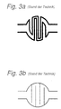
- Such a film pressure sensor is from the generic DE 42 37 072 C1 known and shown in Fig. 3a as a circuit diagram.
- the film pressure sensor is made of two laminated together Carrier films made of thermoplastic, of which the first with a semiconductor polymer and the second with two adjacent conductor tracks that can be contacted at both ends is coated.
- Within spatially delimited sensor elements Forming areas have non-contact conductors interlocking comb structures. Will the sensor element loaded with a normal force, the semiconductor material switches adjacent contact fingers of the comb structures more or less parallel depending on the force. Between there is an electrical resistance on both conductor tracks, which decreases with increasing pressure.
- the one from the generic Font known film pressure sensor is for safety-relevant Applications in motor vehicles, especially for seat occupancy detection designed.
- a continuity test measures the electrical Resistance of the conductor tracks that can be contacted at both ends.
- the continuity test can, for example, in the course of a automatic test sequence every time the vehicle is started or in specified intervals. Through the special training the contact fingers forming the comb structure as conductor track loops the contact fingers are fully included in the test.
- the generic film pressure sensor in Fig. 3a represents the development dar a simple film pressure sensor, as in 3b is shown and for example from DE 30 44 384 A1 can be derived.
- the comb structure is through Realized branch lines branching vertically from a main line.
- the object of the invention is to provide a film pressure sensor, which can be designed with a low impedance and with a predefined one Area as high a sensitivity as possible at the same time verifiability allowed.
- the film pressure sensor according to the invention differs from the film pressure sensor from the generic font in that the sensor element in addition to the as conductor track loops trained contact fingers also has those that as Stub lines are formed.
- the stub lines take up less space than the conductor loop loops, so that the sensitivity increases with the same area is when one or more conductor loops through Stub lines are replaced. At the same time it decreases by saving on conductor loop loops, the conductor resistance, so that the desired low-resistance design of the conductor track structure is achieved.
- a rough checkability of the sensor element is indispensable, and according to the invention with a few as conductor track loops trained contact fingers ensured. With a Such an arrangement will cause any major crack from the extension of the Sensor element and a thickness that is not under pressure is bridged, detected during a continuity test.
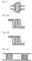
- the film pressure sensor in Fig. 1 consists of a single one circular sensor element 1.
- the comb-like structures are arranged opposite and facing each other and grab without contact.
- the contact fingers are formed by branch-free conductor loop loops 5, 5 'on the one hand and by stub lines branching vertically from the conductor tracks 3, 4 6, 6 'on the other hand.
- the conductor tracks 3, 4 are comparative designed to be thick in terms of evaluability a continuity test the total line resistance is low to keep.
- the stub lines 6, 6 ' can be comparatively be thin as they pass the continuity test do not participate.
- a thin version also has the advantage that the sensitivity of the sensor element is increased can be made by more stub lines 6, 6 'on the same area can be accommodated, as can also be seen from FIG. 1.
- the position 7 indicates a typical crack course in FIG. 1, which extends over several contact fingers. There a contact fingers formed by a conductor loop loop 5 are also detected the crack is detected during a continuity test. On such a crack, would remain with a sensor element after State of the art, Fig. 3b, in which the comb-like structures formed solely by stub lines, undetected.
- the order and distribution of the conductor loop 5, 5 'within of the sensor element 1 defines the size and extent of the cracks that are recognized by means of a continuity test. On sufficiently strong cracks can not only be in the unloaded state but can also be reliably recognized under pressure. A thin crack, on the other hand, would result in pressure loading from semiconductor material bridged and would therefore only be in the unloaded state reliably recognizable.
- An advantageous embodiment provides, as shown in FIG. 1, the outer contact fingers closed by conductor loops form and the so limited inner area with as stub lines to fill up trained contact fingers. With this arrangement are cracks that originate outside the sensor element have and expand with time, early on Reaching the sensor element detected.
- 2c shows two sensor elements connected in series 1, 1 ', in which, based on a single sensor element 1 a conductor track 3 a first, exclusively from stub lines 6 formed comb structure and the other conductor track 4 a second, Comb structure formed exclusively from conductor loop loops 5 ' having. This means that a loop 5 ' trained contact finger next to a trained as a stub 6 Contact fingers of the other conductor track arranged.
- a following sensor element 1 ' has the reverse arrangement by moving the first and second comb structure from the respective other conductor track are formed.
- the following sensor element 1 'thus has one conductor track 3, the comb structure of which previously stub lines 6 now had conductor loop loops 5, while the comb structure of the other conductor track 4 now stub lines 6 '.
- the volume resistance is even on the two conductor tracks 3, 4 distributed what in evaluating the continuity test can be beneficial.
- a sensor element is shown, as it from the generic Scripture is known and which is a full review the comb structure allowed.
- 3b is a sensor element shown as it is also from the prior art (DE 30 44 384 A1) is known and in which the only as stub lines trained contact fingers from a continuity test cannot be recorded.
- FIGS. 4a, 4b show a film pressure sensor in cross section in which a stub 11 is interrupted.
- 4a is the sensor element is shown unloaded, in contrast it is loaded in FIG. 4b, clearly recognizable by the bent upper carrier film 8.
- the upper carrier film 8 and the lower carrier film 10 are laminated together using a double-sided adhesive film.
- limited pressure sensitive area is the middle Cut out adhesive film and thus serves as a spacer (Spacer) 9, the conductor tracks in the unloaded state and Stub 11 from the underlying semiconductor polymer layer 12 separates.
- the force applied sensor element in Fig. 4b an interruption in a within the pressure sensitive area running line such as the branch line 11 through the Semiconductor polymer layer 12 with its specific resistance bridged depending on the force. This bridging is through resistance 13 represented symbolically. That leaves the interrupted one Cable largely functional because it is under load a missing piece of line is replaced by the resistor becomes. The sensor element is less affected, ever the break in the line is shorter.
Landscapes
- Physics & Mathematics (AREA)
- General Physics & Mathematics (AREA)
- Force Measurement Appropriate To Specific Purposes (AREA)
Description
- Fig. 1
- ein erstes Ausführungsbeispiel für einen erfindungsgemäßen Foliendrucksensor,
- Fig. 2
- weitere Ausführungsbeispiele,
- Fig. 3
- Leiterbahnstruktur bekannter Foliendrucksensoren,
- Fig. 4
- Querschnitt durch einen Foliendrucksensor ohne und mit Druckbelastung.
Claims (6)
- Foliendrucksensor aufgebaut aus zwei zusammenlaminierten Trägerfolien aus thermoplastischem Kunststoff, wobei die erste Trägerfolie mit einem Halbleiterpolymer und die zweite Trägerfolie mit zwei benachbarten, jeweils an beiden Enden kontaktierbaren Leiterbahnen beschichtet ist, die innerhalb räumlich abgegrenzter, Sensorelemente bildende Bereiche berührungslos ineinander greifende Kammstrukturen aufweisen, dadurch gekennzeichnet, daß innerhalb eines Sensorelementes (1, 1') mindestens ein Kontaktfinger der beiden Kammstrukturen durch eine Leiterbahnschlinge (5, 5') und mindestens ein anderer Kontaktfinger durch eine von einer Leiterbahn abzweigenden Stichleitung (6, 6', 8) gebildet ist.
- Foliendrucksensor nach Anspruch 1, dadurch gekennzeichnet, daß die äußeren Kontaktfinger eines Sensorelementes (1) durch Leiterbahnschlingen (5, 5') gebildet sind.
- Foliendrucksensor nach Anspruch 1, dadurch gekennzeichnet, daß die Stichleitungen (8) von der Leiterbahnschlinge (5, 5') abzweigen.
- Foliendrucksensor nach Anspruch 1, dadurch gekennzeichnet, daß jeweils ein als Leiterbahnschlinge (5, 5') ausgebildeter Kontaktfinger der einen Leiterbahn (3) neben einem als Stichleitung (6, 6') ausgebildeten Kontaktfinger der anderen Leiterbahn (4) angeordnet ist.
- Foliendrucksensor nach einem der Ansprüche 1 bis 4, dadurch gekennzeichnet, daß die beiden Trägerfolien (8, 10) mittels einer zwischenliegenden Klebefolie zusammenlaminiert sind, welche im Bereich des Sensorelementes ausgespart ist, wobei die Kontur (2) der Aussparung die Kammstrukturen in einem solchen Abstand umschließt, daß die Leiterbahnabschnitte der Kontaktfinger (5, 5', 6, 6', 8) bei Druckbelastung vollständig mit dem Halbleiterpolymer (12) in Berührung kommen.
- Foliendrucksensor nach einem der voranstehenden Ansprüche, dadurch gekennzeichnet, daß er bei einer sicherheitskritischen Anwendung wie zur Sitzbelegungserkennung in Kraftfahrzeugen eingesetzt ist.
Applications Claiming Priority (2)
| Application Number | Priority Date | Filing Date | Title |
|---|---|---|---|
| DE19530092A DE19530092A1 (de) | 1995-08-16 | 1995-08-16 | Überprüfbarer Foliendrucksensor |
| DE19530092 | 1995-08-16 |
Publications (3)
| Publication Number | Publication Date |
|---|---|
| EP0758741A2 EP0758741A2 (de) | 1997-02-19 |
| EP0758741A3 EP0758741A3 (de) | 1998-02-25 |
| EP0758741B1 true EP0758741B1 (de) | 2000-02-02 |
Family
ID=7769603
Family Applications (1)
| Application Number | Title | Priority Date | Filing Date |
|---|---|---|---|
| EP96110993A Expired - Lifetime EP0758741B1 (de) | 1995-08-16 | 1996-07-09 | Foliendrucksensor |
Country Status (4)
| Country | Link |
|---|---|
| US (1) | US6505521B1 (de) |
| EP (1) | EP0758741B1 (de) |
| JP (1) | JP2782336B2 (de) |
| DE (2) | DE19530092A1 (de) |
Cited By (1)
| Publication number | Priority date | Publication date | Assignee | Title |
|---|---|---|---|---|
| DE102004002479A1 (de) * | 2004-01-16 | 2005-08-11 | Siemens Ag | Schaltungsanordnung zur Sitzbelegungserkennung und Gurtwarnung in einem Kraftfahrzeug |
Families Citing this family (21)
| Publication number | Priority date | Publication date | Assignee | Title |
|---|---|---|---|---|
| DE19717273C1 (de) * | 1997-04-24 | 1998-07-30 | Volkswagen Ag | Vorrichtung mit einem Foliendrucksensor zur Sitzbelegungserkennung für einen Fahrzeugsitz |
| WO2003025961A1 (de) * | 2001-09-19 | 2003-03-27 | Iee International Electronics & Engineering S.A. | Schaltelement in folienbauweise |
| DE10205822A1 (de) * | 2002-02-13 | 2003-09-04 | Soehnle Waagen Gmbh & Co Kg | Messvorrichtung für eine Körperanalysewaage |
| EP1437584A1 (de) * | 2003-01-07 | 2004-07-14 | IEE INTERNATIONAL ELECTRONICS & ENGINEERING S.A. | Drucksensor mit elastischer Sensorschicht, deren Oberfläche mikrostrukturiert ist |
| US7187264B2 (en) * | 2003-02-20 | 2007-03-06 | Iee International Electronics & Engineering S.A. | Foil-type switching element with improved spacer design |
| ES2281000T3 (es) | 2003-06-23 | 2007-09-16 | IEE INTERNATIONAL ELECTRONICS & ENGINEERING S.A. | Sensor de ocupacion de asiento. |
| JP2005296415A (ja) * | 2004-04-13 | 2005-10-27 | Tanita Corp | 体組成測定装置 |
| JP4218614B2 (ja) * | 2004-08-27 | 2009-02-04 | アイシン精機株式会社 | 座席状態検出装置、車両用ヘッドランプの照射方向調節装置及び着座検出装置 |
| JP2006064572A (ja) * | 2004-08-27 | 2006-03-09 | Aisin Seiki Co Ltd | 座席状態検出装置、車両用ヘッドランプの照射方向調節装置及び着座検出装置 |
| LU91130B1 (en) * | 2005-01-26 | 2006-07-27 | Iee Sarl | Pressure sensitive element and seat sensor |
| FR2888789B1 (fr) * | 2005-07-20 | 2007-10-12 | Peugeot Citroen Automobiles Sa | Matelassure de siege de vehicule automobile et procede de realisation d'une telle matelassure |
| DE102005053744B3 (de) * | 2005-11-10 | 2006-12-28 | Lear Corp., Southfield | Verfahren zur Bestimmung eines äquivalenten Wertes für einen ausgefallenen Sensor in einem Fahrzeugsitz mit einem Besetzungsabfühlsystem |
| DE102007056238B4 (de) * | 2006-11-29 | 2012-05-31 | Denso Corporation | Lastsensor |
| DE202009012350U1 (de) | 2009-09-14 | 2010-04-22 | I.G. Bauerhin Gmbh | Drucksensor-Einheit |
| GB2484089A (en) * | 2010-09-29 | 2012-04-04 | Peratech Ltd | Dual action parallel sensor |
| US9442594B2 (en) | 2010-09-29 | 2016-09-13 | Peratech Holdco Limited | Resistance changing sensor |
| DE102013206450B4 (de) * | 2013-04-11 | 2016-09-01 | Lear Corporation | Sitzbelegungssensor und Herstellungsverfahren |
| DE102014007163B3 (de) * | 2014-05-15 | 2015-09-24 | Florian Gerber | Überwachungssystem für Kraftfahrzeuge |
| NL2014995B1 (en) * | 2015-06-19 | 2017-01-23 | Desso B V | System for forming a floor for detecting a pressure applied thereon, device for use in such system, flooring provided therewith and connection element for the device. |
| TWI673882B (zh) * | 2018-06-08 | 2019-10-01 | 台灣艾華電子工業股份有限公司 | 壓力感測器 |
| CN210864624U (zh) * | 2020-01-22 | 2020-06-26 | 湃瑞电子科技(苏州)有限公司 | 压力传感器及电子设备 |
Family Cites Families (13)
| Publication number | Priority date | Publication date | Assignee | Title |
|---|---|---|---|---|
| US3749866A (en) * | 1972-05-01 | 1973-07-31 | Amp Inc | Foam seat sensor |
| FR2420846A1 (fr) * | 1978-03-21 | 1979-10-19 | Thomson Csf | Structure semi-conductrice a avalanche comportant une troisieme electrode |
| GB2064873B (en) * | 1979-11-26 | 1984-09-05 | Eventoff Franklin Neal | Pressure sensitive electric switch |
| JPS595669A (ja) * | 1982-07-01 | 1984-01-12 | Hitachi Ltd | 半導体装置 |
| US4661664A (en) * | 1985-12-23 | 1987-04-28 | Miller Norman K | High sensitivity mat switch |
| US5010774A (en) * | 1987-11-05 | 1991-04-30 | The Yokohama Rubber Co., Ltd. | Distribution type tactile sensor |
| JP2658175B2 (ja) * | 1988-05-16 | 1997-09-30 | 日産自動車株式会社 | 半導体位置センサ |
| GB2222258A (en) * | 1988-07-29 | 1990-02-28 | David Coates | Tactile pressure sensor |
| JP2591799B2 (ja) * | 1988-08-12 | 1997-03-19 | 沖電気工業株式会社 | 半導体集積回路の欠陥検出方法及び欠陥検出用回路 |
| JPH02304826A (ja) * | 1989-05-19 | 1990-12-18 | S M K Kk | 着席検知装置 |
| JP2923813B2 (ja) * | 1991-06-11 | 1999-07-26 | キヤノン株式会社 | カンチレバー型変位素子、及びこれを用いた走査型トンネル顕微鏡、情報処理装置 |
| JPH0645423A (ja) * | 1992-07-22 | 1994-02-18 | Nec Kyushu Ltd | 半導体装置の試験方法 |
| DE4237072C1 (de) * | 1992-11-03 | 1993-12-02 | Daimler Benz Ag | Resistiver Foliendrucksensor |
-
1995
- 1995-08-16 DE DE19530092A patent/DE19530092A1/de not_active Ceased
-
1996
- 1996-07-09 EP EP96110993A patent/EP0758741B1/de not_active Expired - Lifetime
- 1996-07-09 DE DE59604353T patent/DE59604353D1/de not_active Expired - Fee Related
- 1996-08-01 JP JP8233524A patent/JP2782336B2/ja not_active Expired - Fee Related
-
1997
- 1997-09-08 US US08/924,941 patent/US6505521B1/en not_active Expired - Fee Related
Cited By (2)
| Publication number | Priority date | Publication date | Assignee | Title |
|---|---|---|---|---|
| DE102004002479A1 (de) * | 2004-01-16 | 2005-08-11 | Siemens Ag | Schaltungsanordnung zur Sitzbelegungserkennung und Gurtwarnung in einem Kraftfahrzeug |
| DE102004002479B4 (de) * | 2004-01-16 | 2007-12-27 | Siemens Ag | Schaltungsanordnung zur Sitzbelegungserkennung und Gurtwarnung in einem Kraftfahrzeug |
Also Published As
| Publication number | Publication date |
|---|---|
| EP0758741A2 (de) | 1997-02-19 |
| DE59604353D1 (de) | 2000-03-09 |
| US6505521B1 (en) | 2003-01-14 |
| JPH09119874A (ja) | 1997-05-06 |
| JP2782336B2 (ja) | 1998-07-30 |
| DE19530092A1 (de) | 1997-02-20 |
| EP0758741A3 (de) | 1998-02-25 |
Similar Documents
| Publication | Publication Date | Title |
|---|---|---|
| EP0758741B1 (de) | Foliendrucksensor | |
| DE69922673T2 (de) | Kraftsensor | |
| DE4237072C1 (de) | Resistiver Foliendrucksensor | |
| EP1636812B1 (de) | Drucksensor in folienbauweise | |
| DE3429250C1 (de) | Auf die Einwirkung einer Kraft ansprechender Sensor | |
| DE2732529C2 (de) | Gedruckte Schaltungsplatine | |
| EP0071031A2 (de) | Trägerelement für einen IC-Baustein | |
| EP3564015B1 (de) | Strukturbauteil sowie system und verfahren zur detektion von beschädigungen | |
| DE102004002479B4 (de) | Schaltungsanordnung zur Sitzbelegungserkennung und Gurtwarnung in einem Kraftfahrzeug | |
| EP0513715A1 (de) | Leitbahnanorndung für höchstintegrierte Schaltungen | |
| EP3743636B1 (de) | Belagverschleissmesseinrichtung für eine bremse, bremse und bremsbelagsatz | |
| EP1068501B1 (de) | Dehnungsempfindlicher widerstand | |
| EP0869250A2 (de) | Vorrichtung zur Einklemmerkennung bei einem kraftbetätigten Schliesselement | |
| EP1451043A1 (de) | Sensoranordnung | |
| DE19539181C2 (de) | Chipkartenmodul sowie entsprechendes Herstellungsverfahren | |
| DE20210025U1 (de) | Flachleiter | |
| EP1379849B1 (de) | Schaltungsanordnung mit mehreren sensorelementen in matrix-verschaltung | |
| DE102016219620A1 (de) | Leiterplatte mit einem gebogenen Verbindungsabschnitt und Verfahren zum Testen bzw. Herstellen derselben sowie elektronisches Steuergerät und Verfahren zum Betrieb desselben | |
| EP3472935B1 (de) | Kapazitive sensorvorrichtung mit verbesserter störtoleranz | |
| DE102008044115A1 (de) | Schaltelement, Busschaltsystem, Steuereinheit und Verfahren zum Erkennen von Schalterstellungen einer Mehrzahl von Schaltelementen | |
| DE102016005837B4 (de) | Druckempfindliches Sensor-System | |
| DE2227627A1 (de) | Abdeckung fuer das spulensystem eines metalldetektors | |
| DE102019116333A1 (de) | Elektrische leitungsanordnung mit einer art verdrillung und herstellungsverfahren | |
| EP0905828A2 (de) | Vorrichtung zur Identifizierung von elektronischen Geräten | |
| AT504406B1 (de) | Messvorrichtung |
Legal Events
| Date | Code | Title | Description |
|---|---|---|---|
| PUAI | Public reference made under article 153(3) epc to a published international application that has entered the european phase |
Free format text: ORIGINAL CODE: 0009012 |
|
| AK | Designated contracting states |
Kind code of ref document: A2 Designated state(s): DE FR GB IT SE |
|
| RAP1 | Party data changed (applicant data changed or rights of an application transferred) |
Owner name: I.E.E. INTERNATIONAL ELECTRONICS & ENGINEERING S. Owner name: DAIMLER-BENZ AKTIENGESELLSCHAFT |
|
| PUAL | Search report despatched |
Free format text: ORIGINAL CODE: 0009013 |
|
| AK | Designated contracting states |
Kind code of ref document: A3 Designated state(s): DE FR GB IT SE |
|
| 17P | Request for examination filed |
Effective date: 19980218 |
|
| RAP1 | Party data changed (applicant data changed or rights of an application transferred) |
Owner name: I.E.E. INTERNATIONAL ELECTRONICS & ENGINEERING S. Owner name: DAIMLERCHRYSLER AG |
|
| GRAG | Despatch of communication of intention to grant |
Free format text: ORIGINAL CODE: EPIDOS AGRA |
|
| GRAG | Despatch of communication of intention to grant |
Free format text: ORIGINAL CODE: EPIDOS AGRA |
|
| GRAH | Despatch of communication of intention to grant a patent |
Free format text: ORIGINAL CODE: EPIDOS IGRA |
|
| RTI1 | Title (correction) |
Free format text: SHEET PRESSURE SENSOR |
|
| 17Q | First examination report despatched |
Effective date: 19990712 |
|
| GRAH | Despatch of communication of intention to grant a patent |
Free format text: ORIGINAL CODE: EPIDOS IGRA |
|
| GRAA | (expected) grant |
Free format text: ORIGINAL CODE: 0009210 |
|
| ITF | It: translation for a ep patent filed | ||
| AK | Designated contracting states |
Kind code of ref document: B1 Designated state(s): DE FR GB IT SE |
|
| REF | Corresponds to: |
Ref document number: 59604353 Country of ref document: DE Date of ref document: 20000309 |
|
| ET | Fr: translation filed | ||
| GBT | Gb: translation of ep patent filed (gb section 77(6)(a)/1977) |
Effective date: 20000321 |
|
| PLBE | No opposition filed within time limit |
Free format text: ORIGINAL CODE: 0009261 |
|
| STAA | Information on the status of an ep patent application or granted ep patent |
Free format text: STATUS: NO OPPOSITION FILED WITHIN TIME LIMIT |
|
| 26N | No opposition filed | ||
| REG | Reference to a national code |
Ref country code: GB Ref legal event code: IF02 |
|
| PGFP | Annual fee paid to national office [announced via postgrant information from national office to epo] |
Ref country code: GB Payment date: 20050627 Year of fee payment: 10 |
|
| PGFP | Annual fee paid to national office [announced via postgrant information from national office to epo] |
Ref country code: FR Payment date: 20050712 Year of fee payment: 10 |
|
| PGFP | Annual fee paid to national office [announced via postgrant information from national office to epo] |
Ref country code: SE Payment date: 20050714 Year of fee payment: 10 Ref country code: DE Payment date: 20050714 Year of fee payment: 10 |
|
| PG25 | Lapsed in a contracting state [announced via postgrant information from national office to epo] |
Ref country code: GB Free format text: LAPSE BECAUSE OF NON-PAYMENT OF DUE FEES Effective date: 20060709 |
|
| PG25 | Lapsed in a contracting state [announced via postgrant information from national office to epo] |
Ref country code: SE Free format text: LAPSE BECAUSE OF NON-PAYMENT OF DUE FEES Effective date: 20060710 |
|
| PGFP | Annual fee paid to national office [announced via postgrant information from national office to epo] |
Ref country code: IT Payment date: 20060731 Year of fee payment: 11 |
|
| PG25 | Lapsed in a contracting state [announced via postgrant information from national office to epo] |
Ref country code: DE Free format text: LAPSE BECAUSE OF NON-PAYMENT OF DUE FEES Effective date: 20070201 |
|
| EUG | Se: european patent has lapsed | ||
| GBPC | Gb: european patent ceased through non-payment of renewal fee |
Effective date: 20060709 |
|
| REG | Reference to a national code |
Ref country code: FR Ref legal event code: ST Effective date: 20070330 |
|
| PG25 | Lapsed in a contracting state [announced via postgrant information from national office to epo] |
Ref country code: FR Free format text: LAPSE BECAUSE OF NON-PAYMENT OF DUE FEES Effective date: 20060731 |
|
| PG25 | Lapsed in a contracting state [announced via postgrant information from national office to epo] |
Ref country code: IT Free format text: LAPSE BECAUSE OF NON-PAYMENT OF DUE FEES Effective date: 20070709 |