EP0757223B1 - Conteneur combustible de charge propulsive pour une munition d'artillerie - Google Patents
Conteneur combustible de charge propulsive pour une munition d'artillerie Download PDFInfo
- Publication number
- EP0757223B1 EP0757223B1 EP96401343A EP96401343A EP0757223B1 EP 0757223 B1 EP0757223 B1 EP 0757223B1 EP 96401343 A EP96401343 A EP 96401343A EP 96401343 A EP96401343 A EP 96401343A EP 0757223 B1 EP0757223 B1 EP 0757223B1
- Authority
- EP
- European Patent Office
- Prior art keywords
- container
- envelope
- combustible
- container according
- powder
- Prior art date
- Legal status (The legal status is an assumption and is not a legal conclusion. Google has not performed a legal analysis and makes no representation as to the accuracy of the status listed.)
- Expired - Lifetime
Links
- 239000000843 powder Substances 0.000 claims description 42
- 239000003380 propellant Substances 0.000 claims description 11
- 239000000463 material Substances 0.000 claims description 5
- 238000007373 indentation Methods 0.000 claims 3
- 230000037431 insertion Effects 0.000 claims 3
- 238000003780 insertion Methods 0.000 claims 3
- 239000000446 fuel Substances 0.000 description 7
- 239000000020 Nitrocellulose Substances 0.000 description 2
- 238000005194 fractionation Methods 0.000 description 2
- 238000004519 manufacturing process Methods 0.000 description 2
- 238000000465 moulding Methods 0.000 description 2
- 229920001220 nitrocellulos Polymers 0.000 description 2
- 230000002441 reversible effect Effects 0.000 description 2
- 238000002485 combustion reaction Methods 0.000 description 1
- 239000002360 explosive Substances 0.000 description 1
- 239000000945 filler Substances 0.000 description 1
- 238000010304 firing Methods 0.000 description 1
- 238000000034 method Methods 0.000 description 1
- 230000002093 peripheral effect Effects 0.000 description 1
- 230000001141 propulsive effect Effects 0.000 description 1
Images

Classifications
-
- F—MECHANICAL ENGINEERING; LIGHTING; HEATING; WEAPONS; BLASTING
- F42—AMMUNITION; BLASTING
- F42B—EXPLOSIVE CHARGES, e.g. FOR BLASTING, FIREWORKS, AMMUNITION
- F42B5/00—Cartridge ammunition, e.g. separately-loaded propellant charges
- F42B5/38—Separately-loaded propellant charges, e.g. cartridge bags
-
- Y—GENERAL TAGGING OF NEW TECHNOLOGICAL DEVELOPMENTS; GENERAL TAGGING OF CROSS-SECTIONAL TECHNOLOGIES SPANNING OVER SEVERAL SECTIONS OF THE IPC; TECHNICAL SUBJECTS COVERED BY FORMER USPC CROSS-REFERENCE ART COLLECTIONS [XRACs] AND DIGESTS
- Y10—TECHNICAL SUBJECTS COVERED BY FORMER USPC
- Y10S—TECHNICAL SUBJECTS COVERED BY FORMER USPC CROSS-REFERENCE ART COLLECTIONS [XRACs] AND DIGESTS
- Y10S102/00—Ammunition and explosives
- Y10S102/70—Combustilbe cartridge
Definitions
- the invention relates to a fuel container of propellant charge for artillery ammunition of countryside.
- artillery ammunition from campaign is carried out in two parts, one consisting of a projectile, for example of the incendiary, explosive type, lighting, etc ..., and the other by a propellant charge.
- the propellant charge is most often divided so that you can adjust the range of the projectile according to the military strategy applied. He is known to carry out this fractionation in the form of gargousses each consisting of a canvas bag containing a amount of propellant powder, but we now see increasingly appear a fractionation in the form of combustible containers. By playing on the number of gargoyles or containers (from 1 to 6), we modify the quantity of powder used and the scope of the shoot.
- live powders with gas flow relatively large are perfectly suited for short-range shots, when they aren't long-range shots.
- Combustible containers are for example described in documents WO-A-8500433 and EP-A-475 207.
- WO-A-8500433 describes charging modules propellant in the form of filled fuel containers powder, with an axial channel in which is placed a ignition charge.
- EP-A-475 207 describes a container fuel which consists of two shell parts nested one inside the other, with a central channel containing an ignition aid charge.
- the filler is a compacted slow powder and the outer surface of the container has an asperity likely to cause problems during the phase weapon feed.
- the object of the invention is to provide a container fuel usable in field artillery for perform short-range shots without modify the weapon loading mechanism.
- the means of reducing the interior volume of the container also form the means to be able to differentiate the container of a conventional container.
- the container is made up a central shaft, a coaxial side casing and concentric on the outside with the central barrel, a bottom and a cover, the means for reducing the internal volume of the container being located at its envelope, its bottom and / or its cover.
- the means for reducing the interior volume of the container are formed by a constriction formed at the level of the container shell, this constriction being for example achieved by reducing the diameter of the central part of the container shell.
- the bottom and the cover are two substantially annular pieces identical which have two circular edges internal and external by means of which they are nested between the central barrel and the envelope, this assembly by interlocking being a tight fitting which is possibly completed by a bonding operation.
- the bottom and the lid of the container do not can form only one piece.
- the envelope of the container is formed of two coaxial sections, axially aligned with each other and assembled to each other by snug fit socket.
- each section comprises a first cylindrical part in which just fits the bottom or the lid of the container, and a second cylindrical part of reduced diameter forming part of the neck, these first and second parts being connected to each other by a connecting wall of overall frustoconical shape.
- the end of the second cylindrical part of reduced diameter of one of the sections of the envelope shows a slight increase in diameter forming a skirt in which the second part fits cylindrical of reduced diameter of the other section.
- the two sections of the envelope are substantially identical.
- the second part cylindrical of reduced diameter of each section includes a half envelope with a slight increase of diameter towards its free end to form a half-skirt in which comes to fit the half-envelope of the other section which is not provided with the half-skirt.
- the means of reduction of the interior volume of the container are constituted by at least one impression made in the background and / or the cover, this imprint delimiting a boss which makes protruding inside the container, this imprint being in the form of an annular groove centered around the barrel central, for example.
- the envelope of the container is cylindrical, and the bottom and lid are two similar annular pieces with flanges internal and external circulars by means of which they are assembled by interlocking between the envelope and the barrel central.
- the barrel, the bottom and the envelope of the container can only form one piece.
- the means of reducing the interior volume of the container also include inner shims made of a material fuel for setting the live powder in the form of grains, when the interior volume of the container is only partially filled.
- an inner block is by example constituted by a cylinder mounted coaxially to the bole central by taking support against the means of reduction of the interior volume of the container, the live powder being loaded on the side of the central barrel.
- the live powder used is present in the form of grains, sticks or strands pre-divided, and the container is made of a material fuel such as cardboard loaded with nitrocellulose with a thickness of the order of 3 mm.
- the container can be taken over by the device automatic loading which equips artillery with campaign to allow them to perform either long or short range shots.
- the servant can easily differentiate this type day and night container versus a slow powder container of same footprint which does not have characteristics of shape such as those envisaged in the invention for reduce the interior volume of the container.
- the container is reversible, i.e. there is no need to distinguish a front or rear end before proceed to its loading.
- the container can be made with a reduced number of parts produced by molding, which allows simplification tools and therefore reduce the manufacturing cost.
- the live powder containers according to the invention and as shown schematically in the various figures present the same footprint as conventional powder containers used in ammunition from an artillery campaign that carries out long-range shots, i.e. that they have roughly the same dimensions in height and outside diameter than that of a container classic so that a field artillery could also perform short-range shots.
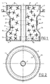
- a container 1 in general and in all modes of embodiment which will be described, consists of several parts, namely: a central shaft 2 whose height here defines the height of the container, a side envelope 3 overall cylindrical, coaxial and concentric outside the barrel 2, a 4 at one end and a bottom cover 5 at the other end. These different parts, once assembled the to each other, delimit between them an interior volume 7 of annular shape and intended to contain powder lively.
- these containers 1 Since for the same size, these containers 1 will be loaded with a quantity of powder less than the amount of slow powder loaded in a conventional container, the interior volume 7 of these containers will be reduced using the means hereinafter means for reducing the interior volume of the container.
- the means for reducing the interior volume 7 of a container 1 are constituted by a constriction R formed at level of the lateral envelope 3 of the container.
- the central barrel 2 and the bottom 4 of the container are one piece. More specifically, a end of central shaft 2 extends radially towards the exterior by a flat and shaped bottom wall 8 annular. The external peripheral part of the wall of bottom 8 is bordered by a side wall which forms a circular edge 9.
- the cover 5 is constituted by a bottom wall 10 flat and annular.
- This bottom wall 10 is internally and externally bordered by two walls lateral which extend on the same side of the bottom wall 10 and parallel to the axis of the central shaft 2 to form respectively a circular internal rim 11 and a rim external circular 12.
- the inside diameter of the rim internal circular 11 is adjusted to the outside diameter of the bole 2, while the outside diameter of the rim external circular 12 is substantially equal to that of circular edge 9 of the bottom 4.
- the second part cylindrical 17 of the section 3a has an increase of diameter from a rim 20 to form a skirt 22 whose inside diameter is adjusted to the outside diameter of the second cylindrical part 17 of the other section 3b.
- the skirt 22 can be provided on the section 3b.
- the container 1 therefore comprises four parts, in the occurrence: the central bole 2 extended at one end by the bottom 4, two sections 3a and 3b which form the envelope 3, and the cover 5. These four parts are manufactured by molding and their assembly is carried out as described below.
- the section 3a of the envelope 3 of the container is attached around the central bole 2 so that the rim 9 of the bottom 4 comes to fit together by an adjustment clamped in the cylindrical part 15 of the section 3a.
- section 3b of the envelope 3 of the container is attached around the central barrel 2 of so that its cylindrical part 17 in diameter reduced comes fit by a tight fit in the skirt 22 of the envelope section 3a previously assembled to bottom 4 of the container.
- the interior volume 7 of the container is responsible for live powder according to methods which will be specified more away, and is then closed by means of the cover 5 which fits together with a tight fit between the barrel central 2 and the envelope section 3b by means of its two internal 11 and external 12 circular edges.
- the assembly operations of the different parts of the container 1 can be improved by operations collage, known per se.
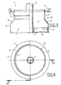
- a second embodiment illustrated on the Figures 3 and 4 differs from the previous one essentially in the means used to assemble between the two envelope sections 3a and 3b.
- the cylindrical part 17 of diameter reduced from the envelope section 3b comprises a skirt 24 which only extends over a half circumference and, in a way symmetrical, the cylindrical part 17 of reduced diameter by the other section 3a also includes a half-skirt 24 which only extends over a half circumference.
- the two envelope sections 3a and 3b have identical shapes but each of them presents an asymmetry compared to the axis of the central shaft 2, asymmetry which disappears when the two envelope sections 3a and 3b are assembled one to the other by interlocking. Such an assembly allows reduce the number of parts making up a container.
- the envelope 3 of the container is formed in a single piece which comprises a first cylindrical part 15 at each end, a central cylindrical part 17 of reduced diameter and two connecting walls 19 overall tapered between the two parts 15 and 17.
- the bottom 4 is dissociated from the central barrel 2, that is to say that the bottom 4 is substantially identical to the cover 5 and has an internal circular rim 11 and external circular rim 12 by means of which the bottom 4 just fits between the central barrel 2 and the casing 3.
- the constriction R formed by a reduction in diameter from the central part of the envelope 3 gives the container a coil shape that allows it to be differentiated immediately both visually and tactually, by compared to a slow powder container of the same size whose lateral envelope is perfectly cylindrical.
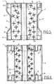
- the means for reducing the interior volume 7 of the container 1 consist of at least one fingerprint E made in the bottom and / or the lid of the container.
- the container 1 comprises a central barrel 2, a cylindrical side shell 3 coaxial and concentric externally in barrel 2, a cover 5 with a wall of annular bottom 10 bordered on each side by a rim internal circular 11 and an external circular rim 12, and a bottom 4 with an annular bottom wall 8 bordered by each side by an internal circular rim 11 and a external circular rim 12.
- An imprint E is made in the bottom wall 8 from the bottom 4 and into the bottom wall 10 of the cover 5.
- Each imprint E in the form of an annular groove 25 which delimits a boss which projects inside the container volume 7.
- the container 1 does not differ from that shown in the Figure 6 that by the fact that the central barrel 2, the wall of bottom 4 and the cylindrical lateral envelope 3 do not form only one piece to limit the number of pieces to two to assemble. Alternatively, this number could be three by separating the envelope 3 and the bottom 4 of the container.
- the interior volume 7 of the container has a carrying capacity, for a given size of the container, which is a function the number, shape and depth of the footprints E. These give the container a crown shape which differentiates it both visually and tactile, compared to a slow powder container, the bottom and / or the cover do not have such fingerprints.
- the live powder which is loaded in the container can come under the form of grains, sticks or pre-divided strands, and the container is advantageously made of a material fuel like cardboard loaded with nitrocellulose, for example.
- the internal volume 7 of the container 1 can be completely or partially filled. Unlike complete filling, as illustrated in FIG. 1, partial filling requires the presence of additional means for reducing the internal volume 7 of the container 1 to wedge the grains of powder g and ensure the cohesion of the container 1.
- these means consist of at least one inner block 30 made of a combustible material, this block 30 being mounted inside the container 1 so that the grains of powder g are preferably in contact with the central barrel 2.
- the wedge 30 is for example a tube mounted coaxially with the barrel 2 bearing against the cylindrical part 17 of reduced diameter of the casing 3 of the container 1 (FIG. 5) or against the side wall of the groove 25 ( figure 6).
- shims may prove to be necessary in the case where, for the same container and for the same powder characteristics, the mass and the volume of this powder may be different according to the production batches.
- the central barrel 2 of the container is intended to contain an ignition charge, in a way known per se, and it is for this reason that, in the case of the presence of internal shims 30, the loading of powder is advantageously located on the side of the central barrel 2 of the container 1.
- the height of the circular edges of the bottom 4 and the cover 5 is adjusted so as to give the container with sufficient rigidity or robustness, and the container is perfectly reversible, i.e. it can be loaded either end (side bottom) or the other end (cover side).
Landscapes
- Engineering & Computer Science (AREA)
- General Engineering & Computer Science (AREA)
- Closures For Containers (AREA)
- Details Of Rigid Or Semi-Rigid Containers (AREA)
- Packages (AREA)
Description
- présente le même encombrement qu'un conteneur classique de charge propulsive à poudre lente et utilisé pour effectuer des tirs de longue portée,
- comprend des moyens de réduction de son volume intérieur pour renfermer la quantité de poudre vive nécessaire pour que l'artillerie de campagne soit également utilisée pour effectuer des tirs de courte portée, et
- comprend des moyens pour pouvoir le différencier visuellement et tactilement d'un conteneur classique à poudre lente.
- la figure 1 est une vue en coupe longitudinale d'un premier mode de réalisation du conteneur selon l'invention,
- la figure 2 est une vue en coupe suivant la ligne II-II de la figure 1,
- la figure 3 est une vue en coupe suivant la ligne III-III de la figure 4 d'un second mode de réalisation du conteneur selon l'invention,
- la figure 4 est une vue en coupe suivant la ligne IV-IV de la figure 3,
- la figure 5 est une vue en coupe longitudinale d'un troisième mode de réalisation du conteneur selon l'invention,
- la figure 6 est une vue en coupe longitudinale d'un quatrième mode de réalisation du conteneur selon l'invention,
- la figure 7 est une vue en coupe longitudinale d'un cinquième mode de réalisation du conteneur selon l'invention, et
- la figure 8 est une vue en coupe suivant la ligne VIII-VIII de la figure 7.
- une première partie cylindrique 15 dont le diamètre extérieur délimite le diamètre du conteneur 1 et il est égal au diamètre extérieur d'un conteneur classique à poudre lente, et dont le diamètre intérieur est sensiblement ajusté au diamètre extérieur du rebord circulaire 9 du fond 4 ou du rebord circulaire externe 12 du couvercle 5,
- une seconde partie cylindrique 17 de diamètre réduit et qui forme une partie du rétreint R, et
- une troisième partie de liaison 19 de forme tronconique qui relie les parties cylindriques 15 et 17.
Claims (17)
- Conteneur combustible de charge propulsive pour une munition d'artillerie de campagne, caractérisé en ce que la charge propulsive est une poudre à combustion vive, et en ce que le conteneur :présente le même encombrement qu'un conteneur classique de charge propulsive à poudre de combustion lente et utilisé pour effectuer des tirs à longue portée,comprend des moyens de réduction (R, E) de son volume intérieur (7) pour renfermer la quantité de poudre vive nécessaire pour que l'artillerie de campagne soit également utilisée pour effectuer des tirs de courte portée, etcomprend des moyens (R, E) pour pouvoir le différencier visuellement et/ou tactilement d'un conteneur classique à poudre lente.
- Conteneur combustible selon la revendica-tion 1, caractérisé en ce que les moyens de réduction (R, E) du volume intérieur du conteneur forment également les moyens pour pouvoir différencier le conteneur d'un conteneur classique.
- Conteneur combustible selon la revendica-tion 1 ou 2, caractérisé en ce qu'il est constitué d'un fût central (2), d'une enveloppe latérale (3) cylindrique, coaxiale et concentrique extérieurement au fût central (2), un fond (4) et un couvercle (5), et en ce que les moyens de réduction (R, E) du volume intérieur (7) du conteneur sont situés au niveau de son enveloppe (3), de son fond (4), et/ou de son couvercle (5).
- Conteneur combustible selon la revendica-tion 3, caractérisé en ce que les moyens de réduction du volume intérieur (7) du conteneur sont constitués par un rétreint (R) formé au niveau de l'enveloppe (3) du conteneur.
- Conteneur combustible selon la revendica-tion 4, caractérisé en ce que le rétreint (R) est réalisé par une réduction du diamètre de la partie centrale de l'enveloppe (3) du conteneur.
- Conteneur combustible selon la revendica-tion 5, caractérisé en ce que le fond (4) et le couvercle (5) du conteneur sont deux pièces semblables, annulaires et pourvues de rebords circulaires interne (11) et externe (12) au moyen desquels ils sont assemblés par emboítement entre l'enveloppe (3) et le fût central (2).
- Conteneur combustible selon la revendica-tion 6, caractérisé en ce que le fût central (2) et le fond (4) du conteneur ne forment qu'une seule pièce.
- Conteneur combustible selon l'une quel-conque des revendications 4 à 7, caractérisé en ce que l'enveloppe (3) du conteneur est formée de deux tronçons (3a, 3b), coaxiaux, axialement alignés l'un avec l'autre et assemblés l'un à l'autre par emboítement.
- Conteneur combustible selon la revendica-tion 8, caractérisé en ce que chaque tronçon d'enveloppe (3a, 3b) comprend une première partie cylindrique (15) dans laquelle vient s'emboíter le fond (4) ou le couvercle (5), et une seconde partie cylindrique (17) de diamètre réduit formant une partie du rétreint (R), ces première et seconde parties (15, 16) étant reliées l'une à l'autre par une paroi de liaison (19) globalement tronconique.
- Conteneur combustible selon la revendica-tion 9, caractérisé en ce que l'extrémité de la seconde partie cylindrique (17) de diamètre réduit de l'un des deux tronçons d'enveloppe (3a, 3b) présente une augmentation de diamètre formant une jupe (22) dans laquelle vient s'emboíter la seconde partie cylindrique (17) de l'autre tronçon d'enveloppe.
- Conteneur combustible selon la revendica-tion 8, caractérisé en ce que la seconde partie cylindrique (17) de diamètre réduit de chaque tronçon d'enveloppe (3a, 3b) comprend une demi-enveloppe ayant une légère augmentation de diamètre vers son extrémité libre pour former une demi-jupe (24) dans laquelle vient s'emboíter la demi-enveloppe de l'autre tronçon non pourvu de la demi-jupe.
- Conteneur combustible selon la revendica-tion 3, caractérisé en ce que les moyens de réduction du volume intérieur (7) du conteneur sont constitués par au moins une empreinte (E) réalisée dans le fond (4) et/ou le couvercle (5), cette empreinte (E) délimitant un bossage qui fait saillie à l'intérieur du conteneur.
- Conteneur combustible selon la revendica-tion 12, caractérisé en ce que l'empreinte (E) est sous la forme d'une gorge annulaire (25).
- Conteneur combustible selon la revendica-tion 12 ou 13, caractérisé en ce que l'enveloppe (3) est cylindrique, et en ce que le fond (4) et le couvercle (5) sont deux pièces semblables pourvues de rebords circulaires respectivement interne (11) et externe (12) au moyen desquels ils sont assemblés par emboítement entre l'enveloppe (3) et le fût central (2).
- Conteneur combustible selon la revendica-tion 12 ou 13, caractérisé en ce que le fût central (2), le fond (4) et l'enveloppe (3) du conteneur forment une seule pièce, le couvercle (5) étant muni de deux rebords circulaires respectivement interne (11) et externe (12) au moyen desquels il est assemblé par emboítement entre le fût central (2) et l'enveloppe (3).
- Conteneur combustible selon l'une quel-conque des revendications précédentes, caractérisé en ce que les moyens de réduction (R, E) du volume intérieur (7) du conteneur comprennent également des cales intérieures (30) en un matériau combustible pour caler la poudre vive sous la forme de grains, lorsque le volume intérieur (7) du conteneur n'est que partiellement rempli.
- Conteneur combustible selon la revendication 16, caractérisé en ce qu'une cale intérieure (30) est constituée par un cylindre monté coaxialement au fût central (2) en prenant appui contre les moyens de réduction (R, E) du volume intérieur (7) du conteneur, la poudre vive étant chargée du côté du fût central (2).
Applications Claiming Priority (2)
| Application Number | Priority Date | Filing Date | Title |
|---|---|---|---|
| FR9508245 | 1995-07-07 | ||
| FR9508245A FR2736425B1 (fr) | 1995-07-07 | 1995-07-07 | Conteneur combustible de charge propulsive pour une munition d'artillerie de campagne |
Publications (2)
| Publication Number | Publication Date |
|---|---|
| EP0757223A1 EP0757223A1 (fr) | 1997-02-05 |
| EP0757223B1 true EP0757223B1 (fr) | 1999-08-25 |
Family
ID=9480796
Family Applications (1)
| Application Number | Title | Priority Date | Filing Date |
|---|---|---|---|
| EP96401343A Expired - Lifetime EP0757223B1 (fr) | 1995-07-07 | 1996-06-20 | Conteneur combustible de charge propulsive pour une munition d'artillerie |
Country Status (6)
| Country | Link |
|---|---|
| US (1) | US5726379A (fr) |
| EP (1) | EP0757223B1 (fr) |
| DE (1) | DE69603923T2 (fr) |
| FR (1) | FR2736425B1 (fr) |
| IL (1) | IL118767A (fr) |
| ZA (1) | ZA965601B (fr) |
Families Citing this family (4)
| Publication number | Priority date | Publication date | Assignee | Title |
|---|---|---|---|---|
| SE519296C2 (sv) * | 1997-08-14 | 2003-02-11 | Bofors Defence Ab | Drivladdningsmodul |
| FR2781879A1 (fr) | 1998-07-30 | 2000-02-04 | Giat Ind Sa | Element de charge propulsive et son procede de fabrication |
| RU2717569C1 (ru) * | 2019-11-27 | 2020-03-24 | Федеральное государственное унитарное предприятие "Центральный научно-исследовательский институт химии и механики" (ФГУП "ЦНИИХМ") | Метательный заряд для выстрела раздельного заряжания |
| FR3115869B1 (fr) * | 2020-11-04 | 2022-11-11 | Eurenco France | Procede de fabrication d'un boitier renfermant un chargement pyrotechnique |
Family Cites Families (8)
| Publication number | Priority date | Publication date | Assignee | Title |
|---|---|---|---|---|
| US788266A (en) * | 1904-04-09 | 1905-04-25 | Thomas S King | Short-range or gallery cartridge. |
| FR1514293A (fr) * | 1967-01-11 | 1968-02-23 | France Etat | éléments de charges propulsives pour munitions d'artillerie |
| DE8407198U1 (de) * | 1984-03-09 | 1984-08-30 | Rheinmetall GmbH, 4000 Düsseldorf | Treibladungsbehaelter |
| DE3924986A1 (de) * | 1989-07-28 | 1991-01-31 | Rheinmetall Gmbh | Treibladungsbehaelter |
| EP0475207B1 (fr) * | 1990-08-30 | 1995-08-09 | Olin Corporation | Charge modulaire de munition unitaire sans douile |
| US5269224A (en) * | 1990-08-30 | 1993-12-14 | Olin Corporation | Caseless utilized ammunition charge module |
| FR2710976B1 (fr) * | 1993-10-05 | 1995-11-17 | Poudres & Explosifs Ste Nale | Eléments de conteneurs combustibles pour munitions d'artillerie, procédé de fabrication et utilisation de tels éléments. |
| FR2714168B1 (fr) * | 1993-12-22 | 1996-02-09 | Giat Ind Sa | Procédé de fabrication de conteneur pour charge propulsive et conteneur ainsi obtenu. |
-
1995
- 1995-07-07 FR FR9508245A patent/FR2736425B1/fr not_active Expired - Fee Related
-
1996
- 1996-06-20 DE DE69603923T patent/DE69603923T2/de not_active Expired - Lifetime
- 1996-06-20 EP EP96401343A patent/EP0757223B1/fr not_active Expired - Lifetime
- 1996-06-27 US US08/670,557 patent/US5726379A/en not_active Expired - Fee Related
- 1996-07-01 IL IL11876796A patent/IL118767A/xx not_active IP Right Cessation
- 1996-07-02 ZA ZA965601A patent/ZA965601B/xx unknown
Also Published As
| Publication number | Publication date |
|---|---|
| FR2736425A1 (fr) | 1997-01-10 |
| EP0757223A1 (fr) | 1997-02-05 |
| IL118767A (en) | 1999-12-22 |
| US5726379A (en) | 1998-03-10 |
| DE69603923T2 (de) | 2000-03-30 |
| IL118767A0 (en) | 1996-10-31 |
| FR2736425B1 (fr) | 1997-08-29 |
| DE69603923D1 (de) | 1999-09-30 |
| ZA965601B (en) | 1997-04-16 |
Similar Documents
| Publication | Publication Date | Title |
|---|---|---|
| EP0640205B1 (fr) | Etui pour munition de type telescopee | |
| EP0646762B1 (fr) | Eléments de conteneurs combustibles pour munitions d'artillerie, procédé de fabrication et utilisation de tels éléments | |
| EP0684443B1 (fr) | Dispositif permettant de solidariser deux conteneurs et conteneur associé un tel dispositif | |
| FR2526151A1 (fr) | Munition encartouchee constituee par un projectile et une douille combustible ou partiellement combustible reliee a celui-ci | |
| EP0502753B1 (fr) | Conteneur pouvant recevoir une charge propulsive | |
| EP1181498B1 (fr) | Tube allumeur pour une munition d'artillerie | |
| EP0180515A1 (fr) | Dispositif pour réduire la trainée des munitions et munitions aptes à le recevoir | |
| EP0314547B1 (fr) | Chargement propulsif pour munition comportant un projectile empenné ainsi que son procédé de réalisation | |
| EP0757223A1 (fr) | Conteneur combustible de charge propulsive pour une munition d'artillerie | |
| EP0660070A1 (fr) | Procédé de fabrication de conteneur pour charge propulsive et conteneur ainsi obtenu | |
| FR2679994A1 (fr) | Dispositif d'allumage de la charge propulsive d'une munition, notamment telescopee, et munition initiee par un tel dispositif d'allumage. | |
| FR2728675A1 (fr) | Cartouche avec une douille et un projectile a fleche | |
| EP4241038B1 (fr) | Procede de fabrication d'un boitier renfermant un chargement pyrotechnique | |
| EP0691520B1 (fr) | Dispositif solidarisant deux conteneurs et conteneur associé à un tel dispositif | |
| FR2713328A1 (fr) | Conteneur pour charge propulsive pouvant être rendu solidaire d'un autre conteneur. | |
| EP0754927B1 (fr) | Système d'allumage d'une charge propulsive notamment pour munition d'artillerie de campagne et son procédé de fabrication | |
| EP0395456B1 (fr) | Dispositif de liaison entre un premier et un deuxième tronçon de projectile gyrostabilisé | |
| FR2650388A1 (fr) | Perfectionnements apportes aux munitions destinees a etre tirees par une arme a canon lisse | |
| FR2719373A1 (fr) | Dispositif de propulsion à portées variables pour grenade anti-émeutes. | |
| FR2710975A1 (fr) | Elément de munition d'artillerie et munition obtenue par assemblage d'une pluralité de tels éléments. | |
| EP0170757A1 (fr) | Cartouche pour fusils de chasse | |
| FR2497335A1 (fr) | Gargousse pour munitions d'artillerie | |
| FR2633712A1 (fr) | Perfectionnement apporte aux munitions a etuis rechargeables | |
| EP1586852A1 (fr) | Munition sans douille et procede de montage d'une telle munition | |
| FR2683626A1 (fr) | Grenade generatrice de gaz reversible. |
Legal Events
| Date | Code | Title | Description |
|---|---|---|---|
| PUAI | Public reference made under article 153(3) epc to a published international application that has entered the european phase |
Free format text: ORIGINAL CODE: 0009012 |
|
| AK | Designated contracting states |
Kind code of ref document: A1 Designated state(s): BE DE GB SE |
|
| 17P | Request for examination filed |
Effective date: 19970308 |
|
| GRAG | Despatch of communication of intention to grant |
Free format text: ORIGINAL CODE: EPIDOS AGRA |
|
| GRAG | Despatch of communication of intention to grant |
Free format text: ORIGINAL CODE: EPIDOS AGRA |
|
| GRAH | Despatch of communication of intention to grant a patent |
Free format text: ORIGINAL CODE: EPIDOS IGRA |
|
| 17Q | First examination report despatched |
Effective date: 19990112 |
|
| GRAH | Despatch of communication of intention to grant a patent |
Free format text: ORIGINAL CODE: EPIDOS IGRA |
|
| GRAA | (expected) grant |
Free format text: ORIGINAL CODE: 0009210 |
|
| AK | Designated contracting states |
Kind code of ref document: B1 Designated state(s): BE DE GB SE |
|
| PG25 | Lapsed in a contracting state [announced via postgrant information from national office to epo] |
Ref country code: GB Free format text: LAPSE BECAUSE OF FAILURE TO SUBMIT A TRANSLATION OF THE DESCRIPTION OR TO PAY THE FEE WITHIN THE PRESCRIBED TIME-LIMIT Effective date: 19990825 |
|
| REF | Corresponds to: |
Ref document number: 69603923 Country of ref document: DE Date of ref document: 19990930 |
|
| GBV | Gb: ep patent (uk) treated as always having been void in accordance with gb section 77(7)/1977 [no translation filed] |
Effective date: 19990825 |
|
| PLBE | No opposition filed within time limit |
Free format text: ORIGINAL CODE: 0009261 |
|
| STAA | Information on the status of an ep patent application or granted ep patent |
Free format text: STATUS: NO OPPOSITION FILED WITHIN TIME LIMIT |
|
| PG25 | Lapsed in a contracting state [announced via postgrant information from national office to epo] |
Ref country code: BE Free format text: LAPSE BECAUSE OF NON-PAYMENT OF DUE FEES Effective date: 20000630 |
|
| 26N | No opposition filed | ||
| BERE | Be: lapsed |
Owner name: GIAT INDUSTRIES Effective date: 20000630 |
|
| PGFP | Annual fee paid to national office [announced via postgrant information from national office to epo] |
Ref country code: SE Payment date: 20100525 Year of fee payment: 15 Ref country code: DE Payment date: 20100610 Year of fee payment: 15 |
|
| REG | Reference to a national code |
Ref country code: SE Ref legal event code: EUG |
|
| REG | Reference to a national code |
Ref country code: DE Ref legal event code: R119 Ref document number: 69603923 Country of ref document: DE Effective date: 20120103 |
|
| PG25 | Lapsed in a contracting state [announced via postgrant information from national office to epo] |
Ref country code: DE Free format text: LAPSE BECAUSE OF NON-PAYMENT OF DUE FEES Effective date: 20120103 |
|
| PG25 | Lapsed in a contracting state [announced via postgrant information from national office to epo] |
Ref country code: SE Free format text: LAPSE BECAUSE OF NON-PAYMENT OF DUE FEES Effective date: 20110621 |