EP0756901B1 - Einrichtung und Verfahren für Beschichtung von Gegenständen unter Verwendung einer porösen elastischen Matrix - Google Patents
Einrichtung und Verfahren für Beschichtung von Gegenständen unter Verwendung einer porösen elastischen Matrix Download PDFInfo
- Publication number
- EP0756901B1 EP0756901B1 EP96305278A EP96305278A EP0756901B1 EP 0756901 B1 EP0756901 B1 EP 0756901B1 EP 96305278 A EP96305278 A EP 96305278A EP 96305278 A EP96305278 A EP 96305278A EP 0756901 B1 EP0756901 B1 EP 0756901B1
- Authority
- EP
- European Patent Office
- Prior art keywords
- pads
- coating
- resilient
- compression
- coated
- Prior art date
- Legal status (The legal status is an assumption and is not a legal conclusion. Google has not performed a legal analysis and makes no representation as to the accuracy of the status listed.)
- Expired - Lifetime
Links
- 238000000576 coating method Methods 0.000 title claims description 97
- 239000011248 coating agent Substances 0.000 title claims description 95
- 238000000034 method Methods 0.000 title claims description 14
- 239000011159 matrix material Substances 0.000 title 1
- 230000006835 compression Effects 0.000 claims description 30
- 238000007906 compression Methods 0.000 claims description 30
- 239000006260 foam Substances 0.000 claims description 28
- 239000000314 lubricant Substances 0.000 claims description 23
- 235000013870 dimethyl polysiloxane Nutrition 0.000 claims description 11
- 229920000435 poly(dimethylsiloxane) Polymers 0.000 claims description 11
- 239000004205 dimethyl polysiloxane Substances 0.000 claims description 10
- 230000007246 mechanism Effects 0.000 claims description 3
- 238000004891 communication Methods 0.000 claims description 2
- 239000012530 fluid Substances 0.000 claims description 2
- 238000011176 pooling Methods 0.000 claims 1
- 229920001296 polysiloxane Polymers 0.000 description 18
- 239000002904 solvent Substances 0.000 description 17
- 239000000463 material Substances 0.000 description 9
- 239000011800 void material Substances 0.000 description 9
- KYKAJFCTULSVSH-UHFFFAOYSA-N chloro(fluoro)methane Chemical compound F[C]Cl KYKAJFCTULSVSH-UHFFFAOYSA-N 0.000 description 6
- 238000005461 lubrication Methods 0.000 description 6
- 239000013065 commercial product Substances 0.000 description 5
- 239000011148 porous material Substances 0.000 description 5
- 229920005830 Polyurethane Foam Polymers 0.000 description 4
- 238000004519 manufacturing process Methods 0.000 description 4
- 239000011496 polyurethane foam Substances 0.000 description 4
- 230000035515 penetration Effects 0.000 description 3
- 230000002093 peripheral effect Effects 0.000 description 3
- 238000005245 sintering Methods 0.000 description 3
- CBENFWSGALASAD-UHFFFAOYSA-N Ozone Chemical compound [O-][O+]=O CBENFWSGALASAD-UHFFFAOYSA-N 0.000 description 2
- 238000011109 contamination Methods 0.000 description 2
- 230000006378 damage Effects 0.000 description 2
- 238000007598 dipping method Methods 0.000 description 2
- 230000000694 effects Effects 0.000 description 2
- 230000001050 lubricating effect Effects 0.000 description 2
- 229920002635 polyurethane Polymers 0.000 description 2
- 239000004814 polyurethane Substances 0.000 description 2
- 239000000047 product Substances 0.000 description 2
- 238000005507 spraying Methods 0.000 description 2
- 239000000853 adhesive Substances 0.000 description 1
- 230000001070 adhesive effect Effects 0.000 description 1
- 230000015572 biosynthetic process Effects 0.000 description 1
- 239000008280 blood Substances 0.000 description 1
- 210000004369 blood Anatomy 0.000 description 1
- 230000015556 catabolic process Effects 0.000 description 1
- 239000003086 colorant Substances 0.000 description 1
- 230000007423 decrease Effects 0.000 description 1
- 238000006731 degradation reaction Methods 0.000 description 1
- 230000008021 deposition Effects 0.000 description 1
- 238000010790 dilution Methods 0.000 description 1
- 239000012895 dilution Substances 0.000 description 1
- 238000009826 distribution Methods 0.000 description 1
- 239000006263 elastomeric foam Substances 0.000 description 1
- 238000000605 extraction Methods 0.000 description 1
- 238000009950 felting Methods 0.000 description 1
- 238000010438 heat treatment Methods 0.000 description 1
- 229930195733 hydrocarbon Natural products 0.000 description 1
- 150000002430 hydrocarbons Chemical class 0.000 description 1
- 238000002844 melting Methods 0.000 description 1
- 230000008018 melting Effects 0.000 description 1
- 239000002184 metal Substances 0.000 description 1
- 230000000813 microbial effect Effects 0.000 description 1
- 239000000203 mixture Substances 0.000 description 1
- 231100000252 nontoxic Toxicity 0.000 description 1
- 230000003000 nontoxic effect Effects 0.000 description 1
- 239000002245 particle Substances 0.000 description 1
- 239000000575 pesticide Substances 0.000 description 1
- 238000003825 pressing Methods 0.000 description 1
- 239000013557 residual solvent Substances 0.000 description 1
- 239000000523 sample Substances 0.000 description 1
- 238000002604 ultrasonography Methods 0.000 description 1
Images


Classifications
-
- B—PERFORMING OPERATIONS; TRANSPORTING
- B05—SPRAYING OR ATOMISING IN GENERAL; APPLYING FLUENT MATERIALS TO SURFACES, IN GENERAL
- B05C—APPARATUS FOR APPLYING FLUENT MATERIALS TO SURFACES, IN GENERAL
- B05C1/00—Apparatus in which liquid or other fluent material is applied to the surface of the work by contact with a member carrying the liquid or other fluent material, e.g. a porous member loaded with a liquid to be applied as a coating
- B05C1/02—Apparatus in which liquid or other fluent material is applied to the surface of the work by contact with a member carrying the liquid or other fluent material, e.g. a porous member loaded with a liquid to be applied as a coating for applying liquid or other fluent material to separate articles
- B05C1/022—Apparatus in which liquid or other fluent material is applied to the surface of the work by contact with a member carrying the liquid or other fluent material, e.g. a porous member loaded with a liquid to be applied as a coating for applying liquid or other fluent material to separate articles to the outer surface of hollow articles
-
- A—HUMAN NECESSITIES
- A61—MEDICAL OR VETERINARY SCIENCE; HYGIENE
- A61M—DEVICES FOR INTRODUCING MEDIA INTO, OR ONTO, THE BODY; DEVICES FOR TRANSDUCING BODY MEDIA OR FOR TAKING MEDIA FROM THE BODY; DEVICES FOR PRODUCING OR ENDING SLEEP OR STUPOR
- A61M5/00—Devices for bringing media into the body in a subcutaneous, intra-vascular or intramuscular way; Accessories therefor, e.g. filling or cleaning devices, arm-rests
- A61M5/178—Syringes
- A61M5/31—Details
- A61M5/32—Needles; Details of needles pertaining to their connection with syringe or hub; Accessories for bringing the needle into, or holding the needle on, the body; Devices for protection of needles
-
- B—PERFORMING OPERATIONS; TRANSPORTING
- B05—SPRAYING OR ATOMISING IN GENERAL; APPLYING FLUENT MATERIALS TO SURFACES, IN GENERAL
- B05C—APPARATUS FOR APPLYING FLUENT MATERIALS TO SURFACES, IN GENERAL
- B05C1/00—Apparatus in which liquid or other fluent material is applied to the surface of the work by contact with a member carrying the liquid or other fluent material, e.g. a porous member loaded with a liquid to be applied as a coating
- B05C1/02—Apparatus in which liquid or other fluent material is applied to the surface of the work by contact with a member carrying the liquid or other fluent material, e.g. a porous member loaded with a liquid to be applied as a coating for applying liquid or other fluent material to separate articles
-
- A—HUMAN NECESSITIES
- A61—MEDICAL OR VETERINARY SCIENCE; HYGIENE
- A61M—DEVICES FOR INTRODUCING MEDIA INTO, OR ONTO, THE BODY; DEVICES FOR TRANSDUCING BODY MEDIA OR FOR TAKING MEDIA FROM THE BODY; DEVICES FOR PRODUCING OR ENDING SLEEP OR STUPOR
- A61M5/00—Devices for bringing media into the body in a subcutaneous, intra-vascular or intramuscular way; Accessories therefor, e.g. filling or cleaning devices, arm-rests
- A61M5/178—Syringes
- A61M5/31—Details
- A61M5/315—Pistons; Piston-rods; Guiding, blocking or restricting the movement of the rod or piston; Appliances on the rod for facilitating dosing ; Dosing mechanisms
- A61M5/31511—Piston or piston-rod constructions, e.g. connection of piston with piston-rod
- A61M5/31513—Piston constructions to improve sealing or sliding
-
- A—HUMAN NECESSITIES
- A61—MEDICAL OR VETERINARY SCIENCE; HYGIENE
- A61M—DEVICES FOR INTRODUCING MEDIA INTO, OR ONTO, THE BODY; DEVICES FOR TRANSDUCING BODY MEDIA OR FOR TAKING MEDIA FROM THE BODY; DEVICES FOR PRODUCING OR ENDING SLEEP OR STUPOR
- A61M5/00—Devices for bringing media into the body in a subcutaneous, intra-vascular or intramuscular way; Accessories therefor, e.g. filling or cleaning devices, arm-rests
- A61M5/178—Syringes
- A61M5/31—Details
- A61M5/32—Needles; Details of needles pertaining to their connection with syringe or hub; Accessories for bringing the needle into, or holding the needle on, the body; Devices for protection of needles
- A61M5/329—Needles; Details of needles pertaining to their connection with syringe or hub; Accessories for bringing the needle into, or holding the needle on, the body; Devices for protection of needles characterised by features of the needle shaft
Definitions
- This invention relates to the coating of objects and more particularly relates to methods and apparatus for applying lubricants to medical devices such as over-the-needle peripheral venous catheters, hypodermic needles, blades and the like.
- Medical devices are often assembled from components formed from many different materials. It often is necessary to apply a coating of a lubricant to one or more of the components so that a component of one material will readily slide against a component of another material. Examples of this type of application are catheters with guidewires, over-needle catheters, syringe plunger stopper within a syringe barrel, needles for penetration of blood collection tube stoppers and the like. In other medical device applications, a lubricant is applied to a device to ease its penetration into the body. Examples of these applications are surgical blades, hypodermic needles, peripheral venous catheters and the like.
- a commonly used lubricant for medical devices is "silicone," i e., polydimethyl siloxane having a Brookfield viscosity between about 1,000 and 20,000 centistokes (cs).
- silicone is applied "neat", i.e., without solvent.
- An example of neat application of silicone to syringe plunger stoppers is disclosed in United States Patent 5,207,293 to Eden et al. This patent discloses a method and apparatus for lubricating syringe stoppers by moving the stoppers between a pair of wheels which are positioned partially in a reservoir containing lubricant so that with rotation of the wheels, lubricant is transferred to the stoppers.
- Another commonly used neat application method is tumbling a measured quantity of small parts, such as stoppers, with a measured quantity of lubricant so that the parts acquire a coating of the lubricant.
- Silicone lubricant also may be sprayed onto the parts either neat or in a carrier solvent. Neat spraying has been found to work well for interior surfaces such as inside syringe barrels. Solvent based dipping or spraying is commonly used for coating hypodermic needles and catheters. Chlorofluorcarbon solvents have proven to be very satisfactory for the delivery of silicone onto medical devices because they are non-toxic, non-flammable, inert, evaporate rapidly without leaving residue and are available in very high purity. Unfortunately, because of the belief that chlorofluorocarbon solvents are responsible for destruction of ozone in the upper atmosphere, most commonly used chlorofluorocarbon solvents will no longer be available. Alternate solvents such as hydrocarbons are flammable, and aqueous based systems generally are not practical for silicones.
- DE-A 304590 describes a process and device for siliconising friction surfaces of needles, wherein the silicone is applied to the needle by a rotational movement, translational movement or combination of both movements.
- rotational movement different surface areas of a transfer element come into contact one after the other with different surface areas of the surface to be siliconised, and the transfer occurs with the concurrent action of different adhesion forces of the silicone on the transfer element and on the surface to be siliconised.
- wiping on the silicone adhering to the transfer element is wiped onto the area to be siliconised and thus transferred onto it. In so doing, the same surface area of the transfer element can come into contact with different surface areas of the surface to be siliconised.
- the present invention relates to apparatus according to claim 1.
- An apparatus for applying a coating to an object includes a pair of reciprocating members each having a porous resilient pad.
- the members are mounted for movement toward and away from each other.
- the apparatus further includes a coating supply system for supplying the coating to the resilient pads.
- the members have sequential movement positions starting from an initial rest position with the resilient pads spaced apart from each other.
- the movement sequence then includes a coating loading position where the resilient pads are in physical contact and have a degree of compression with each other loading the coating into the pads. There is an intermediate rest position where the pads are spaced apart and the object to be coated is placed between the resilient pads.
- the movement sequence includes a coating delivery position with the resilient pads in physical contact with each other and the object being coated, the resilient pads additionally having a degree of compression with each other and the object, thereby applying the coating to the object.
- a method for applying a coating to an object includes placing an object to be coated between two reciprocating members each including a resilient pad mounted for motion toward and away from each other. The object is placed between the pads when the pads are spaced apart from each other and are loaded with the coating to be applied to the object. The method then includes moving the pads from the pads spaced apart position to a position where the pads are in physical contact with each other and the object to be coated so that the pads have a degree of compression with each other and the object to be coated thereby applying the coating to the object.
- the apparatus and method of the present invention provide a precise coating of neat lubricant to objects such as hypodermic needles, catheters, guidewires and the like.
- the invention is compatible with high volume assembly and can be built into a compact station to be fit into existing assembly machinery.
- the method of the present invention leaves no residual solvent and is simple to practice and maintain.
- an apparatus 10 for coating an object 12 of the present invention includes a pair of reciprocating members 14A and 14B.
- Reciprocating members 14A and 14B each further include porous resilient pads 16A and 16B.
- Members 14A and 14B are preferably mounted on a base 20 and include drive mechanisms 30A, 30B, and supports 31A, 31B.
- Pads 16A, 16B are mounted for movement toward and away from each other.
- Apparatus 10 includes a coating supply system 24 for supplying a coating to resilient pads 16A, 16B.
- resilient pads 16A, 16B each include backing plates 40A, 40B each having a first side 42A, 42B and a second side 44A, 44B and having a plurality of holes 46A, 46B therethrough.
- Pads 16A, 16B each further preferably include reticulated elastomeric foam layers 48A, 48B having front sides 52A, 52B and back sides 56A, 56B.
- Back sides 56A, 56B of preferred foam layer 48A, 48B preferably are fixedly attached to first sides 42A, 42B of the backing plates.
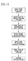
- Members 14A, 14B have a movement sequence schematically illustrated in Figs. 2A to 2E including an initial rest position with resilient pads 16A, 16B spaced apart a distance "m" from each other.
- the movement sequence then includes a coating loading position where resilient pads 16A, 16B are in physical contact and have a degree of compression with each other.
- the degree of compression is determined by comparing the thickness t 1 of pads 16A, 16B in the initial rest position as shown in Fig 2B to thickness t 2 of pads 16A, 16B in Fig. 2B showing the coating loading position.
- the compression of the pads serves to spread the coating onto pads 16A, 16B.
- the compression of the pads in the coating loading step followed by the release of the compression in the intermediate rest position serves to load the coating onto the pads and also to distribute it.
- the movement sequence then includes movement to an intermediate rest position where resilient pads are again spaced apart distance "m” as shown in Fig. 2C, allowing placement of the object to be coated between the pads.
- the movement sequence then includes a coating delivery position where pads 16A, 16B are in physical contact with each other and the object being coated. In the coating delivery position, the pads have a thickness t 3 and a degree of compression with each other and the object being coated as represented in Fig. 2D.
- the degree of compression is determined by comparing the ratio of pad thickness t 3 with thickness t 1 of the initial rest position. In the coating delivery position the coating is transferred from pads 16A, 16B to the object.
- the degree of compression of pads 16A, 16B in the coating loading position (t 2 /t 1 ) is greater than the degree of compression in the coating delivery position (t 3 /t 1 ).
- the degree of compression for coating delivery is less than the degree of compression for coating loading, results show more uniform and precise transfer of the coating to the objects being coated.
- coating supply system 24 includes a reservoir 26 for holding a coating 27 and a transport system 28A, 28B transporting the coating to the pads through holes 46A, 46B.
- Each of the preferred reciprocating members 14A, 14B include drive mechanisms 30A, 30B for reciprocal movement of the pads through the movement sequence.
- apparatus 10 includes an object placement system 34 for placing objects 12 between the pads and then removing the objects.
- Preferred apparatus 10 includes a control system 32 for controlling the coating supply system, the reciprocating member drive system and the object placing system.
- the preferred coating supply system includes having coating transport system 28A, 28B in fluid communication with second sides 44A, 44B of the backing plates 40A, 40B so that a relatively constant supply of coating is maintained at holes 46A, 46B at back sides 56A, 56B of the foam layers 48A, 48B to load the resilient foam layers.
- Control system 32 preferably adjusts coating supply system 28A, 28B so that there is a sufficient amount of coating available for delivery to the object.
- the control system may be mechanical, electromechanical, digital and the like to control the coating delivery, the movement of the reciprocating members and the object placement and removal.
- a suitable material for the porous foam layer is a reticulated polyurethane foam with between about 300 to about 1250 pores per square centimeter.
- a preferred foam is a reticulated polyurethane foam which has been permanently thermally sintered from an as-blown height of between about 5cm to 25cm to a height of about 2.5cm.
- thermal sintering is also described as "felting,” and further described as “firmness” or “firmness ratio” of between 2 and 10.
- Thermal sintering involves compressing the foam from the as-blown thickness to a desired thickness, then heating. When the compression then is released, the foam retains the compressed thickness. This sintering has the effect of increasing the density of the foam by reducing the void volume of the pores in the foam.
- preferred resilient foam pads 16A, 16B have a thickness t 1 between about 0.25cm to about 2.5cm and most preferably between about 0.4cm to about 0.8cm.
- the object being coated is placed substantially centrally between the resilient foam pads so that when the pads are in the coating delivery position, the object is not substantially deflected.
- the positioning of the object is particularly important when the object being coated is pointed, e.g., a hypodermic needle or a catheter mounted over a needle. If a pointed object is deflected during the coating delivery compression, there may be a tendency to cause the point to partially imbed in one pad or the other, potentially damaging the point, reducing the service life of the pad and generating undesirable particles.
- the foam has about 10 to about 100 pores per linear cm with a firmness about 4. This preferred foam will have about 85% to about 90% void volume or open pore space.
- Suitable reticulated polyurethane foams which are available in a range of firmness between 2 and 10, are available as "Foamex SIF felt" from Speciality Polyurethane, 1500 E. Second Street, Eddystone, PA 19013 and from E. E. Murray Co., 707 Umatilla Street, Denver, CO 80204.
- Other foams having similar properties are expected to perform satisfactorily.
- the coating is a lubricant.
- the apparatus of the invention is suitable for application of other coatings including, but not limited to, colorants, pesticides and the like. For these other applications, foams having different composition and properties may be selected and are included in the scope of the invention.
- the degree of compression between resilient pads 16A, 16B in the coating loading position is greater than the degree of compression in the coating delivery position.
- These compression positions have the effect of reducing the void volume or open space within the foam.
- the foam returns to the original uncompressed volume, and at least a portion of the void volume is occupied by the coating charge.
- the foam having a charge of coating is compressed into the coating delivery position, the foam preferably substantially engulfs the object being coated, the coating in the portion of the void volume is displaced and transferred to the object being coated.
- a coating of polydimethyl siloxane is often used as a lubricant on medical devices such as hypodermic needles, scalpels and guidewires made from metal and on medical devices formed from polymeric materials such as catheters and probes.
- the purpose of the lubricant coating is to reduce the sliding friction between the device and tissue or the sliding friction between one component of the device and another.
- silicone lubricant to medical devices there are two conflicting requirements governing the amount applied; there should be some uniform minimum amount applied over the entire surface where the sliding friction is to be reduced; and there should not be excess or visible silicone present on the device.
- the foam used was firmness 4 polyurethane Foamex.
- pads 16A, 16B are each divided into four sections 17A, 17B, the sections being mounted on each reciprocating member to facilitate easy replacement.
- Each section 17A, 17B is about 0.635 cm thick (t 1 ) by 1.27 cm wide by 6.35 cm long giving an uncompressed 16A, 16B volume of 41 cm 3 .
- the void volume, i.e., the pores, in the uncompressed state of the foam is about 88% of 41 cm 3 .
- the foam is under 75% compression, the void volume decreases from 88% to a value of 76%.
- the increase in void volume is 12% of 41 cm 3 or 4.92 cm 3 at least a portion of the void volume then is filled by the preferred coating material, polydimethyl siloxane having a viscosity of 12,500cs.
- polydimethyl siloxane has a viscosity about 12.500cs
- the present invention is suitable for application of polydimethyl siloxanes or other coatings with Brookfield viscosities at 25°C. between about 10cs to about 1,000,000cs.
- the 24 hour trial run of the apparatus of the present invention was conducted to apply 12,500cs polydimethyl siloxane for lubrication to the 14g peripheral venous catheters mounted over needles. Samples of the coated catheters were taken at regular intervals and the amount of silicone lubricant present on their surface was determined by extraction.
- the reciprocating members are mounted so that the pads are vertical with the motion toward and away from each other being horizontal.
- top surfaces 19A, 19B of the resilient pads are sealed so that when the pads are in the compressed state the coating cannot pass through the top surface of the pad and pool on surfaces 19A, 19B of the pads.
- the top surface may be sealed by adhesive, fusing by heat, ultrasound and the like.
- top surfaces 19A, 19B are fused by pressing against a smooth surfaced heated above the melting point of the polyurethane foam forming a skin.
- control system 32 is preferably adjusted so that the amount of coating material delivered to the foam pads is only a slight excess to the desired amount being applied to the catheters. The slight excess cannot pool on the top surface because of the sealed surfaces 19A, 19B and migrates to the bottom of the pads where it may be collected without effecting the amount present on the catheters. The slight excess delivery to the pads ensures that the distribution into the pads during the coating loading cycle is sufficient to provide substantially uniform coverage of the object being coated.
- the coating apparatus of the present invention may be compactly built to fit on assembly machines into space currently used for solvent based coating apparatus.
- the apparatus and method for its use demonstrate a capability to produce product having similar quality and performance properties to standard commercial product produced with solvent based coating.
- the apparatus of the present invention is also compatible with the assembly rate requirements and efficiency of current assembly machines using solvent based coating systems.
- the present invention provides a simple and reliable coating station for medical device assembly machines allowing manufacturers to eliminate the use of solvent based coating systems in many applications.
Landscapes
- Health & Medical Sciences (AREA)
- Animal Behavior & Ethology (AREA)
- Veterinary Medicine (AREA)
- Anesthesiology (AREA)
- Biomedical Technology (AREA)
- Heart & Thoracic Surgery (AREA)
- Hematology (AREA)
- Engineering & Computer Science (AREA)
- General Health & Medical Sciences (AREA)
- Life Sciences & Earth Sciences (AREA)
- Public Health (AREA)
- Vascular Medicine (AREA)
- Coating Apparatus (AREA)
- Application Of Or Painting With Fluid Materials (AREA)
- Materials For Medical Uses (AREA)
- Springs (AREA)
Claims (10)
- Vorrichtung (10) zum Aufbringen eines Überzugs auf einen Gegenstand (12), umfassend ein Überzugszufuhrsystem (24) zum Liefern eines Überzugs auf die elastischen Puffer (16A, 16B) und Glieder (14A, 14B) mit sequentieller Bewegung,
dadurch gekennzeichnet, daß
die Glieder sich hin und her bewegende Glieder (14A, 14B) sind, jedes einen porösen elastischen Puffer (16A, 16B) umfassend, wobei die Glieder montiert sind für Bewegung zu und weg voneinander, und
die sequentiellen Bewegungspositionen umfassen eine Anfangsruheposition, wo die elastischen Puffer (16A, 16B) mit Abstand voneinander angeordnet sind, eine Überzugsbeladungsposition, wo die elastischen Puffer (16A, 16B) mit Abstand voneinander angeordnet sind, eine Überzugsbeladungsposition, wo die elastischen Puffer (16A, 16B) in physischem Kontakt miteinander sind und einen Kompressionsgrad miteinander haben, wodurch der Überzug in die Puffer (16A, 16B) geladen wird, eine Zwischenruheposition, wo die elastischen Puffer (16A, 16B) mit Abstand voneinander angeordnet sind, so daß ein zu überziehender Gegenstand (12) zwischen den elastischen Puffern plazierbar (16A, 16B) ist, eine Überzugsabgabeposition, wo die elastischen Puffer (16A, 16B) in physischem Kontakt miteinander und mit dem zu überziehenden Gegenstand (12) sind, wobei die Puffer (16A, 16B) einen Kompressionsgrad miteinander und dem zu überziehenden Gegenstand (12) haben, um den Überzug auf den Gegenstand (12) aufzubringen. - Vorrichtung nach Anspruch 1, wobei der Kompressionsgrad in der Überzugsbeladungsposition größer als der Kompressionsgrad in der Überzugsabgabeposition ist.
- Vorrichtung nach Anspruch 1, wobei das Überzugszufuhrsystem (24) ein Reservoir (26) und ein Transportsystem (28A, 28B) zum Liefern des Überzugs zu den elastischen Puffern (16A, 16B) umfaßt.
- Vorrichtung nach Anspruch 1, wobei jedes der sich hin und her bewegenden Glieder (14A, 14B) ferner einen Antriebsmechanismus (30A, 30B) und eine Trägerplatte (40A, 40B) zum Montieren der elastischen Puffer (16A, 16B) einschließt.
- Vorrichtung nach Anspruch 4, wobei die Trägerplatten (40A, 40B) eine erste Seite (42A, 42B) und eine zweite Seite (44A, 44B) haben und ferner eine Vielheit von Öffnungen dadurch einschließen, wobei die erste Seite (42A, 42B) die elastischen Puffer (16A, 16B) darauf montiert hat, und die Öffnungen sind in Fluidumverbindung mit der zweiten Seite (44A, 44B) zu dem Überzugszufuhrsystem (24) zum Liefern des Überzugs zu den elastischen Puffern (16A, 16B).
- Vorrichtung nach Anspruch 1, wobei die elastischen Puffer (16A, 16B) Schaum sind und eine versiegelte Oberseitenoberfläche haben, wobei die versiegelte Oberseitenoberfläche im wesentlichen dazu dient, den Überzug von sich Zusammenschließen auf der Oberseitenoberfläche des Puffers (16A, 16B) abzuhalten, wenn die Puffer (16A, 16B) in der Überzugsbeladungsposition komprimiert werden.
- Vorrichtung nach Anspruch 1, wobei der Überzug ein Gleitmittel ist, umfassend Polydimethylsiloxan mit einer Brookfieldviskosität zwischen etwa 100 Centistokes bis etwa 1 000 000 Centistokes.
- Verfahren zum Aufbringen eines Überzugs auf einen Gegenstand (12), umfassend:Plazieren eines zu überziehenden Gegenstandes (12) zwischen zwei sich hin und her bewegenden Gliedern (14A, 14B), wobei jedes einen porösen elastischen Puffer (16A, 16B) umfaßt, montiert für Bewegung zu und weg voneinander, wobei das Plazieren auftritt, wenn die Puffer (16A, 16B) in einer Position sind, die die Puffer (16A, 16B) mit Abstand voneinander angeordnet hat und mit einer Beladung eines auf den Gegenstand (12) aufzubringenden Überzugs, undBewegen der Puffer (16A, 16B) von der Position, die die Puffer (16A, 16B) mit Abstand voneinander angeordnet hat, zu einer Position, die die Puffer (16A, 16B) in physischem Kontakt miteinander und dem zu überziehenden Gegenstand (12) hat, so daß die Puffer (16A, 16B) einen Kompressionsgrad miteinander und dem zu überziehenden Gegenstand (12) haben, wodurch der Überzug auf den Gegenstand (12) aufgebracht wird.
- Verfahren nach Anspruch 8, wobei der Gegenstand (12) ein Zylinder ist, der ein Verhältnis von Länge zu Durchmesser größer als drei zu eins hat, und die. Plazierungsstufe umfaßt Plazieren des Gegenstandes (12) zwischen den Puffern (16A, 16B), wenn die Puffer (16A, 16B) mit Abstand voneinander angeordnet sind, so daß, wenn die Puffer (16A, 16B) zu der Position bewegt werden, die die Puffer (16A, 16B) in physischem Kontakt miteinander und dem Gegenstand (12) hat, der Kompressionsgrad zwischen den Puffern (16A, 16B) und dem Gegenstand (12) ähnlich von jedem Puffer (16A, 16B) ist, so daß der Gegenstand (12) nicht wesentlich abgelenkt wird.
- Verfahren nach Anspruch 9, wobei die sich hin und her bewegenden Glieder (14A, 14B) ferner ein Überzugszufuhrsystem (24) einschließen, und das Beladen des Überzugs der elastischen Puffer (16A, 16B) umfaßt ferner Bewegen der Puffer (16A, 16B) von einer Position, die die Puffer (16A, 16B) mit Abstand voneinander angeordnet hat, zu einer Überzugsbeladungsposition, die die Puffer (16A, 16B) in physischem Kontakt miteinander und mit einen Kompressionsgrad miteinander hat, wodurch der Überzug in die Puffer (16A, 16B) geladen wird, wobei die Überzugsbeladungsstufe vor der Gegenstand (12) Plazierungsstufe auftritt.
Applications Claiming Priority (2)
| Application Number | Priority Date | Filing Date | Title |
|---|---|---|---|
| US509395 | 1990-04-16 | ||
| US50939595A | 1995-07-31 | 1995-07-31 |
Publications (2)
| Publication Number | Publication Date |
|---|---|
| EP0756901A1 EP0756901A1 (de) | 1997-02-05 |
| EP0756901B1 true EP0756901B1 (de) | 2002-06-12 |
Family
ID=24026490
Family Applications (1)
| Application Number | Title | Priority Date | Filing Date |
|---|---|---|---|
| EP96305278A Expired - Lifetime EP0756901B1 (de) | 1995-07-31 | 1996-07-18 | Einrichtung und Verfahren für Beschichtung von Gegenständen unter Verwendung einer porösen elastischen Matrix |
Country Status (7)
| Country | Link |
|---|---|
| US (2) | US5863614A (de) |
| EP (1) | EP0756901B1 (de) |
| JP (1) | JP2803813B2 (de) |
| AU (1) | AU701687B2 (de) |
| CA (1) | CA2180907A1 (de) |
| DE (1) | DE69621709T2 (de) |
| ES (1) | ES2178694T3 (de) |
Families Citing this family (18)
| Publication number | Priority date | Publication date | Assignee | Title |
|---|---|---|---|---|
| DE19744367C1 (de) * | 1997-10-08 | 1998-11-05 | Schott Glas | Verfahren und Vorrichtung zur Beschichtung medizinischer Kanülen |
| DE19753766A1 (de) | 1997-12-04 | 1999-06-17 | Schott Glas | Länglicher Kunststoff-Hohlkörper und Verfahren zu seiner Herstellung |
| US7479128B1 (en) * | 2000-01-04 | 2009-01-20 | Boston Scientific Scimed, Inc. | Protective coatings for medical devices |
| DE20011006U1 (de) | 2000-06-28 | 2001-08-30 | Ze Be S GmbH Wolfen Zentrum für Beschichtung und Spezialmeßtechnik, 06766 Wolfen | Vorrichtung zur Beschichtung und Benetzung von Warenbahnen |
| DE10113022B4 (de) * | 2001-03-17 | 2013-05-29 | Volkswagen Ag | Vorrichtung zum Lackieren einer Fläche eines Bauteils |
| US20040261698A1 (en) * | 2001-09-27 | 2004-12-30 | Roorda Wouter E. | Stent coating apparatus |
| DE10226281A1 (de) * | 2002-06-13 | 2003-12-24 | Emitec Emissionstechnologie | Verfahren und Vorrichtung zum Beleimen einer Wabenstruktur |
| WO2006127533A1 (en) * | 2005-05-20 | 2006-11-30 | Charlie Hubbs | Silicone-impregnated foam product and method for producing same |
| ES2543735T3 (es) * | 2007-10-22 | 2015-08-21 | Becton Dickinson And Company | Artículos médicos revestidos con organopolisiloxano que contienen una disolución de proteína y un tensioactivo no iónico |
| JP4630960B2 (ja) * | 2008-08-07 | 2011-02-09 | 株式会社アサカ精機 | 潤滑剤連続塗布装置 |
| JP5498203B2 (ja) * | 2010-03-02 | 2014-05-21 | 矢崎総業株式会社 | 電線の着色方法 |
| PT2552788E (pt) * | 2010-03-26 | 2015-11-17 | Philip Morris Products Sa | Sistema de distribuição de líquido para uso na formação dum produto de tabaco em forma de bolsa |
| DK201001011A (da) * | 2010-11-08 | 2012-05-09 | Hove As | Fremgangsmåde og anlæg til påføring af et overfladelag på et emne |
| CN104549872B (zh) * | 2014-12-31 | 2017-01-11 | 迈得医疗工业设备股份有限公司 | 一种输液器导管外涂胶装置 |
| CN104437958B (zh) * | 2014-12-31 | 2017-01-11 | 迈得医疗工业设备股份有限公司 | 一种用于输液器导管外涂胶的涂胶爪 |
| CN104646229B (zh) * | 2014-12-31 | 2016-08-17 | 迈得医疗工业设备股份有限公司 | 一种导管涂胶装置的涂胶爪 |
| CN104525428B (zh) * | 2014-12-31 | 2017-01-11 | 迈得医疗工业设备股份有限公司 | 一种输液器导管外涂胶结构 |
| ES2797298T3 (es) | 2016-02-10 | 2020-12-01 | Becton Dickinson France | Procedimiento para evaluar la estabilidad de una formulación a base de proteína |
Family Cites Families (14)
| Publication number | Priority date | Publication date | Assignee | Title |
|---|---|---|---|---|
| US2716076A (en) * | 1952-10-08 | 1955-08-23 | Luminous Processes Inc | Method and apparatus of radium coating |
| US2926628A (en) * | 1956-09-07 | 1960-03-01 | Robert S Black | Roll type glue spreaders, surface coaters, and the like |
| JPS58906B2 (ja) * | 1979-04-09 | 1983-01-08 | 麒麟麦酒株式会社 | 壜等の塗布装置 |
| DE3045950C2 (de) * | 1980-12-05 | 1984-03-01 | Sortimat Creuz & Co Gmbh, 7057 Winnenden | Verfahren und Vorrichtung zum Silikonisieren reibend beanspruchter Flächen von Spritzenzylindern |
| US4604300A (en) * | 1985-04-03 | 1986-08-05 | Essex Group, Inc. | Method for applying high solids enamels to magnet wire |
| JPH01209608A (ja) * | 1988-02-17 | 1989-08-23 | Hitachi Cable Ltd | エナメル線用アプリケータおよびエナメル線装置 |
| US5085169A (en) * | 1988-11-28 | 1992-02-04 | Sunstar Engineering Inc. | Method of and apparatus for applying a paint |
| US4962721A (en) * | 1988-12-08 | 1990-10-16 | Sewell Plastics Inc. | Apparatus for coating a container with a liquid |
| US4958587A (en) * | 1989-06-29 | 1990-09-25 | International Marketing, Inc. | Apparatus for exteriorly painting and interiorly coating tires |
| US5207293A (en) * | 1989-09-13 | 1993-05-04 | Becton, Dickinson And Company | Method and apparatus for lubricating stoppers for syringe barrels |
| DE4105364C1 (de) * | 1991-02-21 | 1992-05-27 | Zibulla & Sohn Gmbh Raziol Schmierungstechnik, 5860 Iserlohn, De | |
| AT404088B (de) * | 1992-01-31 | 1998-08-25 | Haas Franz Waffelmasch | Verfahren und vorrichtung zum konditionieren von verrottbaren, vorzugsweise essbaren dünnwandigen formkörpern, welche in geschlossenen formen aus backmassen gebacken wurden, die auf der basis von cerealienmehlen und/oder stärke hergestellt sind |
| JP3241113B2 (ja) * | 1992-07-20 | 2001-12-25 | 日本クラウンコルク株式会社 | 金属製キャップの防錆塗料塗布装置 |
| CA2180897A1 (en) * | 1995-07-31 | 1997-02-01 | Victor A. Williamitis | Apparatus and method for coating of objects using a porous resilient matrix |
-
1996
- 1996-07-10 CA CA002180907A patent/CA2180907A1/en not_active Abandoned
- 1996-07-18 EP EP96305278A patent/EP0756901B1/de not_active Expired - Lifetime
- 1996-07-18 DE DE69621709T patent/DE69621709T2/de not_active Expired - Lifetime
- 1996-07-18 ES ES96305278T patent/ES2178694T3/es not_active Expired - Lifetime
- 1996-07-26 AU AU60756/96A patent/AU701687B2/en not_active Ceased
- 1996-07-31 JP JP8202277A patent/JP2803813B2/ja not_active Expired - Lifetime
-
1997
- 1997-05-28 US US08/864,574 patent/US5863614A/en not_active Expired - Lifetime
- 1997-05-28 US US08/864,610 patent/US5853481A/en not_active Expired - Fee Related
Also Published As
| Publication number | Publication date |
|---|---|
| DE69621709T2 (de) | 2003-01-02 |
| AU6075696A (en) | 1997-02-06 |
| JPH09103733A (ja) | 1997-04-22 |
| AU701687B2 (en) | 1999-02-04 |
| EP0756901A1 (de) | 1997-02-05 |
| US5863614A (en) | 1999-01-26 |
| US5853481A (en) | 1998-12-29 |
| DE69621709D1 (de) | 2002-07-18 |
| CA2180907A1 (en) | 1997-02-01 |
| JP2803813B2 (ja) | 1998-09-24 |
| ES2178694T3 (es) | 2003-01-01 |
Similar Documents
| Publication | Publication Date | Title |
|---|---|---|
| AU701687B2 (en) | Apparatus and method for coating of objects using a porous resilient matrix | |
| US5773081A (en) | Method for coating of objects using a rotating resilient matrix | |
| US5338312A (en) | Article having multi-layered lubricant and method therefor | |
| US6296893B2 (en) | Pharmaceutical packing device comprising a hollow plastic body having an improved internal lubricant layer and method of making same | |
| EP2676741B1 (de) | Verbesserter gegenstand mit geschmierter oberfläche und verfahren | |
| EP0005035B1 (de) | Verfahren zur Herstellung eines Rohrprodukts durch elektrostatisches Spinnen | |
| US6254921B1 (en) | Coating process and apparatus | |
| US5483719A (en) | Hair brush with porous polytetrafluoroethylene body | |
| JP2021126657A (ja) | 液体含浸表面を有する装置 | |
| US20090010985A1 (en) | Article with Lubricated Surface and Method | |
| EP0698463A2 (de) | Schmierstoff zur Verwendung auf ein Kathetherende | |
| US6117480A (en) | Method and means for coating medical cannulas | |
| CA1271160A (en) | Ionizing plasma lubricant method | |
| WO2017127534A1 (en) | Partially lubricated syringe barrels, plungers, and seal members and related methods | |
| US8852669B2 (en) | Coating method and coating device for medical implants | |
| JPS631061B2 (de) | ||
| KR20220090396A (ko) | 도포 장치 및 도포 방법 | |
| JP7604663B2 (ja) | 薄膜潤滑剤を有する薬剤注射ストッパ | |
| JP4670113B2 (ja) | 直動軸受 | |
| JP6600308B2 (ja) | 流体をサブストレートの幅全体に亘って塗り広げる装置及びその使用方法 | |
| JP2003205261A (ja) | 円筒状部分を有する物体の外周面に潤滑油を均一塗布する装置及び方法 | |
| JP7391554B2 (ja) | 塗布装置および塗布方法 | |
| ES2166818T3 (es) | Dispositivo para conferir propiedades anti-friccion a un alambre metalico. |
Legal Events
| Date | Code | Title | Description |
|---|---|---|---|
| PUAI | Public reference made under article 153(3) epc to a published international application that has entered the european phase |
Free format text: ORIGINAL CODE: 0009012 |
|
| AK | Designated contracting states |
Kind code of ref document: A1 Designated state(s): DE ES FR GB |
|
| 17P | Request for examination filed |
Effective date: 19970731 |
|
| 17Q | First examination report despatched |
Effective date: 19990415 |
|
| GRAG | Despatch of communication of intention to grant |
Free format text: ORIGINAL CODE: EPIDOS AGRA |
|
| GRAG | Despatch of communication of intention to grant |
Free format text: ORIGINAL CODE: EPIDOS AGRA |
|
| GRAH | Despatch of communication of intention to grant a patent |
Free format text: ORIGINAL CODE: EPIDOS IGRA |
|
| GRAH | Despatch of communication of intention to grant a patent |
Free format text: ORIGINAL CODE: EPIDOS IGRA |
|
| GRAA | (expected) grant |
Free format text: ORIGINAL CODE: 0009210 |
|
| AK | Designated contracting states |
Kind code of ref document: B1 Designated state(s): DE ES FR GB |
|
| REG | Reference to a national code |
Ref country code: GB Ref legal event code: FG4D |
|
| REF | Corresponds to: |
Ref document number: 69621709 Country of ref document: DE Date of ref document: 20020718 |
|
| ET | Fr: translation filed | ||
| REG | Reference to a national code |
Ref country code: ES Ref legal event code: FG2A Ref document number: 2178694 Country of ref document: ES Kind code of ref document: T3 |
|
| PLBE | No opposition filed within time limit |
Free format text: ORIGINAL CODE: 0009261 |
|
| STAA | Information on the status of an ep patent application or granted ep patent |
Free format text: STATUS: NO OPPOSITION FILED WITHIN TIME LIMIT |
|
| 26N | No opposition filed |
Effective date: 20030313 |
|
| REG | Reference to a national code |
Ref country code: FR Ref legal event code: PLFP Year of fee payment: 20 |
|
| PGFP | Annual fee paid to national office [announced via postgrant information from national office to epo] |
Ref country code: GB Payment date: 20150727 Year of fee payment: 20 Ref country code: ES Payment date: 20150727 Year of fee payment: 20 Ref country code: DE Payment date: 20150729 Year of fee payment: 20 |
|
| PGFP | Annual fee paid to national office [announced via postgrant information from national office to epo] |
Ref country code: FR Payment date: 20150717 Year of fee payment: 20 |
|
| REG | Reference to a national code |
Ref country code: DE Ref legal event code: R071 Ref document number: 69621709 Country of ref document: DE |
|
| REG | Reference to a national code |
Ref country code: GB Ref legal event code: PE20 Expiry date: 20160717 |
|
| REG | Reference to a national code |
Ref country code: ES Ref legal event code: FD2A Effective date: 20161026 |
|
| PG25 | Lapsed in a contracting state [announced via postgrant information from national office to epo] |
Ref country code: GB Free format text: LAPSE BECAUSE OF EXPIRATION OF PROTECTION Effective date: 20160717 |
|
| PG25 | Lapsed in a contracting state [announced via postgrant information from national office to epo] |
Ref country code: ES Free format text: LAPSE BECAUSE OF EXPIRATION OF PROTECTION Effective date: 20160719 |